
Related Manuals for Nordson TCB


Summary of Contents for Nordson TCB
- Page 1 Installation, Operation and Maintenance Manual Total Control Board 7146919-05 (GB) 0610 Freedom from patent restrictions must not be assumed.
- Page 2 Installation, Operation and Maintenance Manual 7146919-05 (GB) 0610 Freedom from patent restrictions must not be assumed.
- Page 3 Installation, Operation and Maintenance Manual IMPORTANT PLEASE READ THIS MANUAL CAREFULLY BEFORE INSTALLATION THIS MANUAL SHOULD BE READ IN CONJUNCTION WITH THE RESPECTIVE PRODUCT MANUAL AND CIRCUIT DRAWINGS SUPPLIED WITH THE AFTERFILTER EXPLANATION OF SYMBOLS USED Refers to special information regarding the most efficient use. Refers to special information directed towards preventing damage.
-
Page 4: Table Of Contents
Installation, Operation and Maintenance Manual TABLE OF CONTENTS Introduction Delivery and MOUNTING INSTRUCTIONS 2.1. Enclosure location 2.2. Pneumatic installation Electrical installation 3.1. Main switch IP65 3.2. Motor connection 3.3. Supply voltage: terminals 1 and 2 3.4. RS-485 Bus: terminal 3–5 3.5. Motor protection: terminals 25, 28 3.6. - Page 5 7.23. M05 Total Operating Hours ALARM MESSAGES and fault location Maintenance Options and features Specifications Spare Parts EC DECLARATION OF CONFORMITY TABLE OF FIGURES 1: TCB ............................7 IGURE FRONT PANEL 2: T PCB ......................10 IGURE ERMINAL VIEW OF MODULE 3: W PCB ( ) .....................
-
Page 6: Introduction
Due to the varied nature of site installations this cannot be provided by Nordson but instead is the responsibility of the customer. For installation in hazardous areas, all work must be carried out with the electrical supply isolated or only when the potentially explosive atmosphere is not present. -
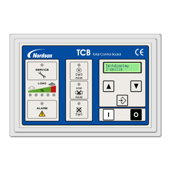
Page 7: F Igure 1: Tcb Front Panel
LED ‘Off-line Cleaning’ ENTER-button Push button fan OFF 10. LED ‘Service’ Scroll UP button LED ‘FAN ON / PULSE’ 11. LED bar-graph indication Scroll DOWN button LED ‘Cleaning stopped’ of differential pressure 12. ‘Alarm’ LED Figure 1: TCB front panel... -
Page 8: Delivery And Mounting Instructions
Installation, Operation and Maintenance Manual 2. DELIVERY AND MOUNTING INSTRUCTIONS The TCB is normally delivered pre-mounted and pre-wired with the Afterfilter. In case the TCB is shipped loose with the unit, follow the next steps to ensure a faultless functioning of the control box. -
Page 9: Electrical Installation
For pre-wired units the motor connections will be made directly to the contactors of the fan according the wiring diagram delivered inside the TCB enclosure. For controllers shipped loose connections should be made to the DIN rail terminals according to the... -
Page 10: Supply Voltage: Terminals 1 And
3.3. Supply voltage: terminals 1 and 2 The supply voltage for the power box can be either 200V AC, 230V, 380V, 400V (standard TCB), 440V or 480V, 50 or 60 Hz. A transformer with 63VA or 110VA output will be used. The electronic modules will be supplied with pre-wired 24V AC on terminals 1 and 2. -
Page 11: Optional Isolation Amplifier For Thermistor Protection And/Or Bursting Disc: Terminals
9 a potential free contact (NC) is available as output signal. This output signal can then be used for example to initiate an alarm in the TCB by connecting it to terminals 26 and 28. The terminals for the thermistor will be included as standard on the TCB board, but the Thermistor module itself is an option. -
Page 12: Outputs For Remote Control Lamps: Terminals
Valve outputs: terminals V1–V16 – Multiple module systems Where the TCB is used to operate more than 32 valves a serial linked system is used. The master TCB will contain an I/O module for connection of motor contactors, alarms, input and output signals. Valves will be connected using 3 or more slave modules connected to the system using the RS-485 bus connection. -
Page 13: Programmable Inputs
Installation, Operation and Maintenance Manual 3.16. Programmable inputs Two additional alarms / inputs can be connected to the terminals 26, 27 and 28. The function of these alarm inputs can be selected by the software (see chapter 7.11). Input I1 = terminals 26-28, Input I2 = terminals 27-28. Terminals bridged = no alarm / input, opening connection = alarm / input active. - Page 14 Installation, Operation and Maintenance Manual Terminal Item Description Remarks Serial link connection between display and I/O 3,4,5 RS 485 Bus connection Connection modules Max. contact load of Relay output signal for Thermistor circuit or bursting Outputs 8, 9 Thermistor / bursting disc relays: 5 A - 230 VAC disc Reed-contact.
-
Page 15: Pre-Start-Up Checklist
5. OPERATION 5.1. Single Fan Afterfilter Systems The TCB control board provides the output signals to the diaphragm valves mounted on the Afterfilter and also controls the fan motor start-up procedure (and can controls other auxiliary equipment if fitted –... -
Page 16: Status Led's
5.3. Status LED’s The status LEDs on the front display panel of the TCB have the following meanings: SERVICE LED - When during normal operation the service LED lights up, the unit needs to be checked by a Nordson representative. -
Page 17: Using The Menu System
ENTER the menu system or execute a function. 6.1. Display mode During normal operation the LCD display on the TCB indicates the current differential pressure over the filter elements. In the display mode it is possible to view all settings without the possibility to change them. - Page 18 Installation, Operation and Maintenance Manual You can now scroll through all parameters in the setting mode. To change a parameter push the ENTER button and the value can be changed. The new value needs to be confirmed by pushing the ENTER button again for 2 seconds otherwise the changed value will not be saved, but instead the message “Program cancelled”...
-
Page 19: Parameter/Memory Fields Description
Installation, Operation and Maintenance Manual Shows the valve that is being pulsed. ACTIVE PULSE 2.20 XX: Number of module No setting possible P46 VALVE XX YY YY: Number of valve TEST CONTROLLER After pressing ENTER all LED’s on the 2.21 control panel light up for 10 sec TOTAL OPERAT H Shows the total number of operating... -
Page 20: P06 Off Line Cleaning Cycles
Installation, Operation and Maintenance Manual 7.6. P06 Off Line cleaning Cycles OFF_LINE_CLEAN_C PO6_____XX_CYCLES Once the fan set is switched off, Off Line Cleaning is initiated and completes the number of cycles selected here. You can choose anything between 0 and 15 cycles. If the setting is “0”, Off Line Cleaning is switched off. -
Page 21: P17 Function Of Input I1 (Terminals 26-28)
Input functions 2 – 6 and 7 & 8 are not available when the TCB is used to operate several fans in ECB mode. -
Page 22: P19 Function Of Output Relay O1 (Relay Contact Cleaning On / Terminals 10-11)
ENTER button or remotely by a signal on Input I1 or I2. These output functions are not available when the TCB is used to operate several fans in ECB mode. (The relays are then used to power the fan contactors for fans 4 and the working area lighting circuit). -
Page 23: P22 Delta P Cleaning Mode
Installation, Operation and Maintenance Manual 7.15. P22 Delta P Cleaning mode Delta P Cleaning DP_CLEAN_MODE___ Cleaning is not influenced by the differential pressure mode P22_0_CONT_CLEAN_ measurement, but instead the valves will pulse continuously. Differential pressure measurement and monitoring are activated. DP_CLEAN_MODE___ Cleaning is carried out based on the differential pressure P22_1_STOP_&_GO... -
Page 24: P41 Set Time And Date
7.19. P44 Program Version PROGRAM_VERSION_ P44_VXX.XX.XX/X This parameter field shows the version of the software. The update and/or uploading of new software can only be done by a Nordson representative. 7.20. P46 Active Pulse Display ACTIVE_PULSE____ P46_VALVE__XX_YY This parameter field shows the number of the valve that is last activated. -
Page 25: P50 Back To Factory Settings
Installation, Operation and Maintenance Manual 7.22. P50 Back To Factory Settings FACTORY_SETTINGS P50__________YES FACTORY_SETTINGS P50______CONFIRM With this parameter the system will reset all the parameters as described in the next table to default factory settings. Code Description Display line Factory settings DP_MIN__________ Delta P Min 40 daPa... -
Page 26: Alarm Messages And Fault Location
Installation, Operation and Maintenance Manual 8. ALARM MESSAGES AND FAULT LOCATION The TCB control box will display an alarm message when it detects a possibly dangerous situation for the installation. When this happens first of all it is necessary to investigate the cause of the alarm. - Page 27 TCB) the unit is switched on; in triangle the fan Incorrect wiring to fan Check wiring from TCB to fan stops. No cleaning pulses but the LED ‘Pulse Check supply voltage (a low voltage will not Low supply voltage.
- Page 28 Installation, Operation and Maintenance Manual Symptom Possible cause Action Check compressor capacity. Check pulse Weak pulses. Air supply inadequate. interval – air pressure in manifold should return to required value before next pulse. Check supply voltage and connections to Supply voltage too low. Control box.
-
Page 29: Maintenance
Installation, Operation and Maintenance Manual 9. MAINTENANCE In general the TCB control box does not require any maintenance. There are some items however that need to be checked on a regular basis: In-line Micrafilters in the air lines: when these are very dirty, there will be a pressure drop over them, making the differential pressure measurement over the elements unreliable. -
Page 30: Specifications
I/O Module T 2,0 A, 250 VAC, 5 x 20 mm Display – PTC Device. Dimensions Display PCB. 258 x 175 x 65 mm I/O Module PCB 220 x 80 mm 12. SPARE PARTS ITEM Nordson Part No. TCB,DISPLAY,CONTROLLER,GEN5 A/F 7034116 TCB, I/O MODULE,GEN5 A/F 7034117... -
Page 31: Ec Declaration Of Conformity
We hereby declare that the product specified conforms to the directives and standards described above and that it has been provided with a CE label. Provided the product is installed and operated in line with the Nordson manuals, its operation is safe. Kai Flockenhaus Manager Procurement &...
Need help?
Do you have a question about the TCB and is the answer not in the manual?
Questions and answers