Nordson Tribomatic II Customer Product Manual
Three-gauge control unit
Hide thumbs
Also See for Tribomatic II:
- Customer product manual (55 pages) ,
- Instruction sheet (16 pages) ,
- Customer product manual (36 pages)

Subscribe to Our Youtube Channel
Related Manuals for Nordson Tribomatic II


Summary of Contents for Nordson Tribomatic II
- Page 1 Tribomatic Three-Gauge Control Unit Customer Product Manual Part 106812B Issued 5/03 NORDSON CORPORATION AMHERST, OHIO USA...
-
Page 2: Table Of Contents
555 Jackson Street Amherst, OH 44001 Notice This is a Nordson Corporation publication which is protected by copyright. Original copyright date 1995. No part of this document may be photocopied, reproduced, or translated to another language without the prior written consent of Nordson Corporation. The information contained in this publication is subject to change without notice. -
Page 3: Safety
Regulations and Approvals Make sure all equipment is rated and approved for the environment in which it is used. Any approvals obtained for Nordson equipment will be voided if instructions for installation, operation, and service are not followed. All phases of equipment installation must comply with all federal, state, and local codes. -
Page 4: Personal Safety
Clean, maintain, test, and repair equipment according to the instructions in your equipment documentation. Use only replacement parts that are designed for use with original equipment. Contact your Nordson representative for parts information and advice. Part 106812B E 2003 Nordson Corporation... -
Page 5: Grounding
Disconnect and lock out electrical power. Close pneumatic shutoff valves and relieve pressures. Identify the reason for the malfunction and correct it before restarting the equipment. Disposal Dispose of equipment and materials used in operation and servicing according to local codes. Part 106812B E 2003 Nordson Corporation... -
Page 6: Safety Labels
1. To be installed in accordance with all local codes and ordinances, all pertinent statutes and regulations, and the safety provisions of the Nordson manual. 2. Ground all equipment and other metal objects within 10 ft (3 m) of spray area. Keep spray area clean. - Page 7 PART NO. INPUT: 100-120/200-240 VAC SERIAL NO. 50/60 HZ, 1 0.2 AMP NORDSON SVERIGE AB ICAB DIV. MADE IN SWEDEN 1401184A Figure 1-1 Safety Labels Part 106812B E 2003 Nordson Corporation...
- Page 8 Safety Part 106812B E 2003 Nordson Corporation...
-
Page 9: Description
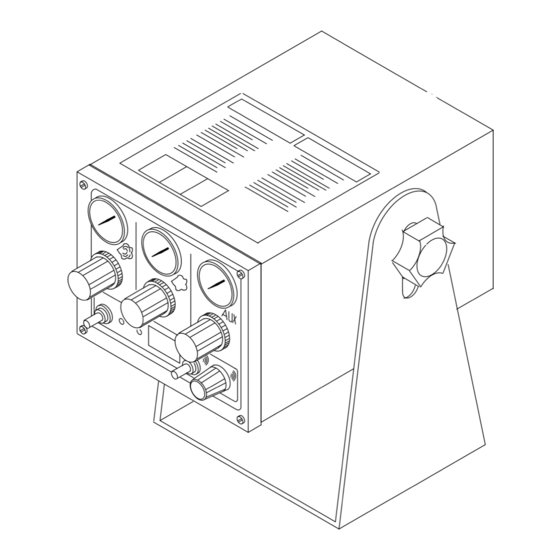
Description Introduction The Nordson Tribomatic II three-gauge control unit provides pneumatic and electrical controls for a Tribomatic II manual powder spray gun. The control unit consists of a control module installed in a cabinet. 1401185A Figure 2-1 Tribomatic Control Unit 1. -
Page 10: Front Panel Controls
Description Front Panel Controls See Figure 2-2 and Refer to Table 2-1. 1401187A Figure 2-2 Front Panel Controls Part 106812B E 2003 Nordson Corporation... - Page 11 Air flows when unit is externally triggered (SW5 is set to external trigger) or when unit is powered up (SW5 set to standalone). Pull the regulator knob out to change the air pressure, push the knob in to lock the setting. Part 106812B E 2003 Nordson Corporation...
-
Page 12: Rear Panel Connections
Power cord Input power connection. Three-lead unterminated cord. Customer must furnish three-prong plug. 6-pin receptacle Connects manual gun cable to control unit. In addition to trigger circuit, grounds gun and operator through module and cabinet. Part 106812B E 2003 Nordson Corporation... -
Page 13: Specifications
(100 psi). Also, use a filter system with pre-filters and coalescent filters capable of removing oil, water, and dirt in the submicron range. Symbols Symbols used on this equipment are described in Figure 2-4. GROUND FLOW-RATE AIR DIFFUSER AIR ALARM 1401186A Figure 2-4 Symbols Part 106812B E 2003 Nordson Corporation... -
Page 14: Installation
(4) out of the cabinet (1). Disconnect the ground wire (5) from the module, if necessary. 1401189A Figure 3-1 Removing the Control Module from the Cabinet 1. Cabinet 3. Captive screws 5. Ground wire 2. Circuit board 4. Control module Part 106812B E 2003 Nordson Corporation... - Page 15 When set to DELAY, flow-rate air is turned on before diffuser air. This switch is not present on revision A or B circuit boards. DIRECT Set to DIRECT for all guns except Tribomatic I automatic guns. 1401191A Figure 3-2 Circuit Board Setup Part 106812B E 2003 Nordson Corporation...
-
Page 16: Mechanical Installation
Thread the cable nut onto the receptacle and tighten it securely. Cabinet Ground Connect the ground strap furnished with the control unit to the ground stud (6) on the rear of the cabinet. Secure the clamp to an earth ground. Part 106812B E 2003 Nordson Corporation... -
Page 17: Pneumatic Connections
NOTE: Install a manually operated, locking shut-off valve in the supply line in front of the control unit. Part 106812B E 2003 Nordson Corporation... -
Page 18: Operation
If the pressure is too high the spray spray gun. gun parts may wear faster. Decreasing will increase the density of the powder-and provide better coverage. If the pressure is too low the powder may clog the spray gun passages. Part 106812B E 2003 Nordson Corporation... -
Page 19: Startup
A output on the chart furnished at the end of this section. Use these values to set air pressures the next time the same powder is used and to monitor the powder charge. Part 106812B E 2003 Nordson Corporation... -
Page 20: Shutdown
Ungrounded equipment and parts may accumulate a charge which could arc and cause a fire or explosion. Clean powder and dust off the control unit cabinet with a clean cloth or brush. Part 106812B E 2003 Nordson Corporation... -
Page 21: Control Unit Settings
This chart can be copied and posted next to the control unit. Significant deviations from the recorded A output could indicate problems with the powder, air, or gun. Air Pressures Powder Part A Output Flow rate Diffuser Part 106812B E 2003 Nordson Corporation... -
Page 22: Troubleshooting
If you cannot solve the problem with the information given here, contact your local Nordson representative for help. Designations such as SW1 and U3 given in the troubleshooting procedures refer to components on the circuit board. Refer to the following illustrations for help in troubleshooting. - Page 23 Make sure SW3 setting matches LED on input voltage. No air output, powder Bad solenoid connection Check for loose connection at J2 or LED on broken solenoid wires. Solenoid coil open Replace solenoid valve. Continued... Part 106812B E 2003 Nordson Corporation...
- Page 24 Cable trigger wires shorted to Check continuity of cable trigger ground wires. Replace cable if shorted. J3 plug connector wired incorrectly Check J3 plug connector and make sure plug connector is wired correctly. Continued... Part 106812B E 2003 Nordson Corporation...
- Page 25 Make sure air is clean and dry. Solenoid valve spring broken Replace solenoid valve. Q4 Q5 R5 C17 R8 R9 Q7Q8 R10 R11 1401193A Figure 5-1 Circuit Board Test Points, Switches, and Fuses Part 106812B E 2003 Nordson Corporation...
- Page 26 N (L2) Cabinet Green/yellow: PE (Gnd) ground Green (operator ground) Blank White (trigger) (no connection) Gun trigger cable Yellow or blue Black (trigger ground) (current feedback) (no connection) 1401194A Figure 5-2 Control Unit Wiring Diagram Part 106812B E 2003 Nordson Corporation...
-
Page 27: Repair
3. Slide the control module out of the cabinet. Disconnect the cabinet ground wire (5) from the module, if necessary. 1401190A Figure 6-1 Removing Control Module from Cabinet 1. Cabinet 3. Captive screws 5. Ground wire 2. Circuit board 4. Control module 6. Power cord Part 106812B E 2003 Nordson Corporation... -
Page 28: Solenoid Valve Replacement
8. Connect the plug connector to the J2 connector on the circuit board. 9. Connect the air tubing to the Y-connector and elbow fittings. 10. Install the control module in the cabinet. Part 106812B E 2003 Nordson Corporation... - Page 29 12. O-ring 3. Valve gasket 8. 6-mm straight fittings 13. Elbow fitting (manifold) 4. Solenoid valve 9. Air tubing 14. Y-connector 5. Screws and lock washers 10. Elbow fitting (valves) 15. 6-mm straight fitting Part 106812B E 2003 Nordson Corporation...
-
Page 30: Air Gauge Replacement
4. Push the opposite end of the 6-mm tubing into the tee (9). 5. Connect the air tubing (3) to the tee. 6. Check the resistance between the gauge body and the module ground (10) stud with an ohmmeter. The resistance should not exceed one ohm. Part 106812B E 2003 Nordson Corporation... - Page 31 11. Air gauge, part 901260 2. Gasket 7. Nuts 12. Gauge bracket 3. Air tubing 8. 6-mm tubing 13. Nut 4. Screws 9. Tee 14. Coupling 5. Gauge bracket 10. Ground stud 15. Tee Part 106812B E 2003 Nordson Corporation...
-
Page 32: Air Gauge Part 901260 (Threaded Fitting)
5. Connect the air tubing (3) to the tee. 6. Check the resistance between the gauge body and the module ground (10) stud with an ohmmeter. The resistance should not exceed one ohm. Part 106812B E 2003 Nordson Corporation... -
Page 33: Air Regulator Replacement
7. Install the gasket on the new regulator. 8. Install the regulator in the front panel, and secure them with the knurled locking nut. 1401197B Figure 6-4 Air Regulator Replacement 1. Knurled locking nuts 3. Regulators 4. Elbow fittings 2. Gaskets Part 106812B E 2003 Nordson Corporation... -
Page 34: Circuit Board Replacement
10. Install the control module in the cabinet. 1401198B Figure 6-5 Circuit Board Replacement 1. Circuit board 4. Cap 7. Knob 2. Screws (4) 5. Screw 8. Dust-cover nuts 3. Washers (4) 6. Washer Part 106812B E 2003 Nordson Corporation... -
Page 35: Parts
A dash (—) is used when the part number applies to all parts in the illustration. The number in the Part column is the Nordson Corporation part number. A series of dashes in this column (- - - - - -) means the part cannot be ordered separately. -
Page 36: Tribomatic Ii Control Unit
Tribomatic II Control Unit See Figure 7-1. Item Part Description Quantity Note − 631156 CONTROL UNIT, Tribomatic II, 3 gauge, manual, packaged 240674 S TAG, ground 983021 S WASHER, flat, external, 0.203 x 0.406 in., brass 983401 S LOCK WASHER, split, M5... - Page 37 Parts Cabinet Rear 1401199A Figure 7-1 Tribomatic II Control Unit Part 106812B E 2003 Nordson Corporation...
-
Page 38: Control Module
Parts Control Module See Figure 7-2. Item Part Description Quantity Note — 631102 CONTROL MODULE, electronic, Tribomatic II, manual 631142 S GASKET, manifold 972837 S ELBOW, male, 6-mm tube x -in. BSPT 130627 S RECEPTACLE, input, 6-wire, female 984526 S NUT, lock, -in. - Page 39 -in. BSPT 631132 S SOLENOID ASSEMBLY, Tribomatic II, 3-gauge NOTE A: Older modules of the control unit use air gauge, part 901260, with a threaded fitting. Refer to Alternate Air Gauge for part numbers and quantities for this air gauge.
-
Page 40: Alternate Air Gauge
Parts Alternate Air Gauge 1401200B Figure 7-2 Control Module Part 106812B E 2003 Nordson Corporation... -
Page 41: Solenoid Assembly
Solenoid Assembly See Figure 7-3. Item Part Description Quantity Note — 631132 SOLENOID ASSEMBLY, Tribomatic II, 3-gauge 982300 S SCREW, pan head, M4 x 30 983416 S LOCK WASHER, M4 631133 S MANIFOLD, T2, 3-gauge 630853 S GASKET, valve/base 631144...
Need help?
Do you have a question about the Tribomatic II and is the answer not in the manual?
Questions and answers