ABB RELION REX640 Operation Manual
Hide thumbs
Also See for RELION REX640:
- Technical manual (1960 pages) ,
- Operation manual (164 pages) ,
- Engineering manual (156 pages)
Table of Contents
Advertisement
Quick Links
Advertisement
Table of Contents

Related Manuals for ABB RELION REX640


Summary of Contents for ABB RELION REX640
- Page 1 — RELION® PROTECTION AND CONTROL REX640 Operation Manual...
- Page 3 Document ID: 1MRS759118 Issued: 2019-05-24 Revision: A Product version: 1 © Copyright 2019 ABB. All rights reserved...
- Page 4 Copyright This document and parts thereof must not be reproduced or copied without written permission from ABB, and the contents thereof must not be imparted to a third party, nor used for any unauthorized purpose. The software or hardware described in this document is furnished under a license and may be used, copied, or disclosed only in accordance with the terms of such license.
- Page 5 In case any errors are detected, the reader is kindly requested to notify the manufacturer. Other than under explicit contractual commitments, in no event shall ABB be responsible or liable for any loss or damage resulting from the use of this manual or the application of the equipment.
- Page 6 Conformity This product complies with the directive of the Council of the European Communities on the approximation of the laws of the Member States relating to electromagnetic compatibility (EMC Directive 2014/30/EU) and concerning electrical equipment for use within specified voltage limits (Low-voltage directive 2014/35/EU). This conformity is the result of tests conducted by the third party testing laboratory Intertek in accordance with the product standard EN 60255-26 for the EMC directive, and with the product standards EN 60255-1 and EN 60255-27 for the low voltage directive.
-
Page 7: Table Of Contents
Table of contents Table of contents Section 1 Introduction...............5 This manual..................5 Intended audience................5 Product documentation...............6 Product documentation set............6 Document revision history............. 6 Related documentation..............6 Symbols and conventions..............7 Symbols..................7 Document conventions..............7 Functions, codes and symbols............8 Section 2 Environmental aspects........... 17 Sustainable development.............. - Page 8 Table of contents Viewing alarm list.................39 Acknowledging alarms..............40 Measurements and phasor diagrams..........41 Viewing measurements............... 41 Viewing phasor diagrams............42 Showing parameters.................43 Editing values................... 43 Committing settings................44 Clearing and acknowledging............46 Accessing disturbance records............46 Viewing fault records................ 47 Selecting USB actions..............48 Using local HMI help.................49 Changing setting group..............
- Page 9 Table of contents Exporting load profile records............77 Importing and exporting of settings..........78 Exporting settings................ 78 Importing settings................ 78 Exporting report summary..............80 Using Web HMI help.................81 Section 6 Troubleshooting..............83 Fault tracing..................83 Identifying hardware errors............83 Identifying runtime errors.............83 Identifying communication errors..........83 Checking communication link operation.........83 Checking time synchronization..........84 Checking local HMI connectivity..........84...
- Page 10 Testing I/O interface............. 118 Testing functions..............121 Checking GOOSE data............122 Checking SMV data..............124 Selecting internal fault test ............125 Selecting IED blocked or IED test and blocked mode....125 ABB Product Data Registration............126 Section 8 Glossary............... 129 REX640 Operation Manual...
-
Page 11: Section 1 Introduction
Section 1 1MRS759118 A Introduction Section 1 Introduction This manual The operation manual contains instructions on how to operate the protection relay once it has been commissioned. The manual provides instructions for monitoring, controlling and setting the relay. The manual also describes how to identify disturbances and how to view calculated and measured power grid data to determine the cause of a fault. -
Page 12: Product Documentation
The intended use of documents during the product life cycle 1.3.2 Document revision history Document revision/date Product connectivity level History (PCL) A/2019-05-24 First release 1.3.3 Related documentation Download the latest documents from the ABB Web site www.abb.com/relion. REX640 Operation Manual... -
Page 13: Symbols And Conventions
Section 1 1MRS759118 A Introduction Symbols and conventions 1.4.1 Symbols The electrical warning icon indicates the presence of a hazard which could result in electrical shock. The warning icon indicates the presence of a hazard which could result in personal injury. The caution icon indicates important information or warning related to the concept discussed in the text. -
Page 14: Functions, Codes And Symbols
Section 1 1MRS759118 A Introduction The corresponding parameter values are "On" and "Off". • Input/output messages and monitored data names are shown in Courier font. When the function starts, the START output is set to TRUE. • This document assumes that the parameter setting visibility is "Advanced". 1.4.3 Functions, codes and symbols Table 1:... - Page 15 Section 1 1MRS759118 A Introduction Function IEC 61850 IEC 60617 ANSI Admittance-based earth-fault EFPADM Yo> -> 21NY protection Multifrequency admittance-based MFADPSDE Io> -> Y 67NYH earth-fault protection Wattmetric-based earth-fault WPWDE Po> -> protection Transient/intermittent earth-fault INTRPTEF Io> -> IEF 67NTEF/NIEF protection Harmonics-based earth-fault HAEFPTOC...
- Page 16 Section 1 1MRS759118 A Introduction Function IEC 61850 IEC 60617 ANSI Directional reactive power DQPTUV Q> -> ,3U< 32Q,27 undervoltage protection Reverse power/directional DOPPDPR P>/Q> 32R/32O overpower protection Underpower protection DUPPDPR P< Three-phase underimpedance UZPDIS protection Three-phase underexcitation UEXPDIS X< protection Third harmonic-based stator earth- H3EFPSEF...
- Page 17 Section 1 1MRS759118 A Introduction Function IEC 61850 IEC 60617 ANSI Three-phase inrush detector INRPHAR 3I2f> 68HB Master trip TRPPTRC Master Trip 94/86 Arc protection ARCSARC High-impedance fault detection PHIZ Fault locator SCEFRFLO FLOC FLOC Load-shedding and restoration LSHDPFRQ UFLS/R 81LSH Multipurpose protection MAPGAPC...
- Page 18 Section 1 1MRS759118 A Introduction Function IEC 61850 IEC 60617 ANSI Current transformer supervision for HZCCCSPVC MCS I_C CCM_C high-impedance protection scheme for phase C Fuse failure supervision SEQSPVC FUSEF VCM, 60 Protection communication PCSITPC supervision Runtime counter for machines and MDSOPT OPTS OPTM...
- Page 19 Section 1 1MRS759118 A Introduction Function IEC 61850 IEC 60617 ANSI Disturbance recorder, binary B2RBDR B2RBDR B2RBDR channels 33...64 Fault recorder FLTRFRC FAULTREC Other functionality Parameter setting groups PROTECTION PROTECTION PROTECTION Time master supervision GNRLLTMS GNRLLTMS GNRLLTMS Serial port supervision SERLCCH SERLCCH SERLCCH...
- Page 20 Section 1 1MRS759118 A Introduction Function IEC 61850 IEC 60617 ANSI SR flip-flop, eight channels, SRGAPC nonvolatile Boolean value event creation MVGAPC Integer value event creation MVI4GAPC MVI4 MVI4 Analog value event creation with SCA4GAPC SCA4 SCA4 scaling Generic control points SPCGAPC SPCG Generic up-down counter...
- Page 21 Section 1 1MRS759118 A Introduction Function IEC 61850 IEC 60617 ANSI Received GOOSE interlocking GOOSERCV_INT GOOSERCV_INT GOOSERCV_INT information Received GOOSE measured value GOOSERCV_CM GOOSERCV_CM GOOSERCV_CM (phasor) information Received GOOSE enumerator value GOOSERCV_EN GOOSERCV_EN GOOSERCV_EN information Bad signal quality QTY_BAD QTY_BAD QTY_BAD Good signal quality QTY_GOOD...
-
Page 23: Section 2 Environmental Aspects
Section 2 1MRS759118 A Environmental aspects Section 2 Environmental aspects Sustainable development Sustainability has been taken into account from the beginning of the product design including the pro-environmental manufacturing process, long life time, operation reliability and disposing of the protection relay. The choice of materials and the suppliers have been made according to the EU RoHS directive (2011/65/EU). -
Page 25: Section 3 Rex640 Overview
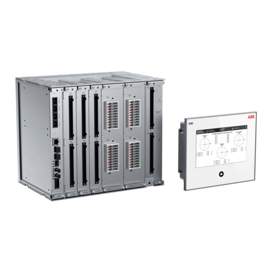
Section 3 1MRS759118 A REX640 overview Section 3 REX640 overview Overview REX640 is a powerful all-in-one protection and control relay for use in advanced power distribution and generation applications with unmatched flexibility available during the complete life cycle of the device – from ordering of the device, through testing and commissioning to upgrading the functionality of the modular software and hardware as application requirements change. -
Page 26: Local Hmi
Section 3 1MRS759118 A REX640 overview GUID-5D4C7B10-17CA-4F59-B9E0-8024CB82CDE8 V1 EN Figure 2: Hardware module slot overview of the REX640 relay 1 Slot markings in enclosure (top and bottom) 2 Ready LED The relay has a nonvolatile memory which does not need any periodical maintenance. The nonvolatile memory stores all events, recordings and logs to a memory which retains data if the relay loses its auxiliary supply. - Page 27 Section 3 1MRS759118 A REX640 overview The LHMI is an accessory for the relay which is fully operational even without the LHMI. GUID-093E5A0B-C7B9-4BEC-8EA6-42EF75793B4F V1 EN Figure 3: Example of a local HMI page The LHMI presents pages in two categories. •...
- Page 28 Section 3 1MRS759118 A REX640 overview Table 3: Power supply module Ready LED and local HMI Home button LED State Power supply module LHMI Home button Alarm acknowledged Ready LED Relay under normal Steady green Steady green operation and LHMI connected Relay’s IRF activated, high frequency blinking...
- Page 29 Section 3 1MRS759118 A REX640 overview 9 10 GUID-01F7FC3E-980D-4670-B195-F8D6D712EF58 V2 EN Figure 4: Menu bar elements Bay name for the relay Page name Edit mode active (parameter editing) Date, time and time synchronization status Page help (visible if help is available for the page) Login button/logged in user indication Local/remote indication USB memory not connected/connected (visible only if USB port is enabled)
-
Page 30: Physical Ports
Section 3 1MRS759118 A REX640 overview Page category Pages Subpages Engineer pages Parameters Testing and Force Functions Commissioning Force Outputs Simulate Inputs View I/O Send Events Secondary Injection Monitoring Protection Measurement Direction Coil Controller Commissioning View GOOSE sending View GOOSE receiving View SMV sending View SMV receiving Relay Status... -
Page 31: Web Hmi
Section 3 1MRS759118 A REX640 overview WHMI connection. Data transfer to a USB stick is enabled via the USB port. By default the USB port is disabled and has to be taken into use with a specific parameter. GUID-D53AE6BA-8746-4796-B1C9-13352190FAEA V1 EN Figure 6: Local HMI connectors 1 USB port... - Page 32 Section 3 1MRS759118 A REX640 overview GUID-85504DBF-C4B1-43B2-A569-A543E61072E7 V2 EN Figure 7: Example view of the Web HMI WHMI offers several functions. The menu tree structure on the WHMI is almost identical to the one on the LHMI. Table 5: Web HMI main groups and submenus Main groups Submenus Description...
-
Page 33: Command Buttons
Section 3 1MRS759118 A REX640 overview 3.4.1 Command buttons Command buttons can be used to edit parameters and control information via the WHMI. Table 6: Command buttons Name Description Enabling parameter editing Disabling parameter editing Filtering the parameter list view Writing parameters to the protection relay Refreshing parameter values Printing out parameters... -
Page 34: User Authorization
Section 3 1MRS759118 A REX640 overview Name Description Viewing all fault records Clearing all fault records Importing settings Exporting settings Selecting all Refreshing the parameter list view Changing the visible setting group Viewing persisting alarms Viewing fleeting alarms Viewing all available alarms Acknowledging the selected alarm Selecting reference phasor Selecting events per page... - Page 35 Section 3 1MRS759118 A REX640 overview Table 7: Device CAM mode values Parameter Values Description Device CAM mode Enabled Authentication done from the CAM server Disabled (Default) Authentication done from the local user account management database For more information, see the cyber security deployment guideline. Local user account management Four factory default user accounts (VIEWER, OPERATOR, ENGINEER and ADMINISTRATOR) have been predefined for the LHMI and the WHMI, each with...
-
Page 36: Station Communication
Section 3 1MRS759118 A REX640 overview For more information on user management and security logging, see the cyber security deployment guideline. For user authorization for PCM600, see the PCM600 documentation. Station communication Operational information and controls are available through a wide range of communication protocols including IEC 61850 Edition 2, IEC 61850-9-2 LE, IEC 60870-5-103, Modbus®... -
Page 37: Connectivity Packages
• Protection and Control IED Manager PCM600 2.9 Hotfix 1 or later • REX640 Connectivity Package Ver.1.0 or later Download connectivity packages from the ABB Web site www.abb.com/relion or directly with Update Manager in PCM600. Modification Sales Modification Sales is a concept that provides modification support for already delivered relays. -
Page 39: Section 4 Using Local Hmi
Section 4 1MRS759118 A Using local HMI Section 4 Using local HMI Logging in Once the LHMI is connected to the relay, tap the LOGIN icon on the menu bar. GUID-BD6B06BD-220C-4A17-B0B5-414044DDEEA8 V2 EN Figure 8: Logging into local HMI Provide the username and password in the dialog box. GUID-347ED860-82CC-4D39-ADAD-9A91ECAE006B V2 EN Figure 9: Providing the user credentials... -
Page 40: Logging Out
Section 4 1MRS759118 A Using local HMI GUID-CFBB72FE-164D-4C88-B802-587159AC3E6A V2 EN Figure 10: Logged in user If logging in fails because all sessions are used, an error message is shown on the login page. GUID-639159B7-5342-4F50-8E93-50AA87187F3D V1 EN Figure 11: Local HMI error message Logging out Tap the username on the menu bar. -
Page 41: Selecting Local Or Remote Use
Section 4 1MRS759118 A Using local HMI GUID-451F8864-473A-4032-B374-EA56D822C709 V2 EN Figure 12: Logging out Changing the password causes immediate logout. If the LHMI and the protection relay have not been paired and there is no user activity for the duration set in Configuration/Web HMI timeout, the LHMI session is logged out. -
Page 42: Identifying Device
Section 4 1MRS759118 A Using local HMI GUID-02DF72B5-D279-4AD2-BFDC-3A41E7DB113F V1 EN Figure 13: Selecting local or remote use To control the protection relay, log in with the appropriate user rights. Identifying device Tap the menu button. Tap Device Information. Product Identifiers are shown by default on the page. Tap HW modules and select Detached LHMI to check the information of the LHMI. -
Page 43: Changing Backlight Brightness And Timeout
Section 4 1MRS759118 A Using local HMI GUID-2FB4C17C-AC3C-48F0-9611-837671105D7F V1 EN Figure 14: Identifying device Changing backlight brightness and timeout Tap the menu button. Tap Parameters. Tap Configuration and then HMI. Tap Edit. Tap Backlight brightness value field. Give the new value and tap OK. Tap Backlight timeout value field to change the backlight timeout. -
Page 44: Changing Setting Visibility
Section 4 1MRS759118 A Using local HMI GUID-EF9F12A1-FF0B-4C9D-AF7A-C661E37F443E V1 EN Figure 15: Changing backlight brightness Changing setting visibility Tap the menu button. Tap Parameters. Tap Settings from the left and select a function. Tap Advanced or Basic on the upper right corner of the page. GUID-A224B139-5638-4CC3-82B5-57EE201B0BC8 V1 EN Figure 16: Changing setting visibility... -
Page 45: Monitoring Relay Status
Section 4 1MRS759118 A Using local HMI Monitoring relay status Tap the menu button. Tap Relay Status. In case of active internal fault or warning, tap More Information. Tap Monitoring to open the monitoring menu. GUID-2249D1E3-5636-45CB-A0DA-B4F95664CD10 V1 EN Figure 17: Selecting self-supervision Changing language Tap the menu button. -
Page 46: Acknowledging Alarms
Section 4 1MRS759118 A Using local HMI • If the LHMI is in sleep mode, tap the Home button to open the alarm list page. • If the LHMI is active, tap the Alarms section on the Overview page or tap the menu button and select View Alarms. -
Page 47: Measurements And Phasor Diagrams
Section 4 1MRS759118 A Using local HMI GUID-5148145D-5DFC-4BE1-9464-259506F268FD V1 EN Figure 18: Acknowledging alarms 4.10 Measurements and phasor diagrams 4.10.1 Viewing measurements The Measurements page is usually one of the Operator pages. Swipe the LHMI screen until the Measurement page is shown. The number of measurements on the Measurement page depends on the LHMI configuration made with GDE. -
Page 48: Viewing Phasor Diagrams
Section 4 1MRS759118 A Using local HMI GUID-1CF47AF4-F9DC-444A-846F-1FF5F0901DFE V1 EN Figure 19: Measurements page 4.10.2 Viewing phasor diagrams Phasor diagrams can be found through the Measurements page. Tap Phasors at the bottom of the page. If more than one phasor diagram page are available, select one from the list opened. -
Page 49: Showing Parameters
Section 4 1MRS759118 A Using local HMI 4.11 Showing parameters Tap the menu button. Tap Parameters. Tap Settings from the left and select a function. GUID-646AF240-14CC-423E-BC50-F34D77F4DDFA V1 EN Figure 21: Showing parameters 4.12 Editing values Tap Edit on the lower left corner of the page to activate the edit mode. A blinking icon on the menu bar indicates that the edit mode is active. -
Page 50: Committing Settings
Section 4 1MRS759118 A Using local HMI GUID-EC70AF08-40AD-4194-BCC7-5786AB4BA976 V1 EN Figure 22: Entering a numeric value GUID-C0DF867D-7E1B-4974-90C2-538A2BF6A1CB V1 EN Figure 23: Entering an alphanumeric value 4.13 Committing settings The blinking icon on the menu bar indicates that at least one parameter value has been changed and storing to the nonvolatile memory is required. - Page 51 Section 4 1MRS759118 A Using local HMI Tapping Reject exits the edit mode without storing the values to the nonvolatile memory. Tapping Cancel closes the dialog box and returns to parameter editing. GUID-23546D2C-4E60-49C4-85B2-EC2D83A602E9 V1 EN Figure 24: Storing required indication on the menu bar GUID-4D497B0B-2204-4394-8441-3F796E43265A V1 EN Figure 25: Storing or rejecting parameter changes...
-
Page 52: Clearing And Acknowledging
Section 4 1MRS759118 A Using local HMI 4.14 Clearing and acknowledging Tap the menu button. Tap Clear. Select the items to be cleared or acknowledged by tapping the corresponding rows. Swipe the list vertically to scroll up and down. Tap Clear from Relay to clear or acknowledge the selected items. GUID-108E4DDD-7C82-494E-82BA-A4CFA3E330A2 V1 EN Figure 26: Clearing and acknowledging... -
Page 53: Viewing Fault Records
Section 4 1MRS759118 A Using local HMI GUID-897674CC-75C8-497A-8CDC-256318BB5049 V1 EN Figure 27: Selecting disturbance records Tap Trigger Recording to manually trigger a recording. 4.16 Viewing fault records The Fault Records page is usually one of the Operator pages. Swipe the LHMI screen until the Fault Records page is shown. The fault records stored in the relay are listed by time stamps on the left of the page. -
Page 54: Selecting Usb Actions
Section 4 1MRS759118 A Using local HMI GUID-93D3FAAC-22DD-4D72-8529-33598E0C308C V1 EN Figure 28: Fault records page 4.17 Selecting USB actions The USB Actions page enables exporting various data from the relay. Device information, events, fault records, parameters and the alarm list are saved in TXT format. -
Page 55: Using Local Hmi Help
Section 4 1MRS759118 A Using local HMI The supported file systems for the USB memory are FAT, FAT32, NTFS, EXT2, EXT3 and EXT4. GUID-3E138C18-BD33-4542-9278-CC3FBDE8030B V1 EN Figure 29: USB Actions page 4.18 Using local HMI help There are two levels of help on the LHMI. •... -
Page 56: Changing Setting Group
Section 4 1MRS759118 A Using local HMI GUID-7DC918C1-0C33-45F1-B1B0-26D3CA53036F V1 EN Figure 30: Page help and parameter help buttons 4.19 Changing setting group Tap the menu button. Tap Parameters. Setting group list is opened by default. Tap Edit. Select the group by tapping the corresponding row and tap Set Active. Tap the icon or Edit. -
Page 57: Controlling
Section 4 1MRS759118 A Using local HMI GUID-B08B11DE-81D9-4F25-A1B7-68536F51FCBE V1 EN Figure 31: Selecting active setting group 4.20 Controlling Controllable objects, such as circuit breakers, disconnectors and earthing switches, can be opened and closed via the single-line diagram. Tap the object in the single-line diagram to select it. to open or to close the selected object. -
Page 58: Bookmarking Pages
Section 4 1MRS759118 A Using local HMI An interlocked object is indicated by the padlock symbol the single-line diagram. If the parameter Breaker operation in Configuration/Control/HMI is set to "After confirmation", a confirmation dialog opens after tapping the control button. The confirmation dialog has a progress bar indicating the Select timeout set for the controllable object. - Page 59 Section 4 1MRS759118 A Using local HMI To go to the Home page from any page, touch the Home button for one second and tap the Go to Home symbol of the Bookmarks page. GUID-05B2DB09-C8A9-4902-9CF7-2DC886AB13B8 V1 EN Figure 34: Bookmarking pages REX640 Operation Manual...
-
Page 61: Section 5 Using Web Hmi
Section 5 1MRS759118 A Using Web HMI Section 5 Using Web HMI Connecting to Web HMI Connection to WHMI can be established using different communication card ports. X0/HMI has always WHMI enabled and is intended to be used with HMI. For other ports, WHMI is enabled by default and can be disabled in the protection relay configuration. - Page 62 Section 5 1MRS759118 A Using Web HMI GUID-3073C31F-B502-46D0-B4C5-CC1F6BA36992 V1 EN Figure 35: Entering username and password to use the Web HMI If logging in fails because all sessions are used, an error message is shown on the login page. GUID-0753822C-8EB6-464F-92C6-CD9044B4F4C3 V1 EN Figure 36: Web HMI error message Select the role if an additional view opens.
-
Page 63: Logging Out
Section 5 1MRS759118 A Using Web HMI GUID-FA4BF888-E17C-474F-904B-FC270EC3F77D V1 EN Figure 37: Selecting user role The progress indicator is displayed until the WHMI opens and the dashboard view is shown. It is recommended to disable the auto-complete feature, which is usually enabled by default, in the Web browser to prevent the usernames and passwords from being stored in the browser's cache. -
Page 64: Identifying Device
Section 5 1MRS759118 A Using Web HMI Identifying device The Information menu includes detailed information about the device, for example, revision and serial number. Select Device on the menu bar. Select Information. Click a submenu to see the data. GUID-FD3BB229-146B-4331-AC35-BBBB74E2FCDB V1 EN Figure 38: Viewing device information Viewing dashboard... -
Page 65: Viewing Self-Supervision
Section 5 1MRS759118 A Using Web HMI Viewing self-supervision Select Device on the menu bar. Select Self-Supervision. The Self-Supervision view shows currently active internal faults and warnings. GUID-D41600D4-9EE8-489D-AF97-702E5C7D1D4C V1 EN Figure 40: Self-supervision: one internal fault is currently active Changing language The active language of the Web server session is indicated in the caption of the menu bar button. -
Page 66: Alarms
Section 5 1MRS759118 A Using Web HMI Alarms 5.7.1 Viewing alarm list Select Recordings on the menu bar. Select Alarm List to access the alarm list. Click one of the three buttons to select an alarm view. • The Persisting Alarms view lists the active alarms. •... -
Page 67: Acknowledging Alarms
Section 5 1MRS759118 A Using Web HMI GUID-D5D4CDDF-282D-4D5C-ADCA-FE81D2E07E46 V1 EN Figure 44: Viewing all available alarms 5.7.2 Acknowledging alarms Select Recordings on the menu bar. Select Alarm List. Select the alarm view. Select the alarms using check boxes. Click Acknowledge. GUID-06D0F22E-32D2-4E1C-A345-3D6450C53137 V1 EN Figure 45: Acknowledging alarms... -
Page 68: Measurements And Phasor Diagrams
Section 5 1MRS759118 A Using Web HMI Measurements and phasor diagrams 5.8.1 Viewing measurements Select Measurements on the menu bar. Select Measurements from the drop-down list. GUID-27A910D5-2452-4D15-8A3F-B55B33617DAA V1 EN Figure 46: Viewing measurements Measurements are also displayed in the Dashboard view. 5.8.2 Viewing phasor diagrams Select Measurements on the menu bar. - Page 69 Section 5 1MRS759118 A Using Web HMI GUID-DDD4933C-E175-44DE-8E25-6CE20E9BE0EE V1 EN Figure 47: Monitoring phasors Select the phasor from the drop-down list on the Phasor Diagrams page to view GUID-71B6B2BE-931C-4B8C-B7A2-877FF145E503 V1 EN Figure 48: Selecting the phasor Select Custom from the drop-down list on the Phasor Diagrams page to open the dialog with the phasor list.
- Page 70 Section 5 1MRS759118 A Using Web HMI GUID-FECB1994-259C-4794-9734-9E2EA9CEB590 V1 EN Figure 49: Selecting the custom phasors In the Custom dialog, select the phasors to be monitored and click Close. GUID-BE7052C7-4B31-42ED-B434-21AFBCA6A252 V1 EN Figure 50: Editing custom phasor list Click the Select reference button to select a reference phasor and then click Close.
-
Page 71: Viewing Monitoring
Section 5 1MRS759118 A Using Web HMI GUID-9E92B283-0E03-41FD-842D-ECEB1BD64EBF V1 EN Figure 51: Selecting the reference phasor WHMI measurements and phasor diagrams follow LHMI definitions and can be edited with Graphical Display Editor in PCM600. Viewing monitoring Select Device on the menu bar. Select Monitoring from the drop-down list. -
Page 72: Viewing Single-Line Diagram
Section 5 1MRS759118 A Using Web HMI GUID-02091769-FD61-4FA8-BE30-9234633F7313 V1 EN Figure 52: Monitoring data 5.10 Viewing single-line diagram The single-line diagram is displayed on the dashboard and the Single Line Diagram page. If there are more than one page, the first page is displayed and the others are included in the drop-down list. -
Page 73: Showing Parameters
Section 5 1MRS759118 A Using Web HMI 5.11 Showing parameters Some function blocks have a function-specific ON/OFF setting. When the function setting is "off", all settings are hidden and when the function setting is "on", all settings are visible based on the other visibility and hiding rules. Switch a function block on or off via the Operation parameter under the function block. -
Page 74: Editing Values
Section 5 1MRS759118 A Using Web HMI GUID-CC9922C3-0D8F-4AC2-B062-E35118D7E9E6 V1 EN Figure 55: Enabling settings The Parameter List page offers filtering functionality where only chosen parameters are displayed, saved or printed. There are various options for filtering. • Enabled Settings hides settings of disabled function blocks. This option is checked by default. - Page 75 Section 5 1MRS759118 A Using Web HMI GUID-124044A0-DD9A-4049-B358-73A3AD2FB86B V1 EN Figure 56: Enable writing to edit a value The selected setting group is shown in the Setting Group drop-down list and the setting group parameters are listed on page. The active setting group is indicated with an asterisk *.
-
Page 76: Committing Settings
Section 5 1MRS759118 A Using Web HMI GUID-474F95AB-AED1-412D-9661-7162768F316B V1 EN Figure 58: Error indicating that the entered value is incorrect If writing values fails, an error message is displayed. GUID-1FD447D8-367B-4CD6-9D7A-051D55A925A6 V1 EN Figure 59: Error indicating that the values were not written to the protection relay Commit the settings. - Page 77 Section 5 1MRS759118 A Using Web HMI GUID-0694CCC5-3911-4036-A6D0-33CC9BFB1C3B V1 EN Figure 60: Writing values to the protection relay Click Store Changes to store the values to the flash memory. Click Reject Changes to cancel saving settings. If the parameter has an edit-copy, the original parameter value is restored. If the parameter does not have an edit-copy, the edited parameter value remains visible until the protection relay is rebooted.
-
Page 78: Clearing And Acknowledging
Section 5 1MRS759118 A Using Web HMI 5.14 Clearing and acknowledging Reset, acknowledge or clear all messages and indications, including LEDs and latched outputs as well as registers and recordings, in the Clear page. Select Device on the menu bar. Select Clear from the drop-down list. -
Page 79: Accessing Event View
Section 5 1MRS759118 A Using Web HMI 5.15 Accessing event view The event view contains a list of events produced by the application configuration. When the event page is opened, it displays up to 20 latest events at one time. The event list is updated automatically. -
Page 80: Accessing Disturbance Record View
Section 5 1MRS759118 A Using Web HMI GUID-E07826B1-9CB6-4D3E-AFB8-B4A93045F600 V1 EN Figure 65: Viewing events To save the events as .txt or .csv files, click Export and select the file format from the drop-down list. The CSV file can be opened with a spreadsheet program such as OpenOffice.org Calc or Microsoft Excel. -
Page 81: Saving Disturbance Records
Section 5 1MRS759118 A Using Web HMI 5.16.1 Saving disturbance records Select Recordings on the menu bar. Select Disturbance Records from the drop-down list. To save the disturbance record files, click the Export button in the Export Files column of the record. Both disturbance record files CFG and DAT are saved at once. -
Page 82: Deleting Disturbance Records
Section 5 1MRS759118 A Using Web HMI GUID-B4E57853-D0C6-43B8-8779-3DF8F19FCE39 V1 EN Figure 70: Triggering recording - progress bar 5.16.3 Deleting disturbance records Select Recordings on the menu bar. Select Disturbance Records from the drop-down list. Delete records in one of the alternative ways. •... -
Page 83: Exporting Load Profile Records
Section 5 1MRS759118 A Using Web HMI To clear all fault records from the relay, click Clear All. This can be done only when the fault record list view is shown. To print all fault records, click Print when the fault record list view is shown. To print only one record, open it in the details view and click Print. -
Page 84: Importing And Exporting Of Settings
Section 5 1MRS759118 A Using Web HMI 5.19 Importing and exporting of settings The relay's setting parameters can be imported and exported in the XRIO file format. 5.19.1 Exporting settings The relay's setting parameters can be exported in XRIO file format. Select Import/Export on the menu bar. - Page 85 Section 5 1MRS759118 A Using Web HMI The exporting and importing of settings is sensitive to the protection relay content. Settings are exported and imported for one protection relay at a time. The export files of a specific protection relay can be exchanged between PCM600, WHMI and the actual physical protection relay.
-
Page 86: Exporting Report Summary
Section 5 1MRS759118 A Using Web HMI Click Cancel to cancel the import. Both the WHMI and the relay revert to the settings in use prior to the import. GUID-D786C9E5-4FD0-4925-A0C7-8EC0E4CC4FC3 V1 EN Figure 77: Writing parameter settings GUID-46164DE3-E805-4592-AA9B-6272DFD0C115 V1 EN Figure 78: Parameter settings written to relay Only editable parameters are written to the relay during the... -
Page 87: Using Web Hmi Help
Section 5 1MRS759118 A Using Web HMI GUID-96C179E2-139F-44B7-99FF-E397D475FABC V1 EN Figure 79: Report Summary page 5.21 Using Web HMI help The context-sensitive WHMI help provides information on a single parameter, for example. • Move the mouse over to display the help dialog box. GUID-C07C904F-EF9A-4A1C-BC49-032B50759482 V1 EN Figure 80: Opening the Web HMI help... -
Page 89: Section 6 Troubleshooting
Inspect the protection relay visually. • Inspect the protection relay visually to find any physical error causes. • If you can find some obvious physical damage, contact ABB for repair or replacement actions. Check whether the error is external or internal. •... -
Page 90: Checking Time Synchronization
Section 6 1MRS759118 A Troubleshooting Table 8: Front communication LEDs Communication ok Uplink Steady green light Communication Flashing yellow light 6.1.3.2 Checking time synchronization • Check the time synchronization via LHMI in Main Menu/Relay Status/ Monitoring/IED status/Time synchronization. 6.1.4 Checking local HMI connectivity If the connection between the LHMI and the relay is lost, check the following. -
Page 91: Internal Faults
Section 6 1MRS759118 A Troubleshooting GUID-C2262ADD-640C-4F59-B584-BE03A1C43F95 V1 EN Figure 81: Relay self-supervision status on local HMI On the WHMI, the self-supervision status is available under Device menu. The top right LED indicates the relay status. GUID-C1CB83B9-C8C1-4FBC-AD6A-664E7684ACE4 V1 EN Figure 82: Relay self-supervision status on Web HMI In addition, the last boot reason and time are shown on both LHMI and WHMI. - Page 92 The internal fault code indicates the type of internal relay fault. When a fault appears, the code must be recorded so that it can be reported to ABB customer service. More details about the active internal fault are found on the Relay Status page. On the LHMI, the internal fault state is indicated with a red LED.
- Page 93 Section 6 1MRS759118 A Troubleshooting GUID-2BBCEC19-B8F1-4F8D-8EB3-1A5B376EBE34 V1 EN Figure 84: Internal fault state indicated with red LED More Information shows all active faults and the corresponding fault codes. In addition, a recovery procedure is described. GUID-6FAA2FE1-AA4A-4DF4-B1CE-55F8B00BDE33 V1 EN Figure 85: More information about the fault REX640 Operation Manual...
- Page 94 Section 6 1MRS759118 A Troubleshooting On the WHMI, internal fault information is shown under Self-Supervision Status. GUID-D4B0F232-B2CC-49A7-9C54-5F880CDE4D34 V1 EN Figure 86: Internal fault information on Web HMI Table 9: Internal fault indications and codes Fault indication Fault code Additional information System error An internal system error has occurred.
- Page 95 Section 6 1MRS759118 A Troubleshooting Fault indication Fault code Additional information Conf.error,slot E Module in slot E is wrong type, is missing, does not belong to original configuration or module firmware is faulty. Conf.error,slot A2 Module in slot A2 is wrong type, is missing, does not belong to original configuration or module firmware is faulty.
-
Page 96: Warnings
LHMI Home button flashes red. If a warning appears, record the name and code so that it can be provided to ABB customer service. On the LHMI, an active warning is indicated with a yellow LED. More information about the warning and recovery options can be accessed by tapping More Information. - Page 97 Section 6 1MRS759118 A Troubleshooting GUID-D35FF83D-0266-4E9E-A056-E1276C32AEA1 V1 EN Figure 88: More information about the warning Table 10: Warning indications and codes Warning indication Warning code Additional information Watchdog reset A watchdog reset has occurred. Power down det. The auxiliary supply voltage has dropped too low.
-
Page 98: Power Supply Module Ready Led And Local Hmi Home Button Led
Section 6 1MRS759118 A Troubleshooting Warning indication Warning code Additional information Comm. channel down Redundant Ethernet (HSR/ PRP) communication interrupted Settings mismatch Mismatch between parameter settings and application configuration Protection comm. Error in protection communication ARC1 cont. light A continuous light has been detected on the ARC light input ARC2 cont. -
Page 99: Correction Procedures
Section 6 1MRS759118 A Troubleshooting State Power supply module LHMI Home button Alarm acknowledged Ready LED Process related alarm Steady green LF blinking red active Process related alarm Steady green Steady red active Process related alarm Steady green LF blinking red has been active earlier, but is not any more active. -
Page 100: Identifying Relay Application Problems
Log in as administrator to reset the users' passwords. For more information on user management, see Cyber Security Deployment Guideline. If the administrator password is lost, contact ABB's technical customer support to retrieve the administrator level access. 6.3.4 Identifying relay application problems •... - Page 101 In case of permanent faults, the measurement chain should be checked to remove the origin of the faulty measurement data. In case of persistent faults originating from protection relay's internal faults, contact ABB for repair or replacement actions. REX640 Operation Manual...
-
Page 103: Section 7 Commissioning
Section 7 1MRS759118 A Commissioning Section 7 Commissioning Commissioning checklist Familiarize yourself with the protection relay and its functionality before you start the commissioning work. • Ensure that you have all the needed station drawings such as single line and wiring diagrams. -
Page 104: Checking Ct Circuits
Section 7 1MRS759118 A Commissioning 7.2.2 Checking CT circuits Check that the wiring is in strict accordance with the supplied connection diagram. The CTs must be connected in accordance with the connection diagram of the project, both with regards to phases and polarity. The following tests are recommended for every primary CT or CT core connected to the protection relay. -
Page 105: Checking Binary Input And Output Circuits
Section 7 1MRS759118 A Commissioning Correct possible errors before continuing to test the circuitry. Test the circuitry. • Polarity check • VT circuit voltage measurement (primary injection test) • Earthing check • Phase relationship • Insulation resistance check The polarity check verifies the integrity of circuits and the phase relationships. The polarity must be measured as close to the protection relay as possible. -
Page 106: Authorizations
Section 7 1MRS759118 A Commissioning Authorizations 7.3.1 User authorization The user categories have been predefined for the LHMI and WHMI, each with different rights and default passwords. Passwords are settable for user accounts in all roles. Only the following characters are accepted. -
Page 107: Setting Protection Relay And Communication
Policy change and configuration is not allowed when the protection relay is in offline mode in PCM600. If the last ADMINISTRATOR password is lost, contact ABB's technical customer support to retrieve the administrator level access. Setting protection relay and communication 7.4.1... -
Page 108: Communication Between Pcm600 And Protection Relay
Section 7 1MRS759118 A Commissioning To configure the physical connection and the IP addresses: Set up or get the IP addresses of the protection relays. Set up the PC for a direct link or connect the PC or workstation to the network. Configure the IP addresses in the PCM600 project for each protection relay. -
Page 109: Communication Settings
Section 7 1MRS759118 A Commissioning Port number Type Default state Description Closed Modbus TCP 20000 Closed DNP3 TCP 20000 Closed DNP3 UDP 1468 Closed Closed 7.4.2 Communication settings 7.4.2.1 Ethernet ports The protection relay allows the use of a secondary IP address for the station ports on the communication modules COM1001...COM1003. -
Page 110: Protocol Control
Section 7 1MRS759118 A Commissioning ARC1001 COM1001 COM1002 COM1003 GUID-A553A618-23A2-4128-9B0C-76A3C5CF123E V1 EN Figure 89: Ethernet modes with Network 1 and Network 2 1 Network 1 2 Network 1/Network 2 7.4.2.2 Protocol control It is possible to allow or block different protocols for different network interfaces in the protection relay using the parameters in Configuration/Communication/ Protocols/Network1, Configuration/Communication/Protocols/Network2 and Configuration/Communication/Protocols/HMI Port. -
Page 111: Protocol Write Access Rights
Section 7 1MRS759118 A Commissioning All protocols are allowed for each network by default, and can be separately disabled. Table 15: Protocol control in the protection relay Parameter Options Description Configuration/Communication/ Denies FTP and FTPS Protocols/Network1/FTP On (Default) Allows FTP and FTPS Secure Allows FTPS only Configuration/Communication/... -
Page 112: Physical Locations Of The Serial Channels
Section 7 1MRS759118 A Commissioning Table 16: Protocol write access in the protection relay Parameter Options Description Configuration/Authorization/ FTP write access denied for Network1/FTP write access Network 1 On (Default) FTP write access allowed for Network 1 Configuration/Authorization/ IEC 61850 MMS write access Network1/MMS write access denied for Network 1 On (Default) - Page 113 Section 7 1MRS759118 A Commissioning Table 17: Connector X8 signals Pin No Pin name Description Alternative EARTH GNDC GND connected to earth via 1nF capacitor IRIG-B - ISOL2_GND IRIG-B + ISOL_GND RS485 GND RS485 B1/- 2-wire - , COM1 4-wire TX pair, COM1 RS485 A1/+ 2-wire + , COM1 4-wire TX pair, COM1...
-
Page 114: Assigning Of A Serial Communication Protocol To A Com Serial Port
Section 7 1MRS759118 A Commissioning 7.4.2.5 Assigning of a serial communication protocol to a COM serial port The settings of the serial communication protocol instance include a setting parameter, called either Port or Serial port, which is used to select the COM1 or COM2 setting. -
Page 115: Defining Ethernet Port Settings
Section 7 1MRS759118 A Commissioning Table 20: Diagnostic counters and indications Counters Description Characters received Counts all incoming non-erroneous characters. This counter operates regardless of whether the serial driver is set to detect a whole protocol link frame or just separate characters. Frames received Counts all protocol-specific non-erroneous frames received. -
Page 116: Defining Serial Port Settings
Section 7 1MRS759118 A Commissioning • IP address • Subnet mask • Default gateway of the optional rear port Ethernet connector 7.4.2.8 Defining serial port settings Select Configuration/Communication/COM1 or COM2. Define the settings for the serial port. It is possible to change the general serial communication parameters per port. Select fiber or galvanic mode with the proper baud rate. -
Page 117: Connecting Local Hmi To A Relay Through Station Network
Section 7 1MRS759118 A Commissioning 7.4.3.2 Connecting local HMI to a relay through station network PCM600 or WHMI can be used to read the network settings of the relay's station port via Configuration/Communication/Ethernet/Network address. On the LHMI, tap Network Settings to configure the network settings of the main unit port. - Page 118 Section 7 1MRS759118 A Commissioning GUID-425A7E2C-C0C3-48FE-A6CA-5EE34C856D21 V1 EN Figure 92: Configuring the network settings of the main unit port Tap Apply and close the Network Settings page. Connect a network cable between the LHMI and the relay station port or network switch.
-
Page 119: Pairing Local Hmi With Relay
Section 7 1MRS759118 A Commissioning GUID-680D069A-B381-4415-BDE5-CA7A022D297B V1 EN Figure 93: Typing the relay IP address 7.4.3.3 Pairing local HMI with relay To enable proper connection and functionality between the LHMI and a relay they need to be paired. Connect the LHMI to the relay. In the confirmation window, tap Trust this Relay. - Page 120 Section 7 1MRS759118 A Commissioning GUID-70F11828-798E-4894-BDC1-9C9B5F8595E3 V1 EN Figure 94: Confirming the relay connection A page for initiating the pairing opens. To initiate pairing, login as administrator. GUID-43DF8EC5-3C10-4F7B-8E87-83F6C6E7A4F1 V1 EN Figure 95: Administrator login required Tap Pair. REX640 Operation Manual...
-
Page 121: Setting System Time And Time Synchronization
Section 7 1MRS759118 A Commissioning GUID-A25A7168-2661-4583-84C3-8DE812AE30E4 V1 EN Figure 96: Pairing the local HMI with the relay After successful pairing, the LHMI Home page opens. If the pairing is skipped, the LHMI can be used for monitoring purposes only. Pairing can be initiated later via the drop-down menu. -
Page 122: Testing Of Protection Relay Operation
Section 7 1MRS759118 A Commissioning Table 22: Possible date values for DST change on Sunday Day of the DST shift DST on/off date (day) First Sunday of the month Second Sunday of the month Third Sunday of the month Fourth Sunday of the month Last Sunday, if the month has 30 days Last Sunday, if the month has 31 days For example, if DST on time shift occurs on the last Sunday in March, at 03:00... -
Page 123: Selecting Ied Test Mode
Section 7 1MRS759118 A Commissioning 7.5.1 Selecting IED test mode The test mode can be activated using the LHMI. The Home button is flashing green at low frequency to indicate that the test mode is activated. By default, the test mode can only be changed from the LHMI. -
Page 124: Testing I/O Interface
Section 7 1MRS759118 A Commissioning GUID-1ADCE271-EB04-4FFB-B703-268B42286FD0 V1 EN Figure 98: Home page for Testing and Commissioning pages 7.5.2.1 Testing I/O interface On the View I/O page, monitor the status of digital inputs and outputs and analog inputs. 1.1. Tap the module on the page to open the module-specific page. 1.2. - Page 125 Section 7 1MRS759118 A Commissioning GUID-153062F6-F84E-4D46-8F11-55AE26783C68 V1 EN Figure 100: Force Outputs page 2.1. Tap the module on the page to open the module-specific page. 2.2. Tap to scroll over the different modules. 2.3. On the module-specific page, select state On or Off for the selected output channel and tap Force.
- Page 126 Section 7 1MRS759118 A Commissioning 3.1. Tap the module on the page to open the module-specific page. 3.2. Tap to scroll over the different modules. 3.3. On the BIO module specific page, select On or Off for the selected channel and tap Simulate.
-
Page 127: Testing Functions
Section 7 1MRS759118 A Commissioning All current and voltage input signals (channels) share the same phase angle value, that is, they are in phase. 7.5.2.2 Testing functions On the Force Functions page, activate or deactivate an output signal for protection or other function in one of the alternative ways. •... -
Page 128: Checking Goose Data
Section 7 1MRS759118 A Commissioning GUID-94687084-2B9A-45D4-AD4A-D022CA593124 V1 EN Figure 105: Send Events page 7.5.2.3 Checking GOOSE data On the GOOSE Receiving page, check the GOOSE data that the relay subscribes from the Ethernet network. The left side of this page shows a list of devices that send GOOSE messages to the relay. - Page 129 Section 7 1MRS759118 A Commissioning GUID-F1982C6F-DDCB-4963-A03F-97407D891C4F V1 EN Figure 106: GOOSE Receiving page On the GOOSE Sending page, check the status of the relay's configured GOOSE control blocks and the values of the sent data. The left side of this page shows a list of the devices where the relay sends GOOSE messages.
-
Page 130: Checking Smv Data
Section 7 1MRS759118 A Commissioning 7.5.2.4 Checking SMV data On the SMV Receiving page, check the sampled values data that the relay subscribes from the Ethernet network. The left side of this page shows a list of devices that send SMV messages to the relay. -
Page 131: Selecting Internal Fault Test
Section 7 1MRS759118 A Commissioning GUID-17BB9307-FD1C-439C-83C7-FCF43D481692 V1 EN Figure 109: SMV Sending page 7.5.3 Selecting internal fault test The internal fault may be tested by using the LHMI. When enabling the test, the internal relay fault output contact is activated. See the technical manual for the internal relay fault output contact location. -
Page 132: Abb Product Data Registration
If the IED blocked or IED test and blocked mode is not cancelled, it remains on and the Home button remain flashing. ABB Product Data Registration The ABB Product Data Registration feature traces composition changes in the protection relay's SW or HW. Traceability allows better support and maintenance possibilities. -
Page 133: Operation Manual
Section 7 1MRS759118 A Commissioning The number of composition and setting changes can be seen from the Composition changes parameter in Monitoring/IED status. LCT-generated events are reported as a bit-masked value (change flags); for example, value 9 means that hardware and site identifier changes have been done to the relay. Table 24: LCT-generated events Description... -
Page 135: Section 8 Glossary
Section 8 1MRS759118 A Glossary Section 8 Glossary Alternating current Active directory Central activity logging Centralized account management CAT 5 A twisted pair cable type designed for high signal integrity CAT 6 Cable standard for gigabit Ethernet and other network protocols that is backward compatible with CAT 5/5e and CAT 3 cable standards Configuration file... - Page 136 Section 8 1MRS759118 A Glossary FTPS FTP Secure Graphical Display Editor in PCM600 Ground/earth GOOSE Generic Object-Oriented Substation Event High frequency Human-machine interface High-availability seamless redundancy HTTPS Hypertext Transfer Protocol Secure Hardware International Electrotechnical Commission IEC 61850 International standard for substation communication and modeling IEC 61850-9-2 A communication protocol based on the IEC 61850...
- Page 137 Section 8 1MRS759118 A Glossary Modbus RTU Link mode using 8-bit binary characters Network control center 1. Personal computer 2. Polycarbonate Product connectivity level PCM600 Protection and Control IED Manager Precision Time Protocol Random access memory RJ-45 Galvanic connector type RoHS Restriction of hazardous substances Read-only memory...
- Page 140 — ABB Distribution Solutions Distribution Automation P.O. Box 699 FI-65101 VAASA, Finland Phone +358 10 22 11 www.abb.com/mediumvoltage www.abb.com/relion © Copyright 2019 ABB. All rights reserved.
Need help?
Do you have a question about the RELION REX640 and is the answer not in the manual?
Questions and answers