ABB REX615 Installation Manual
Hide thumbs
Also See for REX615:
- Operation manual (152 pages) ,
- Installation manual (108 pages) ,
- Manual (59 pages)
Table of Contents
Advertisement
Advertisement
Table of Contents

Related Manuals for ABB REX615


Summary of Contents for ABB REX615
- Page 1 — Relay Retrofit Program for SPACOM to REX615 Installation Manual...
- Page 3 Document ID: 4TLB000504 Issued: 2024-04-05 Revision: A © Copyright 2024 ABB. All rights reserved...
- Page 4 Copyright ABB is the owner of the copyright in this document. This document or any parts thereof must not be reproduced or copied without the written permission from ABB and the contents thereof must not be used to any unauthorized purpose.
- Page 5 Other than under explicit contractual commitments, in no event shall ABB be responsible or liable for any loss or damage resulting from the use of this manual or the application of the equipment.
- Page 6 Conformity See the REX615 Installation Manual for detailed information on Conformity.
- Page 7 Safety information Dangerous voltages can occur on the connectors, even though the auxiliary voltage has been disconnected. Non-observance can result in death, personal injury or substantial property damage. Only a competent electrician is allowed to carry out the electrical installation. National and local electrical safety regulations must always be followed.
-
Page 8: Table Of Contents
18 Preparing a cutout for REX615......................25 Flush mounting the REX615.........................27 Connecting....................30 Required tools............................30 Connecting functional earthing......................30 Finalization of the wirings and connecting the pre-wired terminals to REX615...... 32 Energizing the protection relay......................33 Installation Manual... - Page 9 Contents Accessories and ordering data..............34 Glossary....................35 Installation Manual...
-
Page 10: Introduction
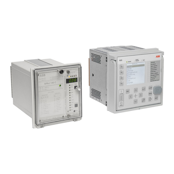
This manual The installation manual contains instructions on how to replace the old generation SPACOM relay with new protection and control relay REX615 by using the relay retrofit connectors and changing the wirings. The manual provides procedures for mechanical and electrical installation. The chapters are organized in chronological order in which the REX615 relay, together with relay retrofit connectors, should be installed. -
Page 11: Document Revision History
Relay Retrofit Program for SPACOM to REX615 Product Guide 4TLB000502 REX615 Installation Manual 2NGA001864 See the SPACOM relays and REX615 relay documentation for detailed technical information on the relays. Product series- and product-specific www.abb.com/ manuals can be downloaded from the ABB website:... -
Page 12: Document Conventions
Introduction 4TLB000504 A 1.4.2 Document conventions A particular convention may not be used in this manual. • Abbreviations and acronyms are spelled out in the glossary. The glossary also contains definitions of important terms. • Parameter names are shown in italics. Operation setting. -
Page 13: Environmental Aspects
4TLB000504 A Environmental aspects Environmental aspects Sustainable development Sustainability has been taken into account from the beginning of the product design including the pro-environmental manufacturing process, long lifetime, operation reliability and disposing of the protection relay with retrofit connectors and other deliverables. The choice of materials and suppliers has been made according to the EU RoHS (2011/65/EU). - Page 14 Environmental aspects 4TLB000504 A Table 2: Materials of the protection relay parts, including retrofit connectors and other deliverables Protection relay Parts Material Case Metallic plates, parts and screws Steel Plastic parts , LCP Electronics plug in module Various Plug-in unit of protection relay Electronics plug in modules Various Electronics LHMI module...
-
Page 15: Unpacking, Inspection And Storing
• 4 pcs of M3 x 8 mm screw T10 (for the X100 and X110 connectors). • Installation support frame (optional) These all items require careful handling. See also the REX615 Installation Manual for information related to unpacking, inspection and storing of protection relay. -
Page 16: Checking Delivery Items
Checking delivery items Check that all items are included in the delivery in accordance with the delivery documents. Notify ABB immediately if there are any discrepancies in relation to the delivery documents. Table 3: SPACOM relay types, connectors, and other delivery items... -
Page 17: Returning A Product Damaged In Transit
Returning a product damaged in transit If damage has occurred during transport, appropriate actions must be taken against the latest carrier. Please inform the nearest ABB office or representative. Notify ABB immediately if there are any discrepancies in relation to the delivery documents. Storing If the products are stored before installation, it must be done in the original transport casing in a dry and dust free place. -
Page 18: Mounting
• T25 Torx screwdriver for detaching the fixing parts of the existing SPACOM relay • T25 Torx screwdriver for mounting the REX615 relay • T20 Torx for connecting the protective earthing of REX615 relay • PH1 for CT/VT terminals (screw-compression type) •... -
Page 19: Detaching The Spacom Relay And Making The Re-Wiring Of Retrofit Connectors With Installation Support Frame
It is recommended to inspect relay wiring first for any discrepancies. REX615 relays are delivered from the factory with suitable retrofit connectors installed on the relay terminals. Remove the retrofit connectors X100 and X110, and also X130 if it is part of the delivery. - Page 20 Mounting 4TLB000504 A Figure 4: Installing the retrofit connectors to the corresponding terminals of the installation support frame Remove the orange color connector, wherever applicable, from the existing SPACOM relay and cut the cable ties to get sufficient space for the installation support frame.
- Page 21 4TLB000504 A Mounting Loosen the fixing screw of the SPACOM relay to temporarily mount installation support frame by using the holes on the frame. Aften inserting the installation support frame, tighten the fixing screws again. Figure 6: Temporary mounting of the installation support frame to the SPACOM relay The retrofit connectors are marked on the top based on the existing SPACOM relay terminal numbers.
- Page 22 Mounting 4TLB000504 A Remove the secondary wires from the existing SPACOM relay. Figure 7: Removing the secondary wires from the existing SPACOM relay Installation Manual...
- Page 23 4TLB000504 A Mounting Connect the wires on the corresponding terminal of retrofit connector by following the terminal numbering. Figure 8: Connecting the wires on the corresponding terminal of retrofit connector by following the terminal numbering Figure 9: Separate push-in type terminals are provided for instrument transformers (CTs and VTs) secondary wires temporary connection Installation Manual...
- Page 24 Mounting 4TLB000504 A Remove the wires also from the existing orange color connector, if included, and connect the wires on the corresponding terminal of retrofit connector by following the terminal numbering. Figure 10: a) Removing wires also from existing orange color connector, if included, and b) connecting the wires on the corresponding terminal of retrofit connector by following the terminal numbering After the re-wiring is completed, loosen the fixing screw, remove the installation...
-
Page 25: Preparing A Cutout For Rex615
Figure 13: Taking out the SPACOM relay from the existing location Preparing a cutout for REX615 Increase the existing SPACOM relay panel cutout for new REX615 relay by using the cutting tool and dedicated cutting head for SPACOM 100 series relays. - Page 26 Protect the personnel and the panel door from flying offcuts. There are four options to widen the SPACOM 100 series relay cutout for REX615. Figure 14 illustrates the cutting order options.
-
Page 27: Flush Mounting The Rex615
4TLB000504 A Mounting Figure 15: Cutting tool with dedicated cutting head Figure 16: Making the cutout for REX615 Installation Manual... - Page 28 Mounting 4TLB000504 A Flush mounting the REX615 Refer to the REX615 Installation Manual for the detaching and installing plug-in unit part from the REX615. All the mounting elements are integrated in the protection relay. Requirements for installation of REX615 protection and control relay: •...
- Page 29 The allowed range for the fixing screws’ tightening torque is 0.7…1 Nm. Figure 18: Flush mounted case, tightening the M5 fixing screws Install the plug-in unit into the case. Figure 19: Installing the plug-in unit of the REX615 relay into the case Installation Manual...
-
Page 30: Connecting
Connecting 4TLB000504 A Connecting Required tools Refer to the REX615 Installation Manual Only use a screwdriver and insert bits for Phillips (PH 1) cross-recessed head screws (M3.5) when handling CT/ VT terminals of screw-compression type. Max. ø5.5 mm (0.22 inches) Max. -
Page 31: Connecting Functional Earthing
4TLB000504 A Connecting Connecting functional earthing The earth lead must be at least 6.0 mm . If the earth lead is long, the cross section of the wire must be increased. Use fine copper wire as the earth lead. Use either the existing SPACOM relay earth lead or a newly delivered earth lead. -
Page 32: Finalization Of The Wirings And Connecting The Pre-Wired Terminals To Rex615
Open the screw-compression type terminals before inserting any wires. The CT/VT terminals are closed at the time of delivery. Check the terminal diagram of REX615 from the Installation and Technical Manuals of REX615. See the specific card variants from the Application manual of REX615. -
Page 33: Energizing The Protection Relay
Connect the pre-wired X100, X110 connectors and also X130, if it’s part of the delivery, to the REX615 relay by following the markings and numbering. Figure 24: Connecting the pre-wired X100, X110 and X130 connectors to REX615 Energizing the protection relay See the detailed information about energizing the protection relay from the REX615 Installation Manual. - Page 34 Accessories and ordering data 4TLB000504 A Accessories and ordering data Table 4: Order codes for Relay Retrofit Program for SPACOM to REX615 SPACOM relay type to be retrofitted Order code for Relay Retrofit Program Order code for Relay Retrofit Program...
- Page 35 4TLB000504 A Glossary Glossary Current transformer Liquid crystal polymer Polybutylene terephthalate Polyamide Polycarbonate RoHS Restriction of the use of certain hazardous substances in electrical and electronic equipment Voltage transformer Installation Manual...
- Page 36 — ABB Oy Electrification Service P.O. Box 503 FI-65101 VAASA, Finland www.abb.com/service www.abb.com/mediumvoltage © Copyright 2024 ABB. All rights reserved.
Need help?
Do you have a question about the REX615 and is the answer not in the manual?
Questions and answers