
Related Manuals for Frick QUANTUM 3


Summary of Contents for Frick QUANTUM 3
-
Page 1: Control Panel
S90-010 M/JUL 2002 File: SERVICE MANUAL - SECTION 90 Replaces: S90-010 M/JUL 01 Dist: 3, 3a, 3b, 3c MAINTENANCE ® FRICK QUANTUM™ COMPRESSOR CONTROL PANEL VERSION 4.5x... -
Page 2: Table Of Contents
® S90-010 M FRICK QUANTUM™ COMPRESSOR CONTROL PANEL Page 2 MAINTENANCE Table of Contents QUANTUM™ CONTROLLER BOARD IDENTIFICATION ..................5 Introduction................................5 Quantum™ 3 ............................... 5 Quantum™ 4 ..............................5 Troubleshooting ............................5 The Quantum™ Control Panel ........................5 General Information ..........................5 What To Do Before Calling The Factory .................... - Page 3 Display Replacement ............................34 Display Assembly Component Replacement Guide ..................34 POINT-TO-POINT FIELD WIRING DIAGRAM ......................35 TROUBLESHOOTING A PROBLEM THAT APPEARS UNEXPLAINABLE ............36 ® TROUBLESHOOTING CHART FOR FRICK QUANTUM™ CONTROL PANEL..........37 COMPRESSOR MODEL DIFFERENCES .......................40 SETPOINT DATA SHEETS .............................41 Factory Setup..............................41 Panel Setup................................43 Calibration ................................46...
- Page 4 RECOMMENDED SPARE PARTS ........................116 INDEX ..................................117 THE FOLLOWING PUBLICATIONS ARE AVAILABLE Indicates an imminently hazardous DANGER situation which, if not avoided, will ® FROM THE FRICK WEBSITE result in death or serious injury. frickcold.com Indicates a potentially hazardous ® S90-010 O Frick Quantum™...
-
Page 5: Quantum™ Controller Board Identification
® FRICK QUANTUM™ COMPRESSOR CONTROL PANEL S90-010 M MAINTENANCE Page 5 QUANTUM™ CONTROLLER BOARD IDENTIFICATION INTRODUCTION TROUBLESHOOTING THE QUANTUM™ CONTROL PANEL ® Frick Controls has over the years, strived to remain on the cutting edge of microprocessor technology and This section contains information on troubleshooting and development. -
Page 6: What To Do Before Calling The Factory
® S90-010 M FRICK QUANTUM™ COMPRESSOR CONTROL PANEL Page 6 MAINTENANCE WHAT TO DO BEFORE CALLING THE FACTORY REPLACING THE QUANTUM™ BOARD When someone calls in to the factory with a suspected The Flash Card memory load is done prior to the board to Quantum™... -
Page 7: Quantum™ 3 Controller
® FRICK QUANTUM™ COMPRESSOR CONTROL PANEL S90-010 M MAINTENANCE Page 7 QUANTUM™ 3 CONTROLLER • WHAT SHOULD OCCUR WHEN POWERING UP Did you just install new software? THE PANEL • If you need to clear the numerical setpoint and calibration areas of memory for any... -
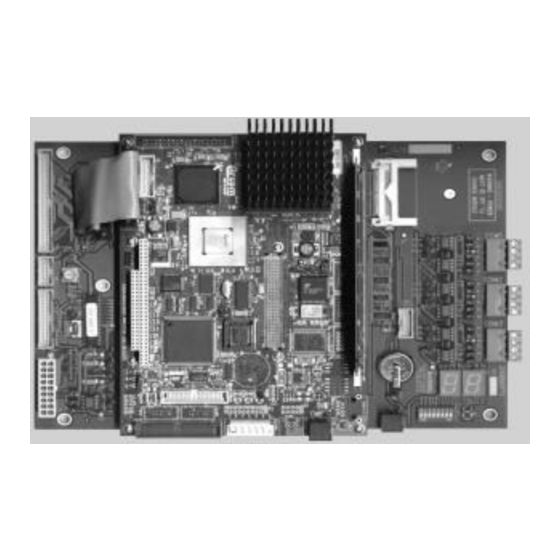
Page 8: Controller Board Pictorial
® S90-010 M FRICK QUANTUM™ COMPRESSOR CONTROL PANEL Page 8 MAINTENANCE QUANTUM™ 3 CONTROLLER BOARD PICTORIAL LK25 FLASH HEAT SINK MEMORY Display Cable SOCKET LK11 LK10 COM1 This assembly is shipped with LK24 LK11 set to position “B”. If a... -
Page 9: Flow Diagram - D.c. Voltage / Communications Harness
® FRICK QUANTUM™ COMPRESSOR CONTROL PANEL S90-010 M MAINTENANCE Page 9 QUANTUM™ 3 FLOW DIAGRAM - D.C. VOLTAGE / COMMUNICATIONS HARNESS Digital Power Board 1 Supply (Condor shown). Digital Board 2 Factory Connector Analog Board 2 DC Power - I/O Communications... -
Page 10: Quantum™ 4 Controller
® S90-010 M FRICK QUANTUM™ COMPRESSOR CONTROL PANEL Page 10 MAINTENANCE QUANTUM™ 4 CONTROLLER WHAT SHOULD OCCUR WHEN POWERING UP Check if an error message is displayed when THE PANEL booting. • Be sure to write down any error messages... -
Page 11: Controller Board Pictorial
® FRICK QUANTUM™ COMPRESSOR CONTROL PANEL S90-010 M MAINTENANCE Page 11 QUANTUM™ 4 CONTROLLER BOARD PICTORIAL Flash Card Socket (Located under board) Power PL11 COM-2 Cable COM-1 2 3 4 2 3 4 RS-422 PL12 RS-422 PL10 COM-2 +5VDC Cable... -
Page 12: Flow Diagram - D.c. Voltage / Communications Harness
® S90-010 M FRICK QUANTUM™ COMPRESSOR CONTROL PANEL Page 12 MAINTENANCE QUANTUM™ 4 FLOW DIAGRAM - D.C. VOLTAGE / COMMUNICATIONS HARNESS Digital Power Board 1 Supply (Condor shown). Digital Board 2 Factory Connector DC Power - Analog I/O Communications Board 2... -
Page 13: Digital Boards
® FRICK QUANTUM™ COMPRESSOR CONTROL PANEL S90-010 M MAINTENANCE Page 13 DIGITAL BOARDS The information that follows in this section can help locate Upon close examination of this harness, you will notice problems that can occur with Digital Input and Output that each of the connectors for both the Quantum™... -
Page 14: Active Led
® S90-010 M FRICK QUANTUM™ COMPRESSOR CONTROL PANEL Page 14 MAINTENANCE reads 4.98 Vdc, you can be assured that the voltage at the Never plug a 120 Volt Input module into a 240 Volt subsequent connections for the remaining boards will be system, and vice-versa. -
Page 15: Fuse Testing And Replacement
If the LED is not on when it should be and there QUANTUM™ DRAWINGS list drawing is no operating condition preventing it, contact number) for proper mounting location of the ® the Frick Service Department. board. If the LED is on when it should be, check for prevent possible noise problems from proper panel voltage on the DIO connector plug. -
Page 16: Digital I/O Board #1 Pictorial
® S90-010 M FRICK QUANTUM™ COMPRESSOR CONTROL PANEL Page 16 MAINTENANCE DIGITAL I/O BOARD #1 PICTORIAL INPUT MODULE OUTPUT MODULE POWER AMP794068-1 OUTPUT MODULE COMPR. START/RUN COMPR. AUX INPUT MODULE NEUTRAL OIL PUMP #1 OUTPUT MODULE START/RUN OIL PUMP #1 AUX... -
Page 17: Digital I/O Board #2 Pictorial
® FRICK QUANTUM™ COMPRESSOR CONTROL PANEL S90-010 M MAINTENANCE Page 17 DIGITAL I/O BOARD #2 PICTORIAL INPUT MODULE OUTPUT MODULE POWER AMP794068-1 OUTPUT MODULE READY TO RUN OPTIONAL REMOTE ENABLE OUTPUT MODULE OPTIONAL NEUTRAL INPUT MODULE REMOTE RUN/START/STOP OPTIONAL REMOTE LOAD... -
Page 18: Digital Board Settings
® S90-010 M FRICK QUANTUM™ COMPRESSOR CONTROL PANEL Page 18 MAINTENANCE DIGITAL BOARD SETTINGS COMMUNICATIONS SETTINGS DIPSWITCH SETTINGS 120 ohm long communications line termination. Board #1 out* No termination. Board #2 RS-422/485 transmit pull-up for long Board #3 communications lines. -
Page 19: Analog Boards
® FRICK QUANTUM™ COMPRESSOR CONTROL PANEL S90-010 M MAINTENANCE Page 19 ANALOG BOARDS The information that follows in this section can help locate remaining four connectors (16 pin) will plug into each of problems that can occur with Analog Input and Output the Digital and Analog Boards in the system (up to four circuit boards, and their interaction with the Quantum™... -
Page 20: Active Led
® S90-010 M FRICK QUANTUM™ COMPRESSOR CONTROL PANEL Page 20 MAINTENANCE Set the DVM to read “DC”, and set the proper range. The information and locations of jumpers. Also, see the section voltage reading must read a minimum of +4.98 Vdc. The entitled “Checking the Analog Inputs and Outputs”. -
Page 21: Replacing A Defective Analog Board
® FRICK QUANTUM™ COMPRESSOR CONTROL PANEL S90-010 M MAINTENANCE Page 21 to find a short to earth problem is to disconnect all the Check that all jumpers and components are sensor plugs and ohm out each plug screw terminal to setup properly (refer to the Analog Settings earth for open (infinite) impedance. -
Page 22: Analog Board #1
® S90-010 M FRICK QUANTUM™ COMPRESSOR CONTROL PANEL Page 22 MAINTENANCE ANALOG BOARD #1 AMP794068-1 SUCTION TEMP. DISCHARGE TEMP. OIL TEMP. SEPARATOR TEMP. LEAVING PROCESS TEMP. OIL PRESSURE PIN 8 = REMOTE CONTROL SETPOINT PIN 7 = GND PIN 6 = PROGRAMMABLE OUTPUT... -
Page 23: Analog Board #2
® FRICK QUANTUM™ COMPRESSOR CONTROL PANEL S90-010 M MAINTENANCE Page 23 ANALOG BOARD #2 AMP794068-1 FUTURE PID #1 FUTURE PID #2 FUTURE PID #3 ENTERING PROCESS TEMPERATURE TEMP. / PRESSURE MONITORING AUXILIARY ANALOG #1 TEMP. / PRESSURE MONITORING PIN 8 = CONDENSER OUTPUT... -
Page 24: Analog Board Settings
® S90-010 M FRICK QUANTUM™ COMPRESSOR CONTROL PANEL Page 24 MAINTENANCE ANALOG BOARD SETTINGS COMMUNICATIONS SETTINGS Input Channel #8 - Discharge Pressure out* 0-5 volt Input RS-422/485 receive pull-down for long 4-20 mA Input communications lines. ICTD Input out* No pull-down... -
Page 25: Analog Board #1 Output Jumpers
® FRICK QUANTUM™ COMPRESSOR CONTROL PANEL S90-010 M MAINTENANCE Page 25 ANALOG BOARD #1 OUTPUT JUMPERS Input Channel #7 - Temp.\Pressure Monitoring Aux. #3** 0-5 volt Input Output Channel #1 - PID / Programmable 1-2* 4-20 mA Input 0-20 mA Output... -
Page 26: Service Screen" - Analog Board Inputs And Outputs
® S90-010 M FRICK QUANTUM™ COMPRESSOR CONTROL PANEL Page 26 MAINTENANCE ANALOG BOARD #2 OUTPUT JUMPERS Output Channel #3 – Variable Speed Motor Drive 0-20 mA Output Output Channel #1 – PID / Programmable 2-3* 4-20 mA Output 0-20 mA Output... -
Page 27: Additional Service Related Screens
® FRICK QUANTUM™ COMPRESSOR CONTROL PANEL S90-010 M MAINTENANCE Page 27 ADDITIONAL SERVICE RELATED SCREENS “About” Screen The “About” screen shows the Analog and Digital boards messages that are associated with the sensors on that that have been detected. board lost board. -
Page 28: Scheduled Maintenance" Screen
® S90-010 M FRICK QUANTUM™ COMPRESSOR CONTROL PANEL Page 28 MAINTENANCE “Scheduled Maintenance” SCREEN This screen has been provided to help the service upon the Maintenance Schedule that is provided in the technician and can be accessed from the service screen. -
Page 29: Power Supply Identification, Adjusting And Replacing
® FRICK QUANTUM™ COMPRESSOR CONTROL PANEL S90-010 M MAINTENANCE Page 29 POWER SUPPLY IDENTIFICATION, ADJUSTMENT AND REPLACEMENT IDENTIFICATION ADJUSTMENT ® Frick Controls has used two power supplies in the All circuit boards within the Quantum™ control panel Quantum™ family. A Power One supply was originally require accurately adjusted DC voltages in order to used, primarily with the Quantum™... - Page 30 Since the Power ® when the screen is showing the normal "POST" style One is no longer available from Frick , an upgrade kit messages during a boot up. If the screen never appears can be ordered that will adapt the Condor supply to however (possibly due to a voltage problem), you will need the Power One mounting holes.
-
Page 31: Adjusting
® FRICK QUANTUM™ COMPRESSOR CONTROL PANEL S90-010 M MAINTENANCE Page 31 LK25 FLASH HEAT SINK MEMORY SOCKET LK11 LK10 COM1 Check voltages on the bottom and Check voltages on the bottom and top board as shown. The reading on top board as shown. The reading on... - Page 32 ® S90-010 M FRICK QUANTUM™ COMPRESSOR CONTROL PANEL Page 32 MAINTENANCE QUANTUM™ PANEL D.C. POWER SUPPLY LAYOUT (POWER-ONE) 120VAC Ground Neutral CAUTION Use only a screwdriver Pin 7 Pin 1 with an insulated shaft to perform adjustment (see NS-10-02 details).
- Page 33 ® FRICK QUANTUM™ COMPRESSOR CONTROL PANEL S90-010 M MAINTENANCE Page 33 QUANTUM™ PANEL DC POWER SUPPLY LAYOUT (CONDOR) +5VDC Adjustment (cut away view) CAUTION Use only a screwdriver with an insulated shaft to perform adjustment (see NS-10-02 details). 120VAC Ground...
-
Page 34: Identifying The Type Of Display
Verify the jumper (link) settings per the table near the white display mounting plate to the other, as shown the bottom of this page. below. If the distance is approximately 12-3/4", the display FRICK ASSEM NO. 640C0052G01 / L.G. PHILIPS DISPLAY NO. -
Page 35: Point-To-Point Field Wiring Diagram
MAINTENANCE Page 35 POINT-TO-POINT FIELD WIRING DIAGRAM 3 PHASE LINE NOTES: REFER TO MOTOR NAMEPLATE FOR CORRECT MOTOR CONNECTION. FRICK SUPPLIED COMBINATION SEPAERATE CONDUIT RUNS STARTER PACKAGE FOR CONTROL VOLTAGE Quantum™ WIRING AND MOTOR RWBII CONNECTION WIRING. CONSULT STARTER AND MOTOR WIRING DIAGRAMS... -
Page 36: Troubleshooting A Problem That Appears Unexplainable
“Lead” machine. 21. Make sure that you have a continuous ground ® • Check that you are using the Frick back to the power source. The ground connection recommended communications cable. See must be aluminum or copper. A conduit ground manual to match proper cable with type of will not work. -
Page 37: Troubleshooting Chart For Frick ® Quantum™ Control Panel
FRICK QUANTUM™ COMPRESSOR CONTROL PANEL S90-010 M MAINTENANCE Page 37 ® TROUBLESHOOTING CHART FOR FRICK QUANTUM™ CONTROL PANEL (REFER TO WIRING DIAGRAMS) SYMPTOM PROBABLE CAUSES and CORRECTIONS DISPLAY IS INOPERATIVE Check for power at the panel. See if any of the diagnostic lamps on the Main Board are blinking or any lights are blinking on the other boards. - Page 38 ® S90-010 M FRICK QUANTUM™ COMPRESSOR CONTROL PANEL Page 38 MAINTENANCE SYMPTOM PROBABLE CAUSES and CORRECTIONS OIL HEATERS DO NOT OPERATE The oil heaters should operate only when the compressor is NOT running and the oil separator temperature is not greater than or equal to the “Oil Heater Off Above”...
- Page 39 ® FRICK QUANTUM™ COMPRESSOR CONTROL PANEL S90-010 M MAINTENANCE Page 39 SYMPTOM PROBABLE CAUSES and CORRECTIONS SLIDE STOP DOES NOT INCREASE Verify that the Slide Stop is in the AUTO mode and that the VI Ratio is calling and/or DECREASE* Some Compressor for a VI increase or decrease.
-
Page 40: Compressor Model Differences
The current transformer is used to convert the AC motor amps to a DC voltage UNLOAD) OCCURS AT HIGH MOTOR signal for the microprocessor. If the %FLA reading from the Operating display ® AMPS is incorrect, contact the Frick Service Department. MOTOR LOAD CONTROL(FORCED... -
Page 41: Setpoint Data Sheets
® FRICK QUANTUM™ COMPRESSOR CONTROL PANEL S90-010 M MAINTENANCE Page 41 SETPOINT DATA SHEETS In most cases, updating software on the Quantum™ panel will require clearing the current setpoints and data stored in the nonvolatile memory on the main board. It is suggested that the operator first record all control setpoints prior to performing program chip upgrades. - Page 42 ® S90-010 M FRICK QUANTUM™ COMPRESSOR CONTROL PANEL Page 42 MAINTENANCE FACTORY SETPOINTS Volume Ratio (Vi) Range Proportional High Dead Band Band Oil Pump (Low Oil Pressure): Running Running Alarm Shutdown Alarm Alarm Shutdown Shutdown Delay (secs.) delay (secs.) (Differential)
-
Page 43: Panel Setup
® FRICK QUANTUM™ COMPRESSOR CONTROL PANEL S90-010 M MAINTENANCE Page 43 Balance Piston Setup: Output on Output off Ignore Delay Fail Delay Enable Disable slide valve % slide valve % (0 - 10) min. (0 - 10) min. default 70%... - Page 44 ® S90-010 M FRICK QUANTUM™ COMPRESSOR CONTROL PANEL Page 44 MAINTENANCE Capacity Control Selection: Select capacity control (2 maximum) Suction pressure ______ Process temperature ______ Discharge pressure (air compressor mode) ______ User Selectable mode ______ User Selectable Mode: Action Enable...
- Page 45 ® FRICK QUANTUM™ COMPRESSOR CONTROL PANEL S90-010 M MAINTENANCE Page 45 Auxiliary Analog Temperatures and Pressures: Enabled Disabled Entering Process Temperature: Enabled Disabled Slide Valve Position Control: Remote Control Setpoint: Enabled Disabled Enabled Disabled Permissive Start: Disable Always Active Starting...
-
Page 46: Calibration
® S90-010 M FRICK QUANTUM™ COMPRESSOR CONTROL PANEL Page 46 MAINTENANCE CALIBRATION (while in factory setup) Pressure Transducers and Temperature Sensors: Transducer Transducer Sensor Type Pressure High End Low End 1 - 5 Vdc, 0 - 5 Vdc Transducer (default is... - Page 47 ® FRICK QUANTUM™ COMPRESSOR CONTROL PANEL S90-010 M MAINTENANCE Page 47 Sensor High End Sensor Low End Sensor Type ICTD, Auxiliary Text Units (default is (default is 1 - 5 Vdc, 0 - 5 Vdc Analog 485.3 psig) 30.0 in hg.)
-
Page 48: Capacity Control Setpoints
® S90-010 M FRICK QUANTUM™ COMPRESSOR CONTROL PANEL Page 48 MAINTENANCE CAPACITY CONTROL SETPOINTS SUCTION PRESSURE CONTROL MODE #1 setting default range Capacity Control Setpoint ______ 20 psig 30" - 135 psig Upper Proportional Band ______ 4 psig 0 - 20 psig... -
Page 49: Process Temp Control Mode #1
® FRICK QUANTUM™ COMPRESSOR CONTROL PANEL S90-010 M MAINTENANCE Page 49 PROCESS TEMP CONTROL MODE #1 setting default range Capacity Control Setpoint ______ 40°F -238 - 302°F Upper Proportional Band ______ 4°F 0 - 20 °F Upper Dead Band ______ 1°F... -
Page 50: Discharge Pressure Control Mode #1
® S90-010 M FRICK QUANTUM™ COMPRESSOR CONTROL PANEL Page 50 MAINTENANCE DISCHARGE PRESSURE CONTROL MODE #1 setting default range Capacity Control Setpoint ______ 150 psig 0 - 350** psig Upper Proportional Band ______ 5 psig 0 - 20 psig Upper Dead Band... -
Page 51: User Selectable Control Mode #1
® FRICK QUANTUM™ COMPRESSOR CONTROL PANEL S90-010 M MAINTENANCE Page 51 USER SELECTABLE CONTROL MODE #1 setting default range Capacity Control Setpoint ______ 150°F 32 - 482°F Upper Proportional Band ______ 4°F 0 - 20°F Upper Dead Band ______ 1°F 0 - 10°F... -
Page 52: Compressor Safeties
® S90-010 M FRICK QUANTUM™ COMPRESSOR CONTROL PANEL Page 52 MAINTENANCE COMPRESSOR SAFETIES DISCHARGE SAFETIES setting default range High Discharge Temp Stop Load ______ 180°F 0 - 249.8°F High Discharge Temp Force Unload ______ 190°F 0 - 249.8°F High Discharge Temp Alarm ______ 200°F... -
Page 53: Motor Control
® FRICK QUANTUM™ COMPRESSOR CONTROL PANEL S90-010 M MAINTENANCE Page 53 OIL LEVEL DELAY setting default range Oil Level Delay ______ 300 sec. 0 - 600 sec. MOTOR CONTROL setting default range Motor Amps ______ 0 - 3000 Volts ______... -
Page 54: Ram Dbs Motor Starter
® S90-010 M FRICK QUANTUM™ COMPRESSOR CONTROL PANEL Page 54 MAINTENANCE RAM DBS MOTOR STARTER setting default range Locked Rotor Current ______ 0.0% FLA 300 - 800% FLA Stall Time ______ 0 sec. 0 - 60 sec. Jam Current Level ______ 0.0% FLA... -
Page 55: Slide Valve Setpoints
® FRICK QUANTUM™ COMPRESSOR CONTROL PANEL S90-010 M MAINTENANCE Page 55 SLIDE VALVE SETPOINTS setting default range Highest Slide Valve Position To Allow Starting Of The Compressor: ______ 5 - 100% Starting Period before Slide Valve will load ______ 0 sec. -
Page 56: Pid Setup
® S90-010 M FRICK QUANTUM™ COMPRESSOR CONTROL PANEL Page 56 MAINTENANCE PID Setup Ch. 1 Ch. 2 Ch. 3 Ch. 4 Range Default Forward Action Reverse Control ______ ______ ______ ______ Setpoint Dependant on Input selected Dependant on Input selected... -
Page 57: Auxiliary Inputs Setup
® FRICK QUANTUM™ COMPRESSOR CONTROL PANEL S90-010 M MAINTENANCE Page 57 AUXILIARY INPUTS SETUP Alarm Alarm Shutdown Shutdown Delay Auxiliary Disabled Text Check Check Check Check (0-99) sec. Always * Running Always Running (Default 5) Auxiliary 1 Auxiliary 2 Auxiliary 3... -
Page 58: Auxiliary Analogs
® S90-010 M FRICK QUANTUM™ COMPRESSOR CONTROL PANEL Page 58 MAINTENANCE AUXILIARY ANALOGS Auxiliary Disabled Text Check Always Check Running Auxiliary 1 Auxiliary 2 Auxiliary 3 Auxiliary 4 Auxiliary 5 Auxiliary 6 Auxiliary 7 Auxiliary 8 Auxiliary 9 Auxiliary 10 *... -
Page 59: Scheduled Maintenance
® FRICK QUANTUM™ COMPRESSOR CONTROL PANEL S90-010 M MAINTENANCE Page 59 SCHEDULED MAINTENANCE SETPOINTS Maintenance Required Service Every Next Scheduled At Default Name User Defined Name Oil Analysis Change Filters Clean Oil Strainers Clean Lqd Strainers Change Coelescers Clean Suction Screen... -
Page 60: Quantum™ Drawings
® S90-010 M FRICK QUANTUM™ COMPRESSOR CONTROL PANEL Page 60 MAINTENANCE QUANTUM™ DRAWINGS This table lists the numbers for the drawings that appear on the following pages. The drawings shown here are the latest revision as of the printing of this manual. These drawings appear here for reference purposes only, and are subject to change without notice. -
Page 61: Control Center Assembliy Rwf / Rxf
® FRICK QUANTUM™ COMPRESSOR CONTROL PANEL S90-010 M MAINTENANCE Page 61 RWF / RXF (58 - 101) CONTROL CENTER ASSEMBLY (Sheet 1 of 4) DANGER Do not drill through top pf panel. This drawing appears here for reference purposes only, and is subject to change without notice. When installing, or servicing... - Page 62 ® S90-010 M FRICK QUANTUM™ COMPRESSOR CONTROL PANEL Page 62 MAINTENANCE RWF / RXF (58 - 101) CONTROL CENTER ASSEMBLY (Sheet 2 of 4) This drawing appears here for reference purposes only, and is subject to change without notice. When installing, or servicing...
- Page 63 ® FRICK QUANTUM™ COMPRESSOR CONTROL PANEL S90-010 M MAINTENANCE Page 63 RWF / RXF (58 - 101) CONTROL CENTER ASSEMBLY (Sheet 3 of 4) This drawing appears here for reference purposes only, and is subject to change without notice. When installing, or servicing...
- Page 64 ® S90-010 M FRICK QUANTUM™ COMPRESSOR CONTROL PANEL Page 64 MAINTENANCE RWF / RXF (58 - 101) CONTROL CENTER ASSEMBLY (Sheet 4 of 4) This drawing appears here for reference purposes only, and is subject to change without notice. When installing, or servicing...
-
Page 65: Rxf (12-50)
® FRICK QUANTUM™ COMPRESSOR CONTROL PANEL S90-010 M MAINTENANCE Page 65 RXF (12-50) CONTROL CENTER ASSEMBLY (Sheet 1 of 2) This drawing appears here for reference purposes only, and is subject to change without notice. When installing, or servicing equipment, always refer to the actual drawings that are included with the control panel for the latest information. - Page 66 ® S90-010 M FRICK QUANTUM™ COMPRESSOR CONTROL PANEL Page 66 MAINTENANCE RXF (12-50) CONTROL CENTER ASSEMBLY (Sheet 2 of 2) This drawing appears here for reference purposes only, and is subject to change without notice. When installing, or servicing equipment, always refer to the actual drawings that are included with the control panel for the latest information.
-
Page 67: Rdb
® FRICK QUANTUM™ COMPRESSOR CONTROL PANEL S90-010 M MAINTENANCE Page 67 RDB CONTROL CENTER ASSEMBLY (Sheet 1 of 4) This drawing appears here for reference purposes only, and is subject to change without notice. When installing, or servicing equipment, always refer to the actual drawings that are included with the control panel for the latest information. - Page 68 ® S90-010 M FRICK QUANTUM™ COMPRESSOR CONTROL PANEL Page 68 MAINTENANCE RDB CONTROL CENTER ASSEMBLY (Sheet 2 of 4) This drawing appears here for reference purposes only, and is subject to change without notice. When installing, or servicing equipment, always refer to the actual drawings that are included with the control panel for the latest information.
- Page 69 ® FRICK QUANTUM™ COMPRESSOR CONTROL PANEL S90-010 M MAINTENANCE Page 69 RDB CONTROL CENTER ASSEMBLY (Sheet 3 of 4) This drawing appears here for reference purposes only, and is subject to change without notice. When installing, or servicing equipment, always refer to the actual drawings that are included with the control panel for the latest information.
- Page 70 ® S90-010 M FRICK QUANTUM™ COMPRESSOR CONTROL PANEL Page 70 MAINTENANCE RDB CONTROL CENTER ASSEMBLY (Sheet 4 of 4) This drawing appears here for reference purposes only, and is subject to change without notice. When installing, or servicing equipment, always refer to the actual drawings that are included with the control panel for the latest information.
-
Page 71: Rwbii
® FRICK QUANTUM™ COMPRESSOR CONTROL PANEL S90-010 M MAINTENANCE Page 71 RWBII CONTROL CENTER ASSEMBLY (Sheet 1 of 4) This drawing appears here for reference purposes only, and is subject to change without notice. When installing, or servicing equipment, always refer to the actual drawings that are included with the control panel for the latest information. - Page 72 ® S90-010 M FRICK QUANTUM™ COMPRESSOR CONTROL PANEL Page 72 MAINTENANCE RWBII CONTROL CENTER ASSEMBLY (Sheet 2 of 4) This drawing appears here for reference purposes only, and is subject to change without notice. When installing, or servicing equipment, always refer to the actual drawings that are included with the control panel for the latest information.
- Page 73 ® FRICK QUANTUM™ COMPRESSOR CONTROL PANEL S90-010 M MAINTENANCE Page 73 RWBII CONTROL CENTER ASSEMBLY (Sheet 3 of 4) This drawing appears here for reference purposes only, and is subject to change without notice. When installing, or servicing equipment, always refer to the actual drawings that are included with the control panel for the latest information.
- Page 74 ® S90-010 M FRICK QUANTUM™ COMPRESSOR CONTROL PANEL Page 74 MAINTENANCE RWBII CONTROL CENTER ASSEMBLY (Sheet 4 of 4) This drawing appears here for reference purposes only, and is subject to change without notice. When installing, or servicing equipment, always refer to the actual drawings that are included with the control panel for the latest information.
-
Page 75: Retrofit Rxb / Rxf (58-101)
® FRICK QUANTUM™ COMPRESSOR CONTROL PANEL S90-010 M MAINTENANCE Page 75 RETROFIT RXB / RXF (58-101) CONTROL CENTER ASSEMBLY (Sheet 1 of 4) This drawing appears here for reference purposes only, and is subject to change without notice. When installing, or servicing... - Page 76 ® S90-010 M FRICK QUANTUM™ COMPRESSOR CONTROL PANEL Page 76 MAINTENANCE RETROFIT RXB / RXF (58-101) CONTROL CENTER ASSEMBLY (Sheet 2 of 4) This drawing appears here for reference purposes only, and is subject to change without notice. When installing, or servicing...
- Page 77 ® FRICK QUANTUM™ COMPRESSOR CONTROL PANEL S90-010 M MAINTENANCE Page 77 RETROFIT RXB / RXF (58-101) CONTROL CENTER ASSEMBLY (Sheet 3 of 4) This drawing appears here for reference purposes only, and is subject to change without notice. When installing, or servicing...
- Page 78 ® S90-010 M FRICK QUANTUM™ COMPRESSOR CONTROL PANEL Page 78 MAINTENANCE RETROFIT RXB / RXF (58-101) CONTROL CENTER ASSEMBLY (Sheet 4 of 4) This drawing appears here for reference purposes only, and is subject to change without notice. When installing, or servicing...
-
Page 79: Rwf (58-101)
® FRICK QUANTUM™ COMPRESSOR CONTROL PANEL S90-010 M MAINTENANCE Page 79 WIRING DIAGRAM – RWF (Sheet 1 of 5) This drawing appears here for reference purposes only, and is subject to change without notice. When installing, or servicing equipment, always refer to the actual drawings that are included with the control panel for the latest information. - Page 80 ® S90-010 M FRICK QUANTUM™ COMPRESSOR CONTROL PANEL Page 80 MAINTENANCE WIRING DIAGRAM - RWF (Sheet 2 of 5) This drawing appears here for reference purposes only, and is subject to change without notice. When installing, or servicing equipment, always refer to the actual drawings that are included with the control panel for the latest information.
- Page 81 ® FRICK QUANTUM™ COMPRESSOR CONTROL PANEL S90-010 M MAINTENANCE Page 81 WIRING DIAGRAM - RWF (Sheet 3 of 5) This drawing appears here for reference purposes only, and is subject to change without notice. When installing, or servicing equipment, always refer to the actual drawings that are included with the control panel for the latest information.
- Page 82 ® S90-010 M FRICK QUANTUM™ COMPRESSOR CONTROL PANEL Page 82 MAINTENANCE WIRING DIAGRAM - RWF (Sheet 4 of 5) This drawing appears here for reference purposes only, and is subject to change without notice. When installing, or servicing equipment, always refer to the actual drawings that are included with the control panel for the latest information.
- Page 83 ® FRICK QUANTUM™ COMPRESSOR CONTROL PANEL S90-010 M MAINTENANCE Page 83 WIRING DIAGRAM - RWF (Sheet 5 of 5) This drawing appears here for reference purposes only, and is subject to change without notice. When installing, or servicing equipment, always refer to the actual drawings that are included with the control panel for the latest information.
-
Page 84: Rwb Ii
® S90-010 M FRICK QUANTUM™ COMPRESSOR CONTROL PANEL Page 84 MAINTENANCE WIRING DIAGRAM – RWB II (Sheet 1 of 5) This drawing appears here for reference purposes only, and is subject to change without notice. When installing, or servicing equipment, always refer to the actual drawings that are included with the control panel for the latest information. - Page 85 ® FRICK QUANTUM™ COMPRESSOR CONTROL PANEL S90-010 M MAINTENANCE Page 85 WIRING DIAGRAM – RWB II (Sheet 2 of 5) This drawing appears here for reference purposes only, and is subject to change without notice. When installing, or servicing equipment, always refer to the actual drawings that are included with the control panel for the latest information.
- Page 86 ® S90-010 M FRICK QUANTUM™ COMPRESSOR CONTROL PANEL Page 86 MAINTENANCE WIRING DIAGRAM – RWB II (Sheet 3 of 5) This drawing appears here for reference purposes only, and is subject to change without notice. When installing, or servicing equipment, always refer to the actual drawings that are included with the control panel for the latest information.
- Page 87 ® FRICK QUANTUM™ COMPRESSOR CONTROL PANEL S90-010 M MAINTENANCE Page 87 WIRING DIAGRAM – RWB II (Sheet 4 of 5) This drawing appears here for reference purposes only, and is subject to change without notice. When installing, or servicing equipment, always refer to the actual drawings that are included with the control panel for the latest information.
- Page 88 ® S90-010 M FRICK QUANTUM™ COMPRESSOR CONTROL PANEL Page 88 MAINTENANCE WIRING DIAGRAM – RWB II (Sheet 5 of 5) This drawing appears here for reference purposes only, and is subject to change without notice. When installing, or servicing equipment, always refer to the actual drawings that are included with the control panel for the latest information.
-
Page 89: Rxf (12-50)
® FRICK QUANTUM™ COMPRESSOR CONTROL PANEL S90-010 M MAINTENANCE Page 89 WIRING DIAGRAM – RXF (12-50) - (Sheet 1 of 5) This drawing appears here for reference purposes only, and is subject to change without notice. When installing, or servicing... - Page 90 ® S90-010 M FRICK QUANTUM™ COMPRESSOR CONTROL PANEL Page 90 MAINTENANCE WIRING DIAGRAM – RXF (12-50) - (Sheet 2 of 5) This drawing appears here for reference purposes only, and is subject to change without notice. When installing, or servicing...
- Page 91 ® FRICK QUANTUM™ COMPRESSOR CONTROL PANEL S90-010 M MAINTENANCE Page 91 WIRING DIAGRAM – RXF (12-50) - (Sheet 3 of 5) This drawing appears here for reference purposes only, and is subject to change without notice. When installing, or servicing...
- Page 92 ® S90-010 M FRICK QUANTUM™ COMPRESSOR CONTROL PANEL Page 92 MAINTENANCE WIRING DIAGRAM – RXF (12-50) - (Sheet 4 of 5) This drawing appears here for reference purposes only, and is subject to change without notice. When installing, or servicing...
- Page 93 ® FRICK QUANTUM™ COMPRESSOR CONTROL PANEL S90-010 M MAINTENANCE Page 93 WIRING DIAGRAM – RXF (12-50) - (Sheet 5 of 5) This drawing appears here for reference purposes only, and is subject to change without notice. When installing, or servicing...
-
Page 94: Rxf (58-101)
® S90-010 M FRICK QUANTUM™ COMPRESSOR CONTROL PANEL Page 94 MAINTENANCE WIRING DIAGRAM – RXF (58-101) (Sheet 1 of 5) This drawing appears here for reference purposes only, and is subject to change without notice. When installing, or servicing equipment, always refer to the actual drawings that are included with the control panel for the latest information. - Page 95 ® FRICK QUANTUM™ COMPRESSOR CONTROL PANEL S90-010 M MAINTENANCE Page 95 WIRING DIAGRAM – RXF (58-101) (Sheet 2 of 4) This drawing appears here for reference purposes only, and is subject to change without notice. When installing, or servicing equipment, always refer to the actual drawings that are included with the control panel for the latest information.
- Page 96 ® S90-010 M FRICK QUANTUM™ COMPRESSOR CONTROL PANEL Page 96 MAINTENANCE WIRING DIAGRAM – RXF (58-101) (Sheet 3 of 5) This drawing appears here for reference purposes only, and is subject to change without notice. When installing, or servicing equipment, always refer to the actual drawings that are included with the control panel for the latest information.
- Page 97 ® FRICK QUANTUM™ COMPRESSOR CONTROL PANEL S90-010 M MAINTENANCE Page 97 WIRING DIAGRAM – RXF (58-101) (Sheet 4 of 5) This drawing appears here for reference purposes only, and is subject to change without notice. When installing, or servicing equipment, always refer to the actual drawings that are included with the control panel for the latest information.
- Page 98 ® S90-010 M FRICK QUANTUM™ COMPRESSOR CONTROL PANEL Page 98 MAINTENANCE WIRING DIAGRAM – RXF (58-101) (Sheet 5 of 5) This drawing appears here for reference purposes only, and is subject to change without notice. When installing, or servicing equipment, always refer to the actual drawings that are included with the control panel for the latest information.
-
Page 99: Rdb
® FRICK QUANTUM™ COMPRESSOR CONTROL PANEL S90-010 M MAINTENANCE Page 99 WIRING DIAGRAM – RDB (Sheet 1 of 5) This drawing appears here for reference purposes only, and is subject to change without notice. When installing, or servicing equipment, always refer to the actual drawings that are included with the control panel for the latest information. - Page 100 ® S90-010 M FRICK QUANTUM™ COMPRESSOR CONTROL PANEL Page 100 MAINTENANCE WIRING DIAGRAM – RDB (Sheet 2 of 5) This drawing appears here for reference purposes only, and is subject to change without notice. When installing, or servicing equipment, always refer to the actual drawings that are included with the control panel for the latest information.
- Page 101 ® FRICK QUANTUM™ COMPRESSOR CONTROL PANEL S90-010 M MAINTENANCE Page 101 WIRING DIAGRAM – RDB (Sheet 3 of 5) This drawing appears here for reference purposes only, and is subject to change without notice. When installing, or servicing equipment, always refer to the actual drawings that are included with the control panel for the latest information.
- Page 102 ® S90-010 M FRICK QUANTUM™ COMPRESSOR CONTROL PANEL Page 102 MAINTENANCE WIRING DIAGRAM – RDB (Sheet 4 of 5) This drawing appears here for reference purposes only, and is subject to change without notice. When installing, or servicing equipment, always refer to the actual drawings that are included with the control panel for the latest information.
- Page 103 ® FRICK QUANTUM™ COMPRESSOR CONTROL PANEL S90-010 M MAINTENANCE Page 103 WIRING DIAGRAM – RDB (Sheet 5 of 5) This drawing appears here for reference purposes only, and is subject to change without notice. When installing, or servicing equipment, always refer to the actual drawings that are included with the control panel for the latest information.
-
Page 104: Standard Digital I/O Board 2
® S90-010 M FRICK QUANTUM™ COMPRESSOR CONTROL PANEL Page 104 MAINTENANCE WIRING DIAGRAM - STANDARD DIGITAL I/O BOARD 2 (Sheet 1 of 3) This drawing appears here for reference purposes only, and is subject to change without notice. When installing, or servicing... - Page 105 ® FRICK QUANTUM™ COMPRESSOR CONTROL PANEL S90-010 M MAINTENANCE Page 105 WIRING DIAGRAM - STANDARD DIGITAL I/O BOARD 2 (Sheet 2 of 3) This drawing appears here for reference purposes only, and is subject to change without notice. When installing, or servicing...
- Page 106 ® S90-010 M FRICK QUANTUM™ COMPRESSOR CONTROL PANEL Page 106 MAINTENANCE WIRING DIAGRAM - STANDARD DIGITAL I/O BOARD 2 (Sheet 3 of 3) This drawing appears here for reference purposes only, and is subject to change without notice. When installing, or servicing...
-
Page 107: Rxf (12-50) Digital I/O Board 2
® FRICK QUANTUM™ COMPRESSOR CONTROL PANEL S90-010 M MAINTENANCE Page 107 WIRING DIAGRAM - RXF (12-50) DIGITAL I/O BOARD 2 (Sheet 1 of 3) This drawing appears here for reference purposes only, and is subject to change without notice. When installing, or servicing... - Page 108 ® S90-010 M FRICK QUANTUM™ COMPRESSOR CONTROL PANEL Page 108 MAINTENANCE WIRING DIAGRAM - RXF (12-50) DIGITAL I/O BOARD 2 (Sheet 2 of 3) This drawing appears here for reference purposes only, and is subject to change without notice. When installing, or servicing...
- Page 109 ® FRICK QUANTUM™ COMPRESSOR CONTROL PANEL S90-010 M MAINTENANCE Page 109 WIRING DIAGRAM - RXF (12-50) DIGITAL I/O BOARD 2 (Sheet 3 of 3) This drawing appears here for reference purposes only, and is subject to change without notice. When installing, or servicing...
-
Page 110: Standard Analog I/O Board 2
® S90-010 M FRICK QUANTUM™ COMPRESSOR CONTROL PANEL Page 110 MAINTENANCE WIRING DIAGRAM STANDARD ANALOG I/O BOARD 2 (Sheet 1 of 3) This drawing appears here for reference purposes only, and is subject to change without notice. When installing, or servicing... - Page 111 ® FRICK QUANTUM™ COMPRESSOR CONTROL PANEL S90-010 M MAINTENANCE Page 111 WIRING DIAGRAM STANDARD ANALOG I/O BOARD 2 (Sheet 2 of 3) This drawing appears here for reference purposes only, and is subject to change without notice. When installing, or servicing...
- Page 112 ® S90-010 M FRICK QUANTUM™ COMPRESSOR CONTROL PANEL Page 112 MAINTENANCE WIRING DIAGRAM STANDARD ANALOG I/O BOARD 2 (Sheet 3 of 3) This drawing appears here for reference purposes only, and is subject to change without notice. When installing, or servicing...
-
Page 113: Quantum™ I/O & D.c. Power Harness
® FRICK QUANTUM™ COMPRESSOR CONTROL PANEL S90-010 M MAINTENANCE Page 113 QUANTUM™ I/O & D.C. POWER HARNESS This drawing appears here for reference purposes only, and is subject to change without notice. When installing, or servicing equipment, always refer to the actual drawings that are included with the control panel for the latest information. -
Page 114: Communications Wiring Diagrams
® S90-010 M FRICK QUANTUM™ COMPRESSOR CONTROL PANEL Page 114 MAINTENANCE COMMUNICATIONS WIRING DIAGRAMS TO CUSTOMER REMOTE COMPUTER/DCS RS-485 COMMUNICATIONS QUANTUM™ 1 OR 2 QUANTUM™ 3 OR 4 QUANTUM™ 3 OR 4 QUANTUM™ 3 OR 4 To Customer COM-2 (P12) -
Page 115: Pressure Transducer Conversion Data
® FRICK QUANTUM™ COMPRESSOR CONTROL PANEL S90-010 M MAINTENANCE Page 115 PRESSURE TRANSDUCER CONVERSION DATA (Data Instruments Model SA) 100 psi 200 psi 300 psi 500 psi Sensor Range - psig* Range - psig* Range - psig* Range - psig*... -
Page 116: Recommended Spare Parts
333Q0001326 Fuse, 5 amp, 250 V (I/O board) Analog Boards 640C0026G01 Analog Borad #1 640C0026G02 Analog Board #2 Keypads ® 640D0060H01 Keypad/overlay Frick ’s 640D0066H01 Keypad/overlay Gram’s 640B0031H01 Keypad cable Circuit Breakers 649A0883H10 10 Amp circuit breaker 649A0883H16 16 Amp circuit breaker Quantum™... -
Page 117: Index
® FRICK QUANTUM™ COMPRESSOR CONTROL PANEL S90-010 M MAINTENANCE Page 117 INDEX Dipswitch............13, 18, 19, 24 Display...... 5, 6, 7, 8, 10, 11, 34, 37, 40, 42, 116 About Screen ..............27 DVM.…...............13, 19, 36 AC…..…................10 Active LED ..............7, 10 Analog EPROM.. - Page 118 ® S90-010 M FRICK QUANTUM™ COMPRESSOR CONTROL PANEL Page 118 MAINTENANCE Main Board ..............5, 37 Range……..13, 14, 19, 20, 27, 29, 42, 43, 45, 48, 49, Memory............5, 7, 10, 41 50, 51, 52, 53, 54, 55, 56, 58 Menu.…................
Need help?
Do you have a question about the QUANTUM 3 and is the answer not in the manual?
Questions and answers