Frick QUANTUM LX Installation Operation & Maintenance

Frick QUANTUM LX Installation Operation & Maintenance

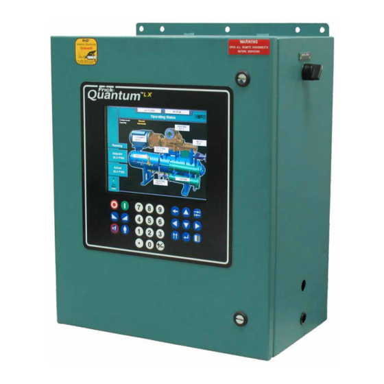
System interface panel
Hide thumbs Also See for QUANTUM LX:

Advertisement

INSTALLATION-OPERATION-MAINTENANCE
FRICK
®
SYSTEM INTERFACE PANEL
Form 090.030-IOM (OCTOBER 2013)
INSTALLATION-OPERATION-MAINTENANCE
File:
Replaces:
Dist:
QUANTUM™ LX/HD
Version 2.0x
SERVICE MANUAL - Section 90
090.030-O (MAR 12)
3, 3a, 3b, 3c

Advertisement

Table of Contents
loading
Need help?

Need help?

Do you have a question about the QUANTUM LX and is the answer not in the manual?

Questions and answers

Subscribe to Our Youtube Channel

Summary of Contents for Frick QUANTUM LX

  • Page 1 Form 090.030-IOM (OCTOBER 2013) INSTALLATION-OPERATION-MAINTENANCE File: SERVICE MANUAL - Section 90 Replaces: 090.030-O (MAR 12) Dist: 3, 3a, 3b, 3c INSTALLATION-OPERATION-MAINTENANCE FRICK QUANTUM™ LX/HD ® SYSTEM INTERFACE PANEL Version 2.0x...
  • Page 2: Table Of Contents

    Any modifi cation to the standard default settings may have a severe negative impact on the operation and performance of the equipment. Any modifi cation to these control settings is the sole responsibility of the user/owner and Frick disclaims any liability for the consequences of these modifi...
  • Page 3: Overview Of A Typical System

    The primary function of the System Interface Panel (SIP) is to allow a common access point for networking multiple Frick Quantum™ LX and/or HD panels together, for the purpose of monitoring and control. This System Interface Panel (SIP) has been designed to allow an operator to effi...
  • Page 4: Basic Sip Connections

    INSTALLATION-OPERATION-MAINTENANCE Page 4 BASIC SIP CONNECTIONS The Frick SIP may be connected directly to a single Quan- For multiple Panels - Each cable should be routed back tum™ LX or HD panel for a minimum system confi guration, or from the Quantum™ LX or HD panel to a common area, it may be connected to an existing Ethernet network.
  • Page 5: Locating The Ethernet Connections

    QUANTUM™ LX/HD SYSTEM INTERFACE PANEL 090.030-IOM (OCT 13) INSTALLATION-OPERATION-MAINTENANCE Page 5 LOCATING THE ETHERNET CONNECTIONS For a Quantum™ LX or HD with a Q5 processor: NOTE: All Quantum™ HD panels utilize the Q5 processor board, however, the Quantum™ LX panel may have either a Q4 The Ethernet connector for the Q5 panel can be found by or Q5 controller.
  • Page 6: Calibrating The Sip

    QUANTUM™ LX/HD SYSTEM INTERFACE PANEL 090.030-IOM (OCT 13) INSTALLATION-OPERATION-MAINTENANCE Page 6 CALIBRATING THE SIP Touch Screen Calibration Pressing anywhere on the screen within the fi ve second countdown will cause the screen to show As the SIP comes from the factory, calibration has already the following image in the upper left corner: been performed, and as such, should not be needed.
  • Page 7: Sip Page Introduction

    Using the List page as an example: Header Page List Header - The area at the top of all pages shows the Frick • Manage Tags - Selecting this will allow custom nam- logo, the name “System Interface Panel”, the IP Address, ing of panel groups.
  • Page 8: List Page

    QUANTUM™ LX/HD SYSTEM INTERFACE PANEL 090.030-IOM (OCT 13) INSTALLATION-OPERATION-MAINTENANCE Page 8 LIST Page Work Group Tag Names The List page can be thought of as a Home page. It is from here that an overall picture of the entire system can be viewed. The List Page displays all the units recognized and accessible through the System Interface Panel by accessing the Work Group Tag Names.
  • Page 9: Manage Panels Page

    QUANTUM™ LX/HD SYSTEM INTERFACE PANEL 090.030-IOM (OCT 13) INSTALLATION-OPERATION-MAINTENANCE Page 9 MANAGE PANELS Page This page provides a detailed listing of all panels that have Use this keyboard to enter a unique name that helps been confi gured for this system. Panels that are confi gured to describe the location or function that applies to the here, will be displayed on the List page.
  • Page 10 QUANTUM™ LX/HD SYSTEM INTERFACE PANEL 090.030-IOM (OCT 13) INSTALLATION-OPERATION-MAINTENANCE Page 10 Once the above entries have been made, select the [Submit] Actions - button to update the Manage Panels page. The [Cancel] button will void all changes and return you to the Add Pages screen. Selecting this ICON will cause the Once a panel or panels have been added, they will now appear Modify Panel page to appear.
  • Page 11: Manage Tags Page

    QUANTUM™ LX/HD SYSTEM INTERFACE PANEL 090.030-IOM (OCT 13) INSTALLATION-OPERATION-MAINTENANCE Page 11 MANAGE TAGS Page DESCRIPTION: A Tag is simply a name that you may assign for Actions - a Work Group. Each Work group can contain one or multiple panels. Work Groups do not need to be created, but in facili- Selecting this ICON will cause the ties where multiple panels exist it can be a benefi...
  • Page 12: About Page

    QUANTUM™ LX/HD SYSTEM INTERFACE PANEL 090.030-IOM (OCT 13) INSTALLATION-OPERATION-MAINTENANCE Page 12 ABOUT Page This page provides information about the panel. These pieces of information will be necessary if factory assis- tance is ever required.
  • Page 13: Configuration Page

    QUANTUM™ LX/HD SYSTEM INTERFACE PANEL 090.030-IOM (OCT 13) INSTALLATION-OPERATION-MAINTENANCE Page 13 CONFIGURATION Page NOTE 1: The proper setup of this screen is critical, and is work together. Applying the subnet mask to an IP ad- best left to the network administrator to perform. dress splits the address into two parts, an extended network address and a host address.
  • Page 14: Alarm Page

    QUANTUM™ LX/HD SYSTEM INTERFACE PANEL 090.030-IOM (OCT 13) INSTALLATION-OPERATION-MAINTENANCE Page 14 ALARM page The Alarm Page can be accessed from any page by simply at the beginning of each row. Selecting this PLUS symbol will selecting the red button in the upper right corner. If no alarms show the actual alarm message that is active for that panel are present within the system, that Alarms button will show (if any alarms are present).
  • Page 15: Sip Maintenance

    Q5 CONTROLLER BOARD INTRODUCTION WHAT IF THE SIP LIST PAGE IS NOT SHOWN Frick® Controls has released the latest version of the If the List page is not shown, check the following items: Quantum ™ Control System. The micro-processor is the brains of the system and is referred to as the Q5.
  • Page 16 QUANTUM™ LX/HD SYSTEM INTERFACE PANEL 090.030-IOM (OCT 13) INSTALLATION-OPERATION-MAINTENANCE Page 16 BATTERY FUNCTION AND REPLACEMENT Locate the Battery socket, as shown on the following drawing: The Q5 board utilizes a battery to maintain correct date and time for the purpose of stamping warnings and shut- downs with the date and time that they occurred.
  • Page 17: Q5 Board Jumpers, Led's And Connectors

    QUANTUM™ LX/HD SYSTEM INTERFACE PANEL 090.030-IOM (OCT 13) INSTALLATION-OPERATION-MAINTENANCE Page 17 Q5 BOARD JUMPERS, LED’S AND CONNECTORS JUMPER TABLE Jumper Jumper Function Jumper Setting Function Jumper Setting Title Title 5-Wire Normal 1 - 2 Touch 1-2 Closed (default) Closed 1 2 3 1 2 3 Screen CMOS1...
  • Page 18: Operator Interface

    QUANTUM™ LX/HD SYSTEM INTERFACE PANEL 090.030-IOM (OCT 13) INSTALLATION-OPERATION-MAINTENANCE Page 18 OPERATOR INTERFACE DESCRIPTION 10. Carefully reconnect the display and backlight connectors on the back of the display. The Quantum™ SIP Operator Interface consists of two 11. Look at the display from the front of the panel components: A color 15”...
  • Page 19: Touchscreen Description

    QUANTUM™ LX/HD SYSTEM INTERFACE PANEL 090.030-IOM (OCT 13) INSTALLATION-OPERATION-MAINTENANCE Page 19 TOUCHSCREEN DESCRIPTION navigation can be achieved by using a standard USB style computer mouse until repairs can be made. The Quantum™ SIP utilizes an 8-wire resistive touch- To use a USB compatable computer mouse: screen interface to facilitate operator interaction.
  • Page 20: Power Supply

    QUANTUM™ LX/HD SYSTEM INTERFACE PANEL 090.030-IOM (OCT 13) INSTALLATION-OPERATION-MAINTENANCE Page 20 POWER SUPPLY DESCRIPTION V or equivalent), as well as observing proper wire polarity. The acceptable range for the supply is as follows: The power supply of the SIP control panel consists of a DIN rail mounted 12 VDC power supply, located on the •...
  • Page 21: Sip Replacement Parts

    484047 Circuit Breaker, 5 Amp. Display Accessories 639D0199H01 703164 15” Color Display (Indoor) 649D6101G01 1032704 Touchscreen glass w/overlay of Frick logo Flash Cards and Software 639A0290G07 1073320 Quantum™ SIP Program Flash Card (Version 2.00) Harnesses 639B0116H01 677556 DC power-I/O Comms harness...
  • Page 22: Wiring Schematic

    QUANTUM™ LX/HD SYSTEM INTERFACE PANEL 090.030-IOM (OCT 13) INSTALLATION-OPERATION-MAINTENANCE Page 22 Wiring Schematic...
  • Page 23 QUANTUM™ LX/HD SYSTEM INTERFACE PANEL 090.030-IOM (OCT 13) INSTALLATION-OPERATION-MAINTENANCE Page 23...
  • Page 24 QUANTUM™ LX/HD SYSTEM INTERFACE PANEL 090.030-IOM (OCT 13) INSTALLATION-OPERATION-MAINTENANCE Page 24 Form 090.030-IOM (2013-10) JOHNSON CONTROLS 100 CV Avenue P.O. Box 997 Supersedes: 090.030-O MAR 12 Subject to change without notice Waynesboro, PA USA 17268-0997 Phone: 717-762-2121 FAX: 717-762-8624 Printed In USA - GUI 1M .20 2013 Johnson Controls Inc.

This manual is also suitable for:

Quantum hd

Table of Contents

Save PDF