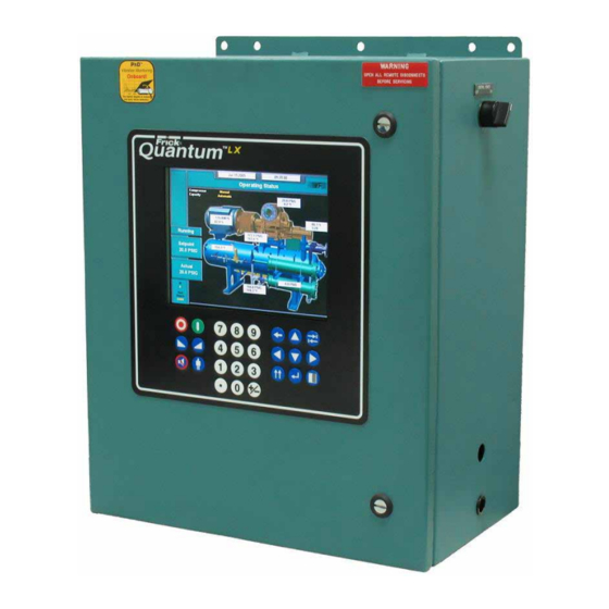
Frick QUANTUM LX Assembly And Maintenance Instructions
Compressor control panel
Hide thumbs
Also See for QUANTUM LX:
- Service manual (132 pages) ,
- Operation (84 pages) ,
- Maintenance manual (80 pages)

Related Manuals for Frick QUANTUM LX


Summary of Contents for Frick QUANTUM LX
- Page 1 S90-020 M/DEC 2004 File: SERVICE MANUAL - SECTION 90 Replaces: S90-020 M/AUG 2004 Dist: 3, 3a, 3b, 3c MAINTENANCE ® FRICK QUANTUM™ LX COMPRESSOR CONTROL PANEL VERSION 6.0x...
-
Page 2: Table Of Contents
® S90-020 M FRICK QUANTUM™ LX COMPRESSOR CONTROL PANEL Page 2 MAINTENANCE TABLE OF CONTENTS TABLE OF CONTENTS ............................2 THE QUANTUM™ LX CONTROL PANEL ENCLOSURE ..................6 INTRODUCTION TO THE QUANTUM™ LX CONTROL SYSTEM................6 QUANTUM™ CONTROLLER BOARD........................7 Introduction ................................ -
Page 3: Maintenance
IDENTIFYING THE TYPE OF DISPLAY ......................... 39 Display Replacement............................39 Display Assembly Component Replacement Guide..................39 TROUBLESHOOTING A PROBLEM THAT APPEARS UNEXPLAINABLE............40 ® TROUBLESHOOTING CHART FOR FRICK QUANTUM™ CONTROL PANEL ..........41 COMPRESSOR MODEL DIFFERENCES....................... 44 SETPOINT DATA SHEETS............................. 45 OPERATING VALUES ............................45 User Defined Setpoints .......................... - Page 4 ® S90-020 M FRICK QUANTUM™ LX COMPRESSOR CONTROL PANEL Page 4 MAINTENANCE Pressure................................52 Capacity Unload Assist ............................52 High Suction Pressure ............................52 Economizer ................................52 Balance Piston ..............................52 Oil Log ..................................52 Main Oil Injection ..............................52 Package Safeties ............................53 Low Oil Separator Temperature..........................53 Low Oil Temperature ............................53...
-
Page 5: Maintenance
INDEX ..................................112 THE FOLLOWING PUBLICATIONS ARE AVAILABLE Indicates an imminently hazardous DANGER ® situation which, if not avoided, will FROM THE FRICK WEBSITE frickcold.com result in death or serious injury. ® S90-020 O Frick Quantum™ LX Control Panel Operation -... -
Page 6: The Quantum™ Lx Control Panel Enclosure
The hardware portion (with the exception of the the Digital Boards can be found under the new international style keypad and cable) remains the DIGITAL BOARD section found later in this ® same. The Frick Quantum™ LX control system consists manual. of five major areas: •... -
Page 7: Quantum™ Controller Board
Because of the ever-increasing speed, memory eatures, and power of To troubleshoot the low-voltage side of the control circuits, ® microprocessors, Frick will continue to introduce the latest it is necessary to have the following tools: advancement in microprocessor control technology. -
Page 8: What Should Occur When Applying Power
® S90-020 M FRICK QUANTUM™ LX COMPRESSOR CONTROL PANEL Page 8 MAINTENANCE that the new board can be setup the same as the old one. WHAT IF THE OPERATING STATUS SCREEN IS NOT It is suggested that the operator first record all control SHOWN setpoints prior to board replacement. -
Page 9: Quantum™ Controller Board Pictorial
® FRICK QUANTUM™ LX COMPRESSOR CONTROL PANEL S90-020 M MAINTENANCE Page 9 QUANTUM™ CONTROLLER BOARD PICTORIAL Flash Card Socket (Located under board) Power PL11 Cable COM-2 COM-1 2 3 4 2 3 4 PL12 RS-422 RS-422 PL10 +5VDC COM-2 Cable... -
Page 10: Quantum™ Lx Flow Diagram - D.c. Voltage/Communications Harness (Special)
® S90-020 M FRICK QUANTUM™ LX COMPRESSOR CONTROL PANEL Page 10 MAINTENANCE (SPECIAL) QUANTUM™ LX FLOW DIAGRAM - D.C. VOLTAGE/COMMUNICATIONS HARNESS Digital Board 1 Power Supply (Condor shown). Digital Board 2 Factory Connector Analog Board 2 DC Power - I/O Communications... -
Page 11: Quantum™ Lx Flow Diagram - D.c. Voltage/Communications Harness (Standard)
® FRICK QUANTUM™ COMPRESSOR CONTROL PANEL S90-010 M MAINTENANCE Page 11 QUANTUM™ LX FLOW DIAGRAM - D.C. VOLTAGE/COMMUNICATIONS HARNESS (STANDARD) Digital Board 1 Power Supply (Condor shown). Digital Board 2 24 VDC Connections DC Power - I/O Communications Harness P/N 649D0069H01... -
Page 12: Digital Board
® S90-020 M FRICK QUANTUM™ LX COMPRESSOR CONTROL PANEL Page 12 MAINTENANCE DIGITAL BOARD The information that follows in this section can help locate (16-pin) will plug into each of the Digital and problems that can occur with Digital Input and Output Analog Boards in the system (up to four total). -
Page 13: Active Led
® FRICK QUANTUM™ LX COMPRESSOR CONTROL PANEL S90-020 M MAINTENANCE Page 13 will only be plugged into one of these connectors. Take energized (if the temperature of the oil is also sensed to the red (positive) probe of the DVM and carefully insert the be low. -
Page 14: Checking The Digital Inputs And Outputs
® modules are wired to a DIO connector plug. Position 3 the Frick Service Department. provides power and position 4 is a neutral on the DIO If the LED is on when it should be, check for connectors. -
Page 15: Digital I/O Board #1 Pictorial
® FRICK QUANTUM™ LX COMPRESSOR CONTROL PANEL S90-020 M MAINTENANCE Page 15 DIGITAL I/O BOARD #1 PICTORIAL INPUT MODULE OUTPUT MODULE POWER AMP794068-1 OUTPUT MODULE COMPRESSOR START/RUN COMPRESSOR AUXILIARY INPUT MODULE NEUTRAL OUTPUT MODULE OIL PUMP #1 START/RUN OIL PUMP #1 AUXILIARY... -
Page 16: Digital I/O Board #2 Pictorial
® S90-020 M FRICK QUANTUM™ LX COMPRESSOR CONTROL PANEL Page 16 MAINTENANCE DIGITAL I/O BOARD #2 PICTORIAL INPUT MODULE OUTPUT MODULE POWER AMP794068-1 OUTPUT MODULE READY TO RUN OPTIONAL REMOTE ENABLE OUTPUT MODULE OPTIONAL NEUTRAL INPUT MODULE REMOTE RUN/START/STOP OPTIONAL... -
Page 17: Digital Board Settings
® FRICK QUANTUM™ LX COMPRESSOR CONTROL PANEL S90-020 M MAINTENANCE Page 17 DIGITAL BOARD SETTINGS COMMUNICATIONS SETTINGS The following table is to be used when configuring the Quantum™ for external communications. 120 ohm long communications line termination. out* No termination. -
Page 18: Analog Board
Overview Enhanced - This board replaces the oiginal analog board effective June 2003. It features The Frick Quantum™ LX control panel is capable of twenty-four input channels, and eight output reading external analog devices, such as temperature channels. Rather than using physical jumpers to probes and pressure sensors. -
Page 19: Communications Led's
® FRICK QUANTUM™ LX COMPRESSOR CONTROL PANEL S90-020 M MAINTENANCE Page 19 Communications LED's The Analog Board requires the +5 Vdc for logic, the -12 Vdc for internal voltage reference, and +12 Vdc for The Quantum™ controller is in constant communication with the Analog (and Digital) Board(s). -
Page 20: Active Led
® S90-020 M FRICK QUANTUM™ LX COMPRESSOR CONTROL PANEL Page 20 MAINTENANCE supply being fed from the Quantum™ LX power supply. If software program within the Quantum™ LX is constantly the +5Vdc is present as stated earlier, then this LED will... -
Page 21: Analog Outputs
® FRICK QUANTUM™ LX COMPRESSOR CONTROL PANEL S90-020 M MAINTENANCE Page 21 Analog Outputs grounding problem. When a single transducer or cable is shorted to earth (or system) ground, this can show up as a whole assortment of problem channels. The easiest way... -
Page 22: Phd Vibration Analysis
If the alarm is not addressed, a shutdown will occur to prevent The Frick™ Enhanced Analog board has the built-in damage to the compressor. Likewise, if RTDs are used for capability to directly receive signals from vibration accelerometers and motor stator RTDs (100 Ω... -
Page 23: Current Transformer (Motor Amps)
® FRICK QUANTUM™ LX COMPRESSOR CONTROL PANEL S90-020 M MAINTENANCE Page 23 amps. If you are using an external current transformer, Current Transformer (Motor Amps) remove the jumper at Link 2, and connect the wiring to connector P8. If you intend on utilizing the on-board... -
Page 24: Enhanced Analog Board #1 Pictorial
® S90-020 M FRICK QUANTUM™ LX COMPRESSOR CONTROL PANEL Page 24 MAINTENANCE ENHANCED ANALOG BOARD #1 PICTORIAL Output CH. 8 - (Future) D5 - +24Vdc Power LED Output CH. 4 - Remote Control Setpoint Output Output CH. 7- (Future) Output CH. 3 - Slide Valve Position / Programmable Output Output CH. -
Page 25: Enhanced Analog Board #2 Pictorial
® FRICK QUANTUM™ LX COMPRESSOR CONTROL PANEL S90-020 M MAINTENANCE Page 25 ENHANCED ANALOG BOARD #2 PICTORIAL Output CH. 8 - Future Output CH. 4 - Condenser Variable D5 - +24Vdc Power LED Speed Output Output CH. 7- Future Output CH. 3 - Compressor Drive Variable Speed Output Output CH. -
Page 26: Enhanced Analog Board Settings
® S90-020 M FRICK QUANTUM™ LX COMPRESSOR CONTROL PANEL Page 26 MAINTENANCE ENHANCED ANALOG BOARD SETTINGS Communications The following table is to be used when configuring the Quantum™ for external communications. 120 ohm long communications line termination. Out * No termination. -
Page 27: Service Related Screens
® FRICK QUANTUM™ LX COMPRESSOR CONTROL PANEL S90-020 M MAINTENANCE Page 27 SERVICE RELATED SCREENS Digital Board Inputs and Outputs SCREEN NAME: Digital I/O. ACCESSING: Service… Digital DESCRIPTION: This Digital Service Screen has been provided to view the raw data from a Digital Board. -
Page 28: Analog Board Inputs And Outputs
® S90-020 M FRICK QUANTUM™ LX COMPRESSOR CONTROL PANEL Page 28 MAINTENANCE Analog Board Inputs and Outputs SCREEN NAME: Analog I/O. ACCESSING: Service… Analog DESCRIPTION: The Analog Service Screen has been provided to view the raw data from an Analog Board. -
Page 29: Motor Bump
® FRICK QUANTUM™ LX COMPRESSOR CONTROL PANEL S90-020 M MAINTENANCE Page 29 Motor Bump SCREEN NAME: Analog I/O. ACCESSING: Service… Motor Bump DESCRIPTION: The Motor Bump screen has been provided as a way for the service technician to verify proper motor rotation. -
Page 30: Software Maintenance
NOTE: Before accessing this screen, it is recommended that a USB adapter, a flash card reader and Frick flash card (P/N 649A0884Gxx) be plugged into the USB port of the Quantum™. -
Page 31: Miscelleneous Service Screens
® FRICK QUANTUM™ LX COMPRESSOR CONTROL PANEL S90-020 M MAINTENANCE Page 31 MISCELLENEOUS SERVICE SCREENS About SCREEN NAME: Sequencing. ACCESSING: About DESCRIPTION: The About screen shows the Analog and Digital boards that have been detected. If a board has lost communications, a shutdown will be issued. All outputs are turned off on a Digital Board that has lost communications. -
Page 32: Maintenance
® S90-020 M FRICK QUANTUM™ LX COMPRESSOR CONTROL PANEL Page 32 MAINTENANCE Maintenance SCREEN NAME: Maintenance. ACCESSING: Maintenance System Status… DESCRIPTION: This screen has been provided to aid the service technician with keeping track of system maintenance, and can be accessed from the service screen. From here, the service technician can view up to fifteen (15) user definable maintenance schedules. -
Page 33: Communications Screen
® FRICK QUANTUM™ LX COMPRESSOR CONTROL PANEL S90-020 M MAINTENANCE Page 33 Communications Screen SCREEN NAME: Maintenance. ACCESSING: Communications Setpoints… DESCRIPTION: The purpose of this screen being shown here is to indicate where the [Redetect I/O Boards] key is located. This selection provides a method to detect all connected Analog and Digital boards. -
Page 34: Power Supply Identification, Adjustment And Replacement
® S90-020 M FRICK QUANTUM™ LX COMPRESSOR CONTROL PANEL Page 34 MAINTENANCE POWER SUPPLY IDENTIFICATION, ADJUSTMENT AND REPLACEMENT IDENTIFICATION ADJUSTMENT ® All circuit boards within the Quantum™ control panel Frick Controls has used two power supplies in the require accurately adjusted DC voltages in order to Quantum™... -
Page 35: Replacement
Since the Power ® One is no longer available from Frick , an upgrade kit Ensure that the meter is set to the proper range (DC, 0-50 can be ordered that will adapt the Condor supply to V or equivalent), as well as observing proper wire polarity. -
Page 36: Quantum™ +5 Dc Voltage Measurement Location
® S90-020 M FRICK QUANTUM™ LX COMPRESSOR CONTROL PANEL Page 36 MAINTENANCE Quantum™ LX +5 DC Voltage Measurement Location Flash Card Socket (Located under board) PL11 COM-2 COM-1 2 3 4 2 3 4 +5 VDC (Red Lead) RS-422 PL12... -
Page 37: Quantum™ Panel Dc Power Supply Layout (Power-One)
® FRICK QUANTUM™ LX COMPRESSOR CONTROL PANEL S90-020 M MAINTENANCE Page 37 QUANTUM™ PANEL D.C. POWER SUPPLY LAYOUT (POWER-ONE) 120VAC Ground Neutral CAUTION Use only a screwdriver with an insulated shaft Pin 7 Pin 1 to perform adjustment (see NS-10-02 details). -
Page 38: Quantum™ Panel Dc Power Supply Layout (Condor)
® S90-020 M FRICK QUANTUM™ LX COMPRESSOR CONTROL PANEL Page 38 MAINTENANCE QUANTUM™ PANEL DC POWER SUPPLY LAYOUT (CONDOR) +5VDC Adjustment (cut away view) CAUTION Use only a screwdriver with an insulated shaft to perform adjustment (see NS-10-02 details). 120VAC... -
Page 39: Identifying The Type Of Display
Verify the jumper (link) settings per the table near the white display mounting plate to the other, as shown the bottom of this page. below. If the distance is approximately 12-3/4", the display FRICK ASSEM NO. 640C0052G01 / L.G. PHILIPS DISPLAY NO FRICK ASSEM NO. -
Page 40: Troubleshooting A Problem That Appears Unexplainable
“Lead” machine. 21. Make sure that you have a continuous ground ® • Check that you are using the Frick back to the power source. The ground connection recommended communications cable. See must be aluminum or copper. A conduit ground manual to match proper cable with type of will not work. -
Page 41: Troubleshooting Chart For Frick ® Quantum™ Control Panel
FRICK QUANTUM™ LX COMPRESSOR CONTROL PANEL S90-020 M MAINTENANCE Page 41 ® TROUBLESHOOTING CHART FOR FRICK QUANTUM™ CONTROL PANEL (REFER TO WIRING DIAGRAMS) SYMPTOM PROBABLE CAUSES and CORRECTIONS DISPLAY IS INOPERATIVE Check for power at the panel. See if any of the diagnostic lamps on the Main Board are blinking or any lights are blinking on the other boards. - Page 42 ® S90-020 M FRICK QUANTUM™ LX COMPRESSOR CONTROL PANEL Page 42 MAINTENANCE SYMPTOM PROBABLE CAUSES and CORRECTIONS OIL HEATERS DO NOT OPERATE The oil heaters should operate only when the compressor is NOT running and the oil separator temperature is not greater than or equal to the Oil Heater Off Above setpoint, and that the Oil Level input is made.
- Page 43 ® FRICK QUANTUM™ LX COMPRESSOR CONTROL PANEL S90-020 M MAINTENANCE Page 43 SYMPTOM PROBABLE CAUSES and CORRECTIONS SLIDE STOP DOES NOT INCREASE Verify that the Slide Stop is in the AUTO mode and that the VI Ratio is calling and/or DECREASE* Some Compressor for a VI increase or decrease.
-
Page 44: Compressor Model Differences
The current transformer is used to convert the AC motor amps to a DC voltage UNLOAD) OCCURS AT HIGH MOTOR signal for the microprocessor. If the %FLA reading from the Operating display ® AMPS is incorrect, contact the Frick Service Department. MOTOR LOAD CONTROL(FORCED... -
Page 45: Setpoint Data Sheets
® FRICK QUANTUM™ LX COMPRESSOR CONTROL PANEL S90-020 M MAINTENANCE Page 45 SETPOINT DATA SHEETS In most cases, updating software on the Quantum™ LX panel will require clearing the current setpoints and data stored in the nonvolatile memory on the main board. It is suggested that the operator first record all control setpoints prior to performing program upgrades. -
Page 46: Modes
® S90-020 M FRICK QUANTUM™ LX COMPRESSOR CONTROL PANEL Page 46 MAINTENANCE MODES Manual Automatic Remote Comm Remote I/O Remote Seq. Compressor Manual Automatic Remote Comm Remote I/O Remote 4-20 Remote Seq. Capacity Manual Automatic Volume Regualtion 1 Regulation 2... -
Page 47: System Status
® FRICK QUANTUM™ LX COMPRESSOR CONTROL PANEL S90-020 M MAINTENANCE Page 47 SYSTEM STATUS Trending Setup Real Time History (Channel) (Channel) 1 2 3 4 5 6 7 8 1 2 3 4 5 6 7 8 Capactiy Slide Position... -
Page 48: Maintenance
® S90-020 M FRICK QUANTUM™ LX COMPRESSOR CONTROL PANEL Page 48 MAINTENANCE SYSTEM STATUS (Continued) Maintenance Name Service Every Next Scheduled At Oil Analysis Change Filters Clean Oil Strainers Maintenance Clean Lqd Strainers Required Setpoints Change Coelescers Clean Suction Screen... -
Page 49: Setpoints
® FRICK QUANTUM™ LX COMPRESSOR CONTROL PANEL S90-020 M MAINTENANCE Page 49 SETPOINTS Capacity Control Setpoints Setpoint Setpoint Proportional Band High Proportional Band Low Capacity Control Dead Band High Dead Band Low Cycle Time High Cycle Time Low Start Pressure... -
Page 50: Control Mode # 3
® S90-020 M FRICK QUANTUM™ LX COMPRESSOR CONTROL PANEL Page 50 MAINTENANCE SETPOINTS (Continued) Capacity Control Setpoints Setpoint Setpoint Proportional Band High Proportional Band Low Capacity Control Dead Band High Dead Band Low Cycle Time High Cycle Time Low Start Pressure... -
Page 51: Sequencing
® FRICK QUANTUM™ LX COMPRESSOR CONTROL PANEL S90-020 M MAINTENANCE Page 51 SETPOINTS (Continued) Sequencing Minimum High Stage System Link Disabled Enabled Setpoint Run Time None System 2 System 3 System 1 Setup Compressor Mode Capacity Mode Panel Type System 1... -
Page 52: Compressor Safeties Setpoints
® S90-020 M FRICK QUANTUM™ LX COMPRESSOR CONTROL PANEL Page 52 MAINTENANCE SETPOINTS (Continued) Compressor Safeties Setpoints Setpoint Load Inhibit Force Unload High Discharge Warning Temperature Warning Delay Shutdown Shutdown Delay Starting Differential Pressure Below ___________ Load Inhibit Force Unload... -
Page 53: Package Safeties
® FRICK QUANTUM™ LX COMPRESSOR CONTROL PANEL S90-020 M MAINTENANCE Page 53 SETPOINTS (Continued) Package Safeties Setpoint Warning Warning Delay Low Oil Separator Temperature Shutdown Shutdown Delay Warning Warning Delay Low Oil Temperature Shutdown Shutdown Delay Warning Warning Delay High Oil Temperature... -
Page 54: Drive
® S90-020 M FRICK QUANTUM™ LX COMPRESSOR CONTROL PANEL Page 54 MAINTENANCE SETPOINTS (Continued) Drive Setpoint Motor Amps Volts Service Factor Name Plate Horse Power CT Factor Recycle Delay Load Inhibit Force Unload Warning High Motor Amps Warning Delay Shutdown... -
Page 55: Condenser
® FRICK QUANTUM™ LX COMPRESSOR CONTROL PANEL S90-020 M MAINTENANCE Page 55 SETPOINTS (Continued) Condenser Setpoint Condenser Control Setpoint Step #1 Step #2 CONDENSER Step #3 CONTROL SETPOINTS Step #4 Step Up Deadband Step Up Delay Step Down Deadband Step Down Delay... -
Page 56: Pid Setup
® S90-020 M FRICK QUANTUM™ LX COMPRESSOR CONTROL PANEL Page 56 MAINTENANCE SETPOINTS (Continued) PID Setup Page 1 PID 1 PID 2 PID 3 PID 4 Name Disabled Disabled Disabled Disabled Control Running Running Running Running Always Always Always Always... -
Page 57: Pid Setup
® FRICK QUANTUM™ LX COMPRESSOR CONTROL PANEL S90-020 M MAINTENANCE Page 57 SETPOINTS (Continued) PID Setup Page 2 PID 5 PID 6 PID 7 PID 8 Name Disabled Disabled Disabled Disabled Control Running Running Running Running Always Always Always Always... -
Page 58: Communications
® S90-020 M FRICK QUANTUM™ LX COMPRESSOR CONTROL PANEL Page 58 MAINTENANCE SETPOINTS (Continued) Communications ID Number: _________ (range: 0 - 99) Baud rate Data Bits Stop Bits Parity Connection Type Protocol Map File 1200 None None None 2400 Even... -
Page 59: Auxiliary Analog Input Safeties
® FRICK QUANTUM™ LX COMPRESSOR CONTROL PANEL S90-020 M MAINTENANCE Page 59 SETPOINTS (Continued) Auxiliary Analog Input Safeties Page 1 High High High Auxiliary Warning Warning Shutdown Shutdown Warning Warning Shutdown Shutdown Setpoint Delay Setpoint Delay Setpoint Delay Setpoint Delay... -
Page 60: Digital Input Configuration
® S90-020 M FRICK QUANTUM™ LX COMPRESSOR CONTROL PANEL Page 60 MAINTENANCE SETPOINTS (Continued) Digital Input Configuration Device Source Activity Auxiliary Name I/O Channel Delay Auxiliary Input 1 Auxiliary Input 2 Auxiliary Input 3 Auxiliary Input 4 Auxiliary Input 5... -
Page 61: Panel
® FRICK QUANTUM™ LX COMPRESSOR CONTROL PANEL S90-020 M MAINTENANCE Page 61 SETPOINTS (Continued) Panel Panel Heater Disabled Starting Running Permissive Start Disabled Enabled Remote Enable Run Hours: ______ Disabled Enabled Interlock Disabled Enabled Input Module Capacity Mode Selection... -
Page 62: Calibration
® S90-020 M FRICK QUANTUM™ LX COMPRESSOR CONTROL PANEL Page 62 MAINTENANCE CALIBRATION Pressure Device Range Sensor Signal Source Pressure Current Transducer Value High Channel Suction Discharge Balance Piston Main Oil Injection Economizer System Discharge Intermediate Filter Manifold CALIBRATION (Continued) -
Page 63: Capacity
® FRICK QUANTUM™ LX COMPRESSOR CONTROL PANEL S90-020 M MAINTENANCE Page 63 CALIBRATION (Continued) Capacity Device Sensor Signal Source Capacity Low Value High Value Channel Capacity Travel ________ CALIBRATION (Continued) Volume Device Sensor Signal Source Volume Low Value High Value... -
Page 64: Analog Output
® S90-020 M FRICK QUANTUM™ LX COMPRESSOR CONTROL PANEL Page 64 MAINTENANCE CALIBRATION (CONTINUED) Analog Output Output Channel Device Source Analog Output 4 mA 20 mA Device Channel Capactiy Slide Position Volume Slide Position Suction Pressure Discharge Pressure Compressor Oil Pressure... -
Page 65: Auxiliary Analogs
® FRICK QUANTUM™ LX COMPRESSOR CONTROL PANEL S90-020 M MAINTENANCE Page 65 CALIBRATION (CONTINUED) Auxiliary Analogs - Page 1 Range Current Auxiliary Analogs Name I/O Channel Value High Auxiliary Input 1 Auxiliary Input 2 Auxiliary Input 3 Auxiliary Input 4... -
Page 66: Configuration
® S90-020 M FRICK QUANTUM™ LX COMPRESSOR CONTROL PANEL Page 66 MAINTENANCE CONFIGURATION Compressor Date: (Always set to current date) Time: (Always set to current time) Miscelleneous: Disabled Enabled Sequencing Disbled Running Always Condenser Screen Saver: ________ Capactiy Regulation 1... -
Page 67: Package
® FRICK QUANTUM™ LX COMPRESSOR CONTROL PANEL S90-020 M MAINTENANCE Page 67 Package RWBII R113 R114 R1150 RXF 12-50 RXF 58-101 RDB, 4-STEP R1270 RDB, 3-STEP GSV II R134a Compressor model R13b1 GSB 3-STEP R142b R170 R218 YORK S-7 YORK S-5... -
Page 68: Internet
® S90-020 M FRICK QUANTUM™ LX COMPRESSOR CONTROL PANEL Page 68 MAINTENANCE CONFIGURATION (Continued) Internet IP Data Fixed (Static) DHSP (Dynamic) Address Type IP Address: ______ ______ ______ ______ Gateway Address: ______ ______ ______ ______ Subnet Mask: ______ ______ ______ ______... -
Page 69: Session
® FRICK QUANTUM™ LX COMPRESSOR CONTROL PANEL S90-020 M MAINTENANCE Page 69 SESSION User level ________ Password ________ English French Chinese Portugese Language Kpaa BarA PSIA PSIG Pressure units Celcius (°C) Fahrenheit (°F) Temperature units European Date Format SERVICE Motor Bump... -
Page 70: Quantum™ Drawings
® S90-020 M FRICK QUANTUM™ LX COMPRESSOR CONTROL PANEL Page 70 MAINTENANCE QUANTUM™ DRAWINGS This table lists the numbers for the drawings that appear on the following pages. The drawings shown here are the latest revision as of the printing of this manual. These drawings appear here for reference purposes only, and are subject to change without notice. -
Page 71: Control Center Assemblies
® FRICK QUANTUM™ LX COMPRESSOR CONTROL PANEL S90-020 M MAINTENANCE Page 71 RDB / RWB II / RWF / RXF (58 - 101) CONTROL CENTER ASSEMBLY (Sheet 1 of 4) DANGER Do not drill through top pf panel. This drawing appears here for reference purposes only, and is subject to change without notice. When installing, or servicing... - Page 72 ® S90-020 M FRICK QUANTUM™ LX COMPRESSOR CONTROL PANEL Page 72 MAINTENANCE RDB / RWB II / RWF / RXF (58 - 101) CONTROL CENTER ASSEMBLY (Sheet 2 of 4) This drawing appears here for reference purposes only, and is subject to change without notice. When installing, or servicing...
- Page 73 ® FRICK QUANTUM™ LX COMPRESSOR CONTROL PANEL S90-020 M MAINTENANCE Page 73 RDB / RWB II / RWF / RXF (58 - 101) CONTROL CENTER ASSEMBLY (Sheet 3 of 4) This drawing appears here for reference purposes only, and is subject to change without notice. When installing, or servicing...
- Page 74 ® S90-020 M FRICK QUANTUM™ LX COMPRESSOR CONTROL PANEL Page 74 MAINTENANCE RDB / RWB II / RWF / RXF (58 - 101) CONTROL CENTER ASSEMBLY (Sheet 4 of 4) This drawing appears here for reference purposes only, and is subject to change without notice. When installing, or servicing...
-
Page 75: Rxf (12-50) Retrofit Mounting
® FRICK QUANTUM™ LX COMPRESSOR CONTROL PANEL S90-020 M MAINTENANCE Page 75 RXF (12-50) RETROFIT MOUNTING This drawing appears here for reference purposes only, and is subject to change without notice. When installing, or servicing equipment, always refer to the actual drawings that are included with the control panel for the latest information. -
Page 76: Wiring Diagrams
® S90-020 M FRICK QUANTUM™ LX COMPRESSOR CONTROL PANEL Page 76 MAINTENANCE WIRING DIAGRAM – RWF (Sheet 1 of 4) This drawing appears here for reference purposes only, and is subject to change without notice. When installing, or servicing equipment, always refer to the actual drawings that are included with the control panel for the latest information. - Page 77 ® FRICK QUANTUM™ LX COMPRESSOR CONTROL PANEL S90-020 M MAINTENANCE Page 77 WIRING DIAGRAM – RWF (Sheet 2 of 4) This drawing appears here for reference purposes only, and is subject to change without notice. When installing, or servicing equipment, always refer to the actual drawings that are included with the control panel for the latest information.
- Page 78 ® S90-020 M FRICK QUANTUM™ LX COMPRESSOR CONTROL PANEL Page 78 MAINTENANCE WIRING DIAGRAM – RWF (Sheet 3 of 4) This drawing appears here for reference purposes only, and is subject to change without notice. When installing, or servicing equipment, always refer to the actual drawings that are included with the control panel for the latest information.
- Page 79 ® FRICK QUANTUM™ LX COMPRESSOR CONTROL PANEL S90-020 M MAINTENANCE Page 79 WIRING DIAGRAM – RWF (Sheet 4 of 4) This drawing appears here for reference purposes only, and is subject to change without notice. When installing, or servicing equipment, always refer to the actual drawings that are included with the control panel for the latest information.
-
Page 80: Rwb Ii
® S90-020 M FRICK QUANTUM™ LX COMPRESSOR CONTROL PANEL Page 80 MAINTENANCE WIRING DIAGRAM -- - RWB II (Sheet 1 of 4) This drawing appears here for reference purposes only, and is subject to change without notice. When installing, or servicing... - Page 81 ® FRICK QUANTUM™ LX COMPRESSOR CONTROL PANEL S90-020 M MAINTENANCE Page 81 WIRING DIAGRAM -- - RWB II (Sheet 2 of 4) This drawing appears here for reference purposes only, and is subject to change without notice. When installing, or servicing...
- Page 82 ® S90-020 M FRICK QUANTUM™ LX COMPRESSOR CONTROL PANEL Page 82 MAINTENANCE WIRING DIAGRAM -- - RWB II (Sheet 3 of 4) This drawing appears here for reference purposes only, and is subject to change without notice. When installing, or servicing...
- Page 83 ® FRICK QUANTUM™ LX COMPRESSOR CONTROL PANEL S90-020 M MAINTENANCE Page 83 WIRING DIAGRAM -- - RWB II (Sheet 4 of 4) This drawing appears here for reference purposes only, and is subject to change without notice. When installing, or servicing...
-
Page 84: Rxf (12-50)
® S90-020 M FRICK QUANTUM™ LX COMPRESSOR CONTROL PANEL Page 84 MAINTENANCE WIRING DIAGRAM – RXF (12-50) - (Sheet 1 of 4) This drawing appears here for reference purposes only, and is subject to change without notice. When installing, or servicing... - Page 85 ® FRICK QUANTUM™ LX COMPRESSOR CONTROL PANEL S90-020 M MAINTENANCE Page 85 WIRING DIAGRAM – RXF (12-50) - (Sheet 2 of 4) This drawing appears here for reference purposes only, and is subject to change without notice. When installing, or servicing...
- Page 86 ® S90-020 M FRICK QUANTUM™ LX COMPRESSOR CONTROL PANEL Page 86 MAINTENANCE WIRING DIAGRAM – RXF (12-50) - (Sheet 3 of 4) This drawing appears here for reference purposes only, and is subject to change without notice. When installing, or servicing...
- Page 87 ® FRICK QUANTUM™ LX COMPRESSOR CONTROL PANEL S90-020 M MAINTENANCE Page 87 WIRING DIAGRAM – RXF (12-50) - (Sheet 4 of 4) This drawing appears here for reference purposes only, and is subject to change without notice. When installing, or servicing...
-
Page 88: Rxf (58-101)
® S90-020 M FRICK QUANTUM™ LX COMPRESSOR CONTROL PANEL Page 88 MAINTENANCE WIRING DIAGRAM – RXF (58-101) (Sheet 1 of 4) This drawing appears here for reference purposes only, and is subject to change without notice. When installing, or servicing... - Page 89 ® FRICK QUANTUM™ LX COMPRESSOR CONTROL PANEL S90-020 M MAINTENANCE Page 89 WIRING DIAGRAM – RXF (58-101) (Sheet 2 of 4) This drawing appears here for reference purposes only, and is subject to change without notice. When installing, or servicing...
- Page 90 ® S90-020 M FRICK QUANTUM™ LX COMPRESSOR CONTROL PANEL Page 90 MAINTENANCE WIRING DIAGRAM – RXF (58-101) (Sheet 3 of 4) This drawing appears here for reference purposes only, and is subject to change without notice. When installing, or servicing...
- Page 91 ® FRICK QUANTUM™ LX COMPRESSOR CONTROL PANEL S90-020 M MAINTENANCE Page 91 WIRING DIAGRAM – RXF (58-101) (Sheet 4 of 4) This drawing appears here for reference purposes only, and is subject to change without notice. When installing, or servicing...
-
Page 92: Rdb
® S90-020 M FRICK QUANTUM™ LX COMPRESSOR CONTROL PANEL Page 92 MAINTENANCE WIRING DIAGRAM – RDB (Sheet 1 of 4) This drawing appears here for reference purposes only, and is subject to change without notice. When installing, or servicing equipment, always refer to the actual drawings that are included with the control panel for the latest information. - Page 93 ® FRICK QUANTUM™ LX COMPRESSOR CONTROL PANEL S90-020 M MAINTENANCE Page 93 WIRING DIAGRAM – RDB (Sheet 2 of 4) This drawing appears here for reference purposes only, and is subject to change without notice. When installing, or servicing equipment, always refer to the actual drawings that are included with the control panel for the latest information.
- Page 94 ® S90-020 M FRICK QUANTUM™ LX COMPRESSOR CONTROL PANEL Page 94 MAINTENANCE WIRING DIAGRAM – RDB (Sheet 3 of 4) This drawing appears here for reference purposes only, and is subject to change without notice. When installing, or servicing equipment, always refer to the actual drawings that are included with the control panel for the latest information.
- Page 95 ® FRICK QUANTUM™ LX COMPRESSOR CONTROL PANEL S90-020 M MAINTENANCE Page 95 WIRING DIAGRAM – RDB (Sheet 4 of 4) This drawing appears here for reference purposes only, and is subject to change without notice. When installing, or servicing equipment, always refer to the actual drawings that are included with the control panel for the latest information.
-
Page 96: Phd
® S90-020 M FRICK QUANTUM™ LX COMPRESSOR CONTROL PANEL Page 96 MAINTENANCE WIRING DIAGRAM PHD (Sheet 1 of 2) This drawing appears here for reference purposes only, and is subject to change without notice. When installing, or servicing equipment, always refer to the actual drawings that are included with the control panel for the latest information. - Page 97 ® FRICK QUANTUM™ LX COMPRESSOR CONTROL PANEL S90-020 M MAINTENANCE Page 97 WIRING DIAGRAM PHD (Sheet 2 of 2) This drawing appears here for reference purposes only, and is subject to change without notice. When installing, or servicing equipment, always refer to the actual drawings that are included with the control panel for the latest information.
-
Page 98: Standard Digital I/O Board 2
® S90-020 M FRICK QUANTUM™ LX COMPRESSOR CONTROL PANEL Page 98 MAINTENANCE WIRING DIAGRAM - STANDARD DIGITAL I/O BOARD 2 (Sheet 1 of 2) This drawing appears here for reference purposes only, and is subject to change without notice. When installing, or servicing... - Page 99 ® FRICK QUANTUM™ LX COMPRESSOR CONTROL PANEL S90-020 M MAINTENANCE Page 99 WIRING DIAGRAM - STANDARD DIGITAL I/O BOARD 2 (Sheet 2 of 2) This drawing appears here for reference purposes only, and is subject to change without notice. When installing, or servicing...
-
Page 100: Special Digital I/O Board 2
® S90-020 M FRICK QUANTUM™ LX COMPRESSOR CONTROL PANEL Page 100 MAINTENANCE WIRING DIAGRAM - SPECIAL DIGITAL I/O BOARD 2 (Sheet 1 of 2) This drawing appears here for reference purposes only, and is subject to change without notice. When installing, or servicing... - Page 101 ® FRICK QUANTUM™ LX COMPRESSOR CONTROL PANEL S90-020 M MAINTENANCE Page 101 WIRING DIAGRAM - SPECIAL DIGITAL I/O BOARD 2 (Sheet 2 of 2) This drawing appears here for reference purposes only, and is subject to change without notice. When installing, or servicing...
-
Page 102: Standard Analog I/O Board 2
® S90-020 M FRICK QUANTUM™ LX COMPRESSOR CONTROL PANEL Page 102 MAINTENANCE WIRING DIAGRAM STANDARD ANALOG I/O BOARD 2 (Sheet 1 of 2) This drawing appears here for reference purposes only, and is subject to change without notice. When installing, or servicing... - Page 103 ® FRICK QUANTUM™ LX COMPRESSOR CONTROL PANEL S90-020 M MAINTENANCE Page 103 WIRING DIAGRAM STANDARD ANALOG I/O BOARD 2 (Sheet 2 of 2) This drawing appears here for reference purposes only, and is subject to change without notice. When installing, or servicing...
-
Page 104: Special Analog I/O Board 2
® S90-020 M FRICK QUANTUM™ LX COMPRESSOR CONTROL PANEL Page 104 MAINTENANCE WIRING DIAGRAM - SPECIAL ANALOG I/O BOARD 2 (Sheet 1 of 2) This drawing appears here for reference purposes only, and is subject to change without notice. When installing, or servicing... - Page 105 ® FRICK QUANTUM™ LX COMPRESSOR CONTROL PANEL S90-020 M MAINTENANCE Page 105 WIRING DIAGRAM - SPECIAL ANALOG I/O BOARD 2 (Sheet 2 of 2) This drawing appears here for reference purposes only, and is subject to change without notice. When installing, or servicing...
-
Page 106: I/O & D.c. Power Harness
® S90-020 M FRICK QUANTUM™ LX COMPRESSOR CONTROL PANEL Page 106 MAINTENANCE QUANTUM™ I/O & D.C. POWER HARNESS (SPECIAL PANELS) This drawing appears here for reference purposes only, and is subject to change without notice. When installing, or servicing equipment, always refer to the actual drawings that are included with the control panel for the latest information. -
Page 107: Standard Panels
® FRICK QUANTUM™ LX COMPRESSOR CONTROL PANEL S90-020 M MAINTENANCE Page 107 QUANTUM™ I/O & D.C. POWER HARNESS (STANDARD PANELS) This drawing appears here for reference purposes only, and is subject to change without notice. When installing, or servicing equipment, always refer to the actual drawings that are included with the control panel for the latest information. -
Page 108: Communications Wiring Diagrams
® S90-020 M FRICK QUANTUM™ LX COMPRESSOR CONTROL PANEL Page 108 MAINTENANCE COMMUNICATIONS WIRING DIAGRAMS TO CUSTOMER REMOTE COMPUTER/DCS RS-485 COMMUNICATIONS QUANTUM™ 1 OR 2 QUANTUM™ 3 OR 4 QUANTUM™ 3 OR 4 QUANTUM™ 3 OR 4 To Customer COM-2 (TB2) -
Page 109: Point-To-Point Field Wiring Diagram
CONDUIT GROUNDS ARE NOT ACCEPTABLE. WIRING MUST LATEST EDITION OF THE NEC AND LOCAL CODES. ALL CONTROL VOLTAGE WIRING STRANDED COPPER WIRE. HI-LEVEL CUTOUT AND/OR OTHER FIELD FRICK QUANTUM LX ENCLOSURE SAFETY CUTOUTS AS REQUIRED. OIL PUMP COMP MOTOR MOTOR... -
Page 110: Pressure Transducer Conversion Data
® S90-020 M FRICK QUANTUM™ LX COMPRESSOR CONTROL PANEL Page 110 MAINTENANCE PRESSURE TRANSDUCER CONVERSION DATA (Data Instruments Model SA) 100 psi 200 psi 300 psi 500 psi Sensor Range - psig* Range - psig* Range - psig* Range - psig*... - Page 111 640C0026G02 Analog Board #2 (Original) 640C0057G01 Analog Board #1 (Enhanced) 640C0057G02 Analog Board #2 (Enahnced) Keypads ® 640D01860H01 Keypad/overlay Frick ’s Circuit Breakers 649A0883H10 10 Amp circuit breaker 649A0883H16 16 Amp circuit breaker 649A0883H20 20 Amp circuit breaker Quantum™ Controllers 649C1083G01 Upgrade from Quantum™...
-
Page 112: Index
® S90-020 M FRICK QUANTUM™ LX COMPRESSOR CONTROL PANEL Page 112 MAINTENANCE INDEX About Screen..............31 Factory Default ..............8 AC ..................8 Factory Setpoints ............45 Active LED................ 8 Factory Setup..............8, 45 Analog Board....... 12, 18-21, 28, 29, 31-33 Failed Communications..........12, 19 Analog Board Description..........18... - Page 113 ® FRICK QUANTUM™ LX COMPRESSOR CONTROL PANEL S90-020 M MAINTENANCE Page 113 Motor Current Transformer ..........40 RX (receive) .............. 12, 19 Motor Starter Panel ............40 Samsung..............8, 9, 39 NEC ................8, 9, 39 Scheduled Maintenance ..........32 Negative..............13, 19 Screen ....7, 8, 12, 14, 17, 19, 21, 27-29, 31-33, 44 Neutral ................7, 14...
- Page 114 ® S90-020 M FRICK QUANTUM™ LX COMPRESSOR CONTROL PANEL Page 114 MAINTENANCE...
- Page 115 ® FRICK QUANTUM™ LX COMPRESSOR CONTROL PANEL S90-020 M MAINTENANCE Page 115...
- Page 116 ® S90-020 M FRICK QUANTUM™ LX COMPRESSOR CONTROL PANEL Page 116 MAINTENANCE YORK Refrigeration Systems 100 CV Avenue, P.O. Box 997 Waynesboro, Pennsylvania USA 17268-0997 Phone: 717-762-2121 • Fax: 717-762-8624 • www.frickcold.com ® Copyright 2004 YORK Refrigeration Systems...
Need help?
Do you have a question about the QUANTUM LX and is the answer not in the manual?
Questions and answers