Table of Contents
Advertisement
Quick Links
Advertisement
Table of Contents

Related Manuals for INNO Instrument View 8+


Summary of Contents for INNO Instrument View 8+
- Page 1 User's Manual Version:V0.01...
-
Page 2: Table Of Contents
User’s Manual INNO Instrument, Inc. Contents Preface............................4 Chapter1 Technical Parameters....................5 Applicable Fiber Type........................5 Splice Loss............................5 Splice Mode...........................5 Heat Oven.............................5 Power Supply..........................5 Size and Weight.........................6 Environmental Conditions......................6 Others............................6 Battery precautions........................6 Chapter 2 Installation........................7 Safety Warning and Precautions....................7 Safety Warnings........................7 Maintenance and External Care Precautions................8 Transport and Storage Precautions..................8... - Page 3 User’s Manual INNO Instrument, Inc. Inspecting the Fibers..................14 Splicing......................15 How to Protect the Splice..................15 Steps for Heating....................15 Chapter 4 Splice Mode..................17 Displaying the Current Splice Mode..............17 Selecting a Splice Mode..................18 Steps of Normal Splicing Program................19 Pre-Fusion......................19 Fusion........................19 Splicing Process.....................19 Parameters for Normal Splicing Process..............20 Chapter 5 Splice Option..................22...
- Page 4 User’s Manual INNO Instrument, Inc. Motor Calibration..................29 Operation Procedure..................30 Arc Calibration......................30 Operation procedure..................30 Electrode Setting....................30 Update Software..................30 Chapter 8 Other Functions & Utilities..............31 WIFI Connection.....................31 Data Storage ......................34 Display Splice Record..................34 Delete Splice Record...................34 Cancel Data Storage..................34 System Setting.......................34 Monitor Position....................35 Power Save Option..................36...
-
Page 5: Preface
User’s Manual INNO Instrument, Inc. Preface Thank you for choosing VIEW8+ Arc Fusion Splicer from INNO Instrument. VIEW8+ adopts innovative product design and exquisite manufacturing technology so as to deliver unprecedented splicing experience to customers. The totally new technology greatly reduces splicing and heating time, and advanced estimation method and alignment technique ensure the accuracy of splice loss estimation. -
Page 6: Chapter1 Technical Parameters
User’s Manual INNO Instrument, Inc. Chapter1 Technical Parameters Applicable Fiber Type * SM(ITU-TG.652&G.657)/MM(ITU-TG.651)/DS(ITU-TG.653)/NZDS(ITU- TG.655) * Fiber count: Single * Applicable fiber / cable diameter: 0.25mm to 3.0mm/Indoor Cable * Applicable fiber diameter: Cladding diameter: 80mm to 150μm / Coating diameter:125 to 1000μm Splice Loss Same fiber is spliced, measured by cut-back method relevant to ITU-T standard. -
Page 7: Environmental Conditions
User’s Manual INNO Instrument, Inc. Environmental Conditions * Operating conditions: altitude: 0 to 5000m, relative humidity: 0 to 95%, temperature: -10 to50 ℃ , the maximum wind velocity: 15m / s; * Storage conditions: relative humidity: 0 to 95%, temperature: -20 to 60 ℃ , battery: -20 to 30 ℃... -
Page 8: Chapter 2 Installation
VIEW8+ at any time. Any behaviors that do not follow the warnings and cautions will break the safety standard about design, manufacture, and usage of the fusion splicer. INNO Instrument will not take the responsibility for those consequences caused by misuse! Operational Safety Warnings ①... -
Page 9: Maintenance And External Care Precautions
User’s Manual INNO Instrument, Inc. Maintenance and External Care Precautions ① Always avoid using hard objects to clean V-grooves and electrodes. ② Always avoid using acetone, thinner, benzol or alcohol when cleaning any part of the splicer, except for the places advised. -
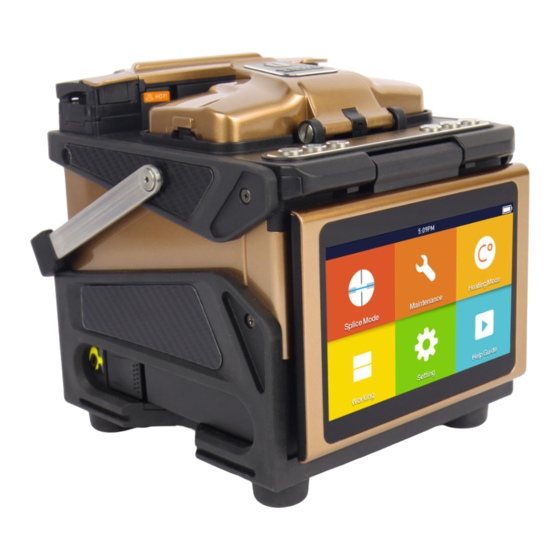
Page 10: Overview Of External Parts
User’s Manual INNO Instrument, Inc. Overview of External Parts Control buttons ON/OFF button Heat oven Handle Display Battery USB 2.0 MINI USB Power supply connector PAGE... -
Page 11: Power Supply Method
User’s Manual INNO Instrument, Inc. Power Supply Method Battery 1. Following is the way of installing a battery. Shut off fusion splicer. Press on release button at lateral, drawing power supply unit out of the fusion splicer. Release Button Place power supply unit into power unit slot until you push it into the right place. -
Page 12: Chapter 3 Basic Operation
User’s Manual INNO Instrument, Inc. Chapter 3 - Basic Operation Turn On the Splicer Press button on the operation panel, and wait the splicer to be turned on and move to Workbench page. Adjust Monitor Position Users can adjust the monitor position by moving it with a desired angle for purpose of operation convenience. -
Page 13: Adjust Lcd Backlight Brightness
User’s Manual INNO Instrument, Inc. In the initial interface,press 【O】button on the operation panel to enter monitor brightness adjustment interface, and press to adjust the brightness until a clear image can be seen. Note: The LCD monitor is a precise component produced by manufacturing factory under strict quality control. -
Page 14: Preparing The Fiber
3.Cleave the fiber In order to ensure the best splicing result, cleave the fbers with high precision cleaver such as INNO Instrument V series fiber cleaver, and strictly control the cleaving lengths shown as below. Note: always remember to slip a... -
Page 15: How To Make A Splice
User’s Manual INNO Instrument, Inc. How to Make a Splice Put the optical fiber in Note: Make sure to avoid sliding ① Open the safety shield. the fibers along V-grooves, ② Raise the fiber clamps. but rather position them over ③... -
Page 16: Splicing
User’s Manual INNO Instrument, Inc. Note:The fibers are checked automatically when you press Set button. The splicer automatically focuses the fibers and checks for damage or dust particles. Splicing ① Select any appropriate Note: If the splicer is set as “Auto mode”, splice mode. - Page 17 User’s Manual INNO Instrument, Inc. Open the heat oven lid Splicing position move into heat oven clamp PAGE...
-
Page 18: Chapter 4 Splice Mode
User’s Manual INNO Instrument, Inc. Chapter 4 Splice Mode VIEW8+ has an intuitive and simple but very powerful program structure to operate. Splice programs define arc currents, splice times as well as various parameters used when performing a splice. Therefore, it is essential to select the correct splice program. -
Page 19: Selecting A Splice Mode
User’s Manual INNO Instrument, Inc. Selecting a Splice Mode ① Select [Splice mode] from the main menu. ② Select [Splice mode] and select [Select splice mode]. ③ Select an appropriate splice mode ④ Selected splice mode appears on the screen. -
Page 20: Steps Of Normal Splicing Program
User’s Manual INNO Instrument, Inc. General Splicing Steps This section explains the steps involved in automatic splicing process and describes how various program parameters are related to this process. The normal splicing process can be divided into two sections: pre-fusion and fusion. -
Page 21: Parameters For Normal Splicing Process
User’s Manual INNO Instrument, Inc. Parameters for Normal Splicing Process Parameter Description A list of splice modes stored in the splicer database is displayed. Upon inputting the appropriate mode, the selected Template splice mode stored in database area is copied to a selected splice mode in user-programmable area. - Page 22 User’s Manual INNO Instrument, Inc. Parameter Description Set the end-face gap between the left and right fibers at the time of aligning and pre-fusion discharge. Set the overlap amount of fibers at the fiber propelling stage. Relatively small [Overlap] is recommended if [Preheat Arc...
-
Page 23: Chapter 5 Splice Option
User’s Manual INNO Instrument, Inc. Chapter 5 - Splice Option Splice Mode Setting 1 Select [Splice option] in menu. 2 Select a parameter to be changed. Parameter Description If “Auto start” is set to ON, splicing starts automatically Auto start as soon as the wind protector is closed. - Page 24 User’s Manual INNO Instrument, Inc. Parameter Description Fiber immage on screen Paulse 1 Align Set the displaying method of the fiber image on the screen Paulse 2 during splicing operation. Estimate Gap set PAGE...
-
Page 25: Chapter 6 Heater Mode
User’s Manual INNO Instrument, Inc. Chapter 6 - Heater Mode The splicer provides max 32 heat modes including 6 heat modes preset by INNO Instrument and the rest that can be defined by users. Select a heating mode that best matches with the protection sleeve used. -
Page 26: Edit Heater Mode
User’s Manual INNO Instrument, Inc. ③ Select heat mode. ④ S e l e c t e d h e a t m o d e appears on the screen. Press [R] button to return to initial interface. Editing Heat Mode Heating conditions stored in heating mode can be edited or changed. -
Page 27: Delete Heat Mode
User’s Manual INNO Instrument, Inc. ③ Select the parameters to be edited. Delete Heat Mode ① Select [Heater Mode] menu. ② Select [Delete Heat Mode]. ③ Select the heat mode to be deleted Note: The gray modes (20mm, 30mm) are the system preset... -
Page 28: Chapter 7 Maintenance Menu
User’s Manual INNO Instrument, Inc. Chapter 7 - Maintenance Menu The splicer has a function to perform routine maintenance. This section describes how to use the maintenance menu. ① Press button, and select [Maintenance Menu]. ② Select a function to perform. -
Page 29: Stabilize Electrodes
User’s Manual INNO Instrument, Inc. ⑤ INNO Instrument strongly recommends all users to do stabilizing electrodes and arc calibration after electrodes replacing to keep good splice results and splice strength (Details are described below). Stabilize Electrodes In the event of sudden change in environmental conditions, especially when the splicer is moved from lower altitudes to higher altitudes, the arc power may become unstable, resulting in higher splice loss. -
Page 30: Dust Check
User’s Manual INNO Instrument, Inc. Check Item Description LED calibration Measure and adjust the brightness of the LED. Check the optical path for dust or dirt and judges whether Dust check they disturb fiber observation. If contamination exists, press the return button twice to display the location. -
Page 31: Operation Procedure
User’s Manual INNO Instrument, Inc. Operation Procedure ① After you have selected [Arc Calibration] in maintenance menu, an image of [Arc Calibration] will be displayed on the screen. ② Set prepared fibers on the splicer, press [S] button to begin ARC Calibration. -
Page 32: Chapter 8 Other Functions & Utilities
User’s Manual INNO Instrument, Inc. Chapter 8 - Other Functions & Utilities WIFI Connection 1.How to connect WIFI ① Enter System Setting menu. ② Select WLAN. ③ Set the WLAN to ON. PAGE... - Page 33 User’s Manual INNO Instrument, Inc. ④ Choose the network need to connect, and enter password. A √ will be shown in front of the network after connected. 2. How to check the status of WIFI Connection When the WLAN is connected, the WIFI connection identity will appear in the upper- right corner of the Workbench.
-
Page 34: Data Storage
User’s Manual INNO Instrument, Inc. Data Storage This splicer stores up to 10,000 splicing results. Contents of data stored are different depending on splicing mode. Display Splice Record Splicing results stored in the memory can be displayed. Enter [Data Storage] Menu and Select [Display Splice Record] to view. -
Page 35: System Setting
User’s Manual INNO Instrument, Inc. System Setting Parameter Description Buzzer Sets the sound volume of the buzzer. Temperature Unit Sets the unit of temperature. If select [On], when the fiber is placed into heat oven, which Automatic Heating will automatically execute heating. -
Page 36: Monitor Position
User’s Manual INNO Instrument, Inc. Monitor Position The splicer is shipped from the factory with settings for the [Monitor Front] operation style. This can be changed to [Monitor Rear] operation style. Changing monitor position ① Enter [System Setting], then you can see the option of [Monitor Position]. -
Page 37: Power Save Option
User’s Manual INNO Instrument, Inc. Power Save Option This function is important for power conservation. If the power saving function is not set during battery pack use, the number of splice cycles will decrease. (1) Insert a power unit and turn on the splicer. -
Page 38: Appendix I
User’s Manual INNO Instrument, Inc. Appendix I High Splice loss: Cause and remedy Symptom Name Cause Remedy There’s dust in Fiber core Clean the V-grooves V-grooves and fiber axial offset and fiber hammer hammer There’s dust in Clean the V-grooves... - Page 39 User’s Manual INNO Instrument, Inc. Some arc Adjust [Pre-fuse Power], Splicing line parameters not [Pre-fuse Time] or adequate [Overlap] Note :When different optical fibers (different diameters) or multi- mode fibers splicing, they will produce a vertical line which we call the "splicing lines" in a subsequent point, this does not affect splicing quality (splicing loss and splicing strength).
-
Page 40: Appendix Ii
User’s Manual INNO Instrument, Inc. Appendix II Error Message List An error message may appear on the screen when using a splicer, the solution precisely as shown in the list below. If it is not possible to eliminate the problem, maybe some faults occur in the fusion splicer. - Page 41 User’s Manual INNO Instrument, Inc. Error Message Cause Solution The fiber is not Fiber Clad Over located in the Adjust the fiber position and do “motor Limit Camera’s field of calibration” for maintenance. view. The fusion splicer is Carry out “motor calibration” for...
- Page 42 User’s Manual INNO Instrument, Inc. Error Message Cause Solution There’s dust or dirt Prepare the fiber (stripping, on the fiber surface cleaning, and cleaving) again. Dust or dirt is on the Execute the “Dust Check”. If dust lens or LEDs or dirt exists, clean the lenses or LEDs “Cleaning Arc...
-
Page 43: Appendix Iii
User’s Manual INNO Instrument, Inc. Appendix III Questions and Troubleshooting The following gives the solution of some of the common problems for reference. If you cannot solve the problems, please contact the manufacturer directly. 1 .Power does not turn off when press “ON/OFF” button. - Page 44 User’s Manual INNO Instrument, Inc. ★ Contact your nearest sales agency. 12. No arc power change after [Arc Calibration] ★ An internal factor is calibrated and adjusted for the specific arc power selected. The displayed arc power in each splice mode does not change.
- Page 45 The End Product specifications and models are subject to change without notice.
Need help?
Do you have a question about the View 8+ and is the answer not in the manual?
Questions and answers
Как посмотреть сколько сделано сварок
To check the number of welds made on the INNO Instrument View 8+, display the "Total Arc Count" on the device. This shows the total arc discharge count, which corresponds to the number of welds made.
This answer is automatically generated