Table of Contents
Advertisement
Quick Links
Advertisement
Table of Contents

Related Manuals for INNO Instrument M9


Summary of Contents for INNO Instrument M9
- Page 1 User's Manual Version:V0.01...
-
Page 2: Table Of Contents
User’s Manual INNO Instrument, Inc. Contents Preface............................4 Chapter1 Technical Parameters....................5 Applicable Fiber Type........................5 Splice Loss............................5 Splice Mode...........................5 Heat Oven.............................5 Power Supply..........................5 Size and Weight.........................6 Environmental Conditions......................6 Others............................6 Battery precautions........................6 Chapter 2 Installation........................7 Safety Warning and Precautions....................7 Safety Warnings........................7 Maintenance and External Care Precautions................8 Transport and Storage Precautions..................8... - Page 3 User’s Manual INNO Instrument, Inc. Adjust Monitor Angle....................13 Adjust LCD Backlight Brightness................14 Preparing the Fiber..................14 How to Make a Splice.....................15 Put the optical fiber in..................15 Inspecting the Fibers..................15 Splicing......................16 How to Protect the Splice..................16 Steps for Heating....................16 Chapter 4 Splice Mode..................18 Displaying the Current Splice Mode................18...
- Page 4 User’s Manual INNO Instrument, Inc. Operation Procedure..................29 Diagnostic Test......................29 Operation Procedure..................29 Dust Check......................30 Operation Procedure..................30 Motor Calibration..................30 Operation Procedure..................30 Arc Calibration......................30 Operation procedure..................31 Electrode Setting....................31 Update Software..................31 Chapter 8 Other Functions & Utilities..............32 Data Storage ......................32 Display Splice Record..................32 Delete Splice Record....................32 Cancel Data Storage..................32...
-
Page 5: Preface
FH-200/250S This User Manual explains the use, performance characteristics, and cautions about M9 fusion splicer and how to install and operate it. The primary goal of this manual is to make the user as familiar with the splicer as possible. -
Page 6: Chapter1 Technical Parameters
User’s Manual INNO Instrument, Inc. Chapter1 Technical Parameters Applicable Fiber Type * SM(ITU-T G.652&T G.657)/MM(ITU-T G.651)/DS(ITU- T G.653)/NZDS (ITU-T G.655) * Applicable fiber count; Single core * Suitable indoor cable diameter: 0.25mm/0.9mm/2.0mm/2.4mm/3.0mm * Cladding diameter: 80μm-150μ Splice Loss Same fiber is spliced, measured by cut-back method relevant to ITU-T standard. -
Page 7: Size And Weight
User’s Manual INNO Instrument, Inc. Size and Weight * Size:136H x 114W x 125D (including rubber bumper) * weight:1.67kg (including battery) / 1.43kg (without battery) Environmental Conditions * Operating conditions: altitude: 0 to 5000m, relative humidity: 0 to 95%, temperature: -10 to50 ℃ , the maximum wind velocity: 15m / s;... -
Page 8: Chapter 2 Installation
⑨ Use the supplied AC power adapter of M9. Use of an improper cord or a damaged cord may cause fuming, electric shock, or equipment damage and may result in injury, death, or fire. -
Page 9: Maintenance And External Care Precautions
User’s Manual INNO Instrument, Inc. Maintenance and External Care Precautions ① Always avoid using hard objects to clean V-grooves and electrodes. ② Always avoid using acetone, thinner, benzol or alcohol when cleaning any part of the splicer, except for the places advised. -
Page 10: Overview Of External Parts
User’s Manual INNO Instrument, Inc. Overview of External Parts Set/Reset keys for operation on/off button heat oven handle display battery Mini USB Interface Battery charger interface PAGE... -
Page 11: Power Supply Method
User’s Manual INNO Instrument, Inc. Power Supply Method Loading or unloading Battery 1. Following is the way of installing a battery. Shut off fusion splicer. Press on release button at lateral, drawing the battery out of the fusion splicer. Place the battery into power unit slot until you push it into the right place. -
Page 12: Charging
User’s Manual INNO Instrument, Inc. Charging * When power supply unit is loaded on M9 fusion splicer. * When power supply unit is detached from M9 fusion splicer. Loaded Detached During charging, the battery indicators will blink. When battery charge completed, all of the indicators will be on steadily. -
Page 13: Battery Refresh Cycle
User’s Manual INNO Instrument, Inc. When adapter is used for power supply, a power supply indicator will be displayed at the upper right side on the screen of fusion splicer. As shown below: How to Install Cleaving Table Battery Refresh Cycle... -
Page 14: Chapter 3 Basic Operation
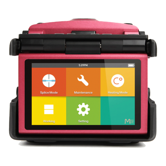
User’s Manual INNO Instrument, Inc. Chapter 3 - Basic Operation Turn On the Splicer Press the “ON/OFF” button on the top left of the front operating panel of the splicer. The READY screen of working menu (workbench) will be displayed after... -
Page 15: Adjust Lcd Backlight Brightness
User’s Manual INNO Instrument, Inc. Adjust LCD Backlight Brightness In the original operating interface (workbench), press the confirmation button then adjust LCD backlight brightness by tapping the two brightness icons on the LCD monitor, as the following picture shows: Note: The LCD monitor is a precise instrument of the splicer and it is produced in the factory under strict quality control. -
Page 16: How To Make A Splice
User’s Manual INNO Instrument, Inc. Important! You must ensure to keep the fibers clean. - Avoid putting them down on a dusty working surface - Avoid waving them around in the air - Check if the V-grooves are clean; if not, wipe them clean with cotton swab immersed into alcohol. -
Page 17: Splicing
User’s Manual INNO Instrument, Inc. If any defect exists in the optical fiber, please take out the optical fiber carefully and prepare it again. Note:The fibers are checked automatically when you press Splice button. The splicer automatically focuses the fibers and checks for damage or dust particles. - Page 18 User’s Manual INNO Instrument, Inc. Opening the heater lid position of splices Moving the fiber into heat oven Heat key Heating Indicator PAGE...
-
Page 19: Chapter 4 Splice Mode
INNO Instrument, Inc. Chapter 4 Splice Mode M9 fusion splicer has a concise and clear menu of splice mode, easy to be operated. Splice modes define arc currents, splice times as well as various parameters used when performing a splice. Therefore, it is essential to select the correct splice mode in accordance with the type of fiber you want to splice. -
Page 20: Selecting A Splice Mode
User’s Manual INNO Instrument, Inc. Selecting a Splice Mode ① Enter main menu. ② Click “Splice Mode” for entry. ③ Click “Select Splice Mode” before you can select the splice mode that you need. ④ A f t e r v i e w i n g a n d... -
Page 21: Steps Of Normal Splicing Program
User’s Manual INNO Instrument, Inc. Steps of Normal Splicing Program This section explains the steps involved in automatic splicing process and describes how various program parameters are related to this process. The normal splicing process can be divided into two sections; prefusion and fusion. -
Page 22: Parameters For Normal Splicing Process
User’s Manual INNO Instrument, Inc. Parameters for Normal Splicing Process Parameter Description A list of splice modes stored in the splicer database is displayed. Upon inputting the appropriate mode, the selected Template splice mode stored in database area is copied to a selected splice mode in user-programmable area. - Page 23 User’s Manual INNO Instrument, Inc. Parameter Description Set the end-face gap between the left and right fibers at the time of aligning and pre-fusion discharge. Sets the overlap amount of fibers at the fiber stuffing stage. Relatively small “Overlap” is recommended if “Pre- Overlape fuse power”...
-
Page 24: Chapter 5 Splice Option
User’s Manual INNO Instrument, Inc. Chapter 5 - Splice Option Splice Mode Setting Enter “Splice option” menu to select the options to change parameters. Parameter Description If “Auto start” is set to ON, splicing starts automatically Auto start as soon as the wind protector is closed. Fibers should be prepared and placed into the splicer in advance. - Page 25 User’s Manual INNO Instrument, Inc. Parameter Description Fiber Image on screen Pause1 Sets the method of displaying the fiber image on the screen during splicing operation. Align X : Enlarged display of X-axis image Pause2 Y : Enlarged display of Y-axis image...
-
Page 26: Chapter 6 Heater Mode
The INNO factory preset 3 kinds of mode, and the users can set the rest of the heating mode. Select the one best suited for the protection sleeve used. Each sleeve-heating mode included in M9 is optimized for a certain type of protection sleeve. These modes can be found in the database area for reference. -
Page 27: Edit Heater Mode
User’s Manual INNO Instrument, Inc. ③ Select one of the heating modes that you need. ④ After viewing and selecting the heating mode, you can press the button of “Reset” to go back to initial interface. Editing Heater Mode Sleeve-heating conditions stored in heating mode can be edited or changed. -
Page 28: Delete Heat Mode
User’s Manual INNO Instrument, Inc. ③ F i n a l l y , s e l e c t t h e parameters to edit the heating mode as needed. Delete Heat Mode ① Firstly enter “Heater mode” menu. -
Page 29: Chapter 7 Maintenance Menu
User’s Manual INNO Instrument, Inc. Chapter 7 - Maintenance Menu The splicer has a function to perform routine maintenance. This section describes how to use the maintenance menu. ① Enter “Maintenance menu” interface. ② Select the functions that you need to perform in the “Maintenance menu”... -
Page 30: Stabilize Electrodes
* Perform 20-cycle continuous discharge to stabilize the electrodes. Diagnostic Test M9 fusion splicer has a built-in diagnostic test feature that allows the user to perform a simple one step evaluation of splicer performance covering several different critical variables. Perform this function in case of splicer operation trouble. -
Page 31: Dust Check
User’s Manual INNO Instrument, Inc. Dust Check The splicer observes fibers through image processing. Dust or contaminants on the optical fibers, cameras’ lenses and wind protector mirrors will disturb normal observation of fibers and may result in improper splicing. This function checks the optical path for the presence or absence of contaminants and judges whether they cause trouble for fiber splicing. -
Page 32: Operation Procedure
User’s Manual INNO Instrument, Inc. Operation Procedure ① After you have selected “Arc Calibration” in maintenance menu, an image of “Arc Calibration” will be displayed on the screen. ② Set prepared fibers on the splicer, press “SET” button to begin ARC Calibration. -
Page 33: Chapter 8 Other Functions & Utilities
User’s Manual INNO Instrument, Inc. Chapter 8 - Other Functions & Utilities Data Storage This splicer stores up to 10,000 splicing results. Contents of data stored are different depending on splicing mode. Display Splice Record Splicing results stored in the memory can be displayed. Enter “Data Storage” Menu and Select “Display Splice Record”... -
Page 34: Monitor Position
User’s Manual INNO Instrument, Inc. Monitor Position The splicer is shipped from the factory with settings for the "Monitor Front" operation style. This can be changed to "Monitor Rear" operation style. When “Monitor Position” is changed, the direction of the four arrow keys is reversed. -
Page 35: Power Save Option
User’s Manual INNO Instrument, Inc. Power Save Option This function is important for power conservation. If the power saving function is not set during battery pack use, the number of splice cycles will decrease. (1) Insert a power unit and turn on the splicer. - Page 36 User’s Manual INNO Instrument, Inc. Appendix I High Splice loss: Cause and remedy Symptom Name Cause Remedy There’s dust in Fiber core Clean the V-grooves V-grooves and fiber axial offset and fiber hammer hammer There’s dust in Clean the V-grooves...
- Page 37 User’s Manual INNO Instrument, Inc. Some arc Adjust [Pre-fuse Power], Splicing line parameters not [Pre-fuse Time] or adequate [Overlap] Note :When different optical fibers (different diameters) or multi- mode fibers splicing, they will produce a vertical line which we call the "splicing lines" in a subsequent point, this does not affect splicing quality (splicing loss and splicing strength).
- Page 38 User’s Manual INNO Instrument, Inc. Appendix II Error Message List An error message may appear on the screen when using a splicer, the solution precisely as shown in the list below. If it is not possible to eliminate the problem, maybe some faults occur in the fusion splicer.
- Page 39 User’s Manual INNO Instrument, Inc. Error Message Cause Solution The fiber is not Fiber Clad Over located in the Adjust the fiber position and do “motor Limit Camera’s field of calibration” for maintenance. view. The fusion splicer is Carry out “motor calibration” for...
- Page 40 User’s Manual INNO Instrument, Inc. Error Message Cause Solution There’s dust or dirt Prepare the fiber (stripping, on the fiber surface cleaning, and cleaving) again. Dust or dirt is on the Execute the “Dust Check”. If dust lens or LEDs or dirt exists, clean the lenses or LEDs “Cleaning Arc...
- Page 41 User’s Manual INNO Instrument, Inc. Appendix III Questions and Troubleshooting The following gives the solution of some of the common problems for reference. If you cannot solve the problems, please contact the manufacturer directly. 1 .Power does not turn off when press “ON/OFF” button.
- Page 42 User’s Manual INNO Instrument, Inc. ★ Contact your nearest sales agency. 12. No arc power change after [Arc Calibration] ★ An internal factor is calibrated and adjusted for the specific arc power selected. The displayed arc power in each splice mode does not change.
- Page 43 The End Product specifications and models are subject to change without notice.
Need help?
Do you have a question about the M9 and is the answer not in the manual?
Questions and answers