
Subscribe to Our Youtube Channel
Related Manuals for Siemens NK8237 MP4.81-02


Summary of Contents for Siemens NK8237 MP4.81-02
- Page 1 NK8237 MP4.81-02 NK8237 IEC 60870-5-104 Gateway For Sinteso™ and Cerberus® PRO Fire Detection Systems Installation Configuration Commissioning Building Technologies A6V10854379_a_en 25.01.2019 CPS Fire Safety...
- Page 2 About this document Building Technologies A6V10854379_a_en CPS Fire Safety 25.01.2019...
-
Page 3: Table Of Contents
Table of contents About this document ......................5 Security disclaimer .................... 8 Safety regulations ....................9 Country-specific standards ................... 9 Assembly and installation ..................9 Commissioning and testing .................. 9 Disposal and recycling ..................10 Modifications to the system design and the products ........10 Data privacy and protection................ - Page 4 NW8204 diagnostic tool..................36 8.6.1 NW8204 hardware requirements ............36 8.6.2 NW8204 software requirements ............36 8.6.3 NW8204 installation ................36 Secure communication for web services ............37 Configuration ....................38 Configuration checklist ..................38 Configuring IP settings via NW8202 ..............39 Creating a new NK8237 IEC GW Composer project .........
-
Page 5: About This Document
Training program information including the Siemens intranet link ⚫ A complete list of all available DMS8000 documents ⚫ Instructions for how to obtain a document via the Siemens intranet using the ⚫ Siemens Asset Portal A map of relevant documents for each target audience group ⚫... - Page 6 4. In the list, select one or more documents and click the Download Assets icon. 5. After the download preparation completes (Background Process …), click Download and follow the instructions of your browser. For more information such as Siemens news and announcements, visit the STEP Web portal at: https://workspace.sbt.siemens.com/content/00001123/default.aspx...
- Page 7 For more information on creating flowcharts, printed material are indicated with an arrow see Flowcharts [→92]. and the page number, enclosed in brackets: [→92] Modification index Note: For versions more than four years old, please visit the Siemens Asset Portal. Version Date Notes A6V10854379_a_en 25.01.2019 NK8237 MP4.81-02.
-
Page 8: Security Disclaimer
About this document 1 Security disclaimer Products, solutions and services from Siemens include security functions to ensure the secure operation of building automation and control, fire safety, security management, and physical security systems. The security functions on these products, solutions and services are important components of a comprehensive security concept. -
Page 9: Safety Regulations
Country-specific standards Siemens Building Technologies products are developed and produced in compliance with the relevant international and European safety standards. This document provides warnings and recommendations specific to NK8000 products. -
Page 10: Disposal And Recycling
Modifications to the system design and the products Note: Modifications to a system or to individual products may cause faults or malfunctioning. Please request written approval from Siemens Building Technologies and from any relevant authorities concerning intended system modifications and system extensions. Data privacy and protection Make sure that the configuration of the system complies with local data privacy and protection regulations. -
Page 11: Introduction
Introduction Connectivity examples 3 Introduction The NK8000 family provides LAN/WAN adapter products for a safety and security network: NK822x series (no longer available, end of service: 31 December 2015) ⚫ NK823x Ethernet Ports series (NK8231, NK8232, NK8235) ⚫ NK8237 Modbus Gateway ⚫... -
Page 12: System Dimensions And Compatibility List
Introduction System dimensions and compatibility list 11.1Kernel update [→64] - Enhanced information in the Kernel Update System dimensions and compatibility list NK8237 Datasheet Please refer to (A6V10316240). Also, the latest information and NK8000 compatibility issues about the current software can be found in the Release Notes (A6V10062453). -
Page 13: System Limits
System limits 4 System limits The following describes the system limits for the NK8237 units. Fire control units The following control units are supported: FC2020 ⚫ FC2030 ⚫ FC2040 ⚫ FC2060 ⚫ FC2080 ⚫ FT2040 ⚫ FT2080 ⚫ FC722 ⚫ FC724 ⚫... - Page 14 System limits IEC 60870-5-104 hosts and system limits per each connected NK8237 unit IEC hosts Detectors and units per NK8237 1-4 IEC hosts Max. 10,000 detectors. ⚫ 16 FS20/FS720 units ⚫ Interaction capabilities Unlike the other NK8000 units, the NK8237 does not support interactions. I/O modules locally connected via I2C Unlike the other NK8000 units, the NK8237 does not support DF8000 I/O modules.
-
Page 15: Nk8000 Security
Structure and functions System dimensions and compatibility list 5 NK8000 Security To ensure the system security and prevent physical damages and attacks that may compromise the system integrity and confidentiality, make sure to install NK823x units according to the following criteria: NK823x units must be updated to latest Kernel and firmware versions. -
Page 16: Structure And Functions
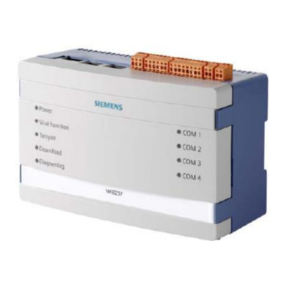
Structure and functions NK8237 hardware 6 Structure and functions NK8237 hardware The NK8237 is composed of an electronic board installed in a compact and robust plastic box. Note: NK8237 units with build state up to 01 are equipped with the NKM8001-A1 mainboard and NK8237 units with build state 10 or higher are equipped with the NKM8001-A2 mainboard. -
Page 17: Internal Dip Switches
Structure and functions NK8237 hardware Diagnostics (yellow LED) Internal interface diagnostics: : status OK. ⚫ Blinking (fast) : booting operating system after restart. ⚫ Blinking (1 flash) : missing or insufficient license. ⚫ Blinking (2 flashes) : trouble with the I C bus to I/O modules. -
Page 18: Internal Jumpers
Structure and functions NK8237 hardware 6.1.3 Internal jumpers X101 X102 X103 X104 X105 X111 Internal DIP switch and jumpers (NKM8001-A1 mainboard) Item Name Description S101 DIP-Switches Reset button Tamper switch X115 When closed, it disables the box tamper alarm. Building Technologies A6V10854379_a_en CPS Fire Safety 25.01.2019... -
Page 19: Serial Interfaces
Structure and functions NK8237 hardware X101 X102 X103 X104 X105 X111 Internal DIP switch and jumpers (NKM8001-A2 mainboard) Item Name Description S101 DIP-Switches Reset button Tamper switch X115 When closed, it disables the box tamper alarm. 6.1.4 Serial interfaces The NK8237.2 model is equipped with two serial lines available on the main board. The serial port can be configured as an RS232 interface using connector COM1 and COM2, or as an RS485 interface using connectors X104 and X105. -
Page 20: I2C Interface: Df8090 Power Supply Supervision
Structure and functions NK8237 hardware X101 onboard relay output. Signal Circuit Common X101 The input signals can be used for acquiring external power supply supervision lines, for example, to supervise the fire system power supply. Note that this is an alternative to the DF8090 power supply supervision (see I2C interface: DF8090 power supply supervision [➙... -
Page 21: Ethernet Interfaces
Structure and functions NK8237 hardware MAINS AC/DC LOW BATT BATT FUSE DF8090 front panel Item Description LEDs. C connector to I/O modules. See Figure NK8237 power supply (see NK8237 hardware installation [➙ 23]) for the power supply connections. 6.1.7 Ethernet interfaces The NK8237 main board is equipped with two Ethernet interfaces. -
Page 22: Usb Interface
Structure and functions NK8237 hardware 6.1.8 USB interface The NK8237 main board is equipped with a USB interface you can use to log data Network about network communications on a USB mass storage device (see the Connectivity Guide , document no. A6V10359485). 6.1.9 SD card The NK8237 mainboard is equipped with a 16 GB SD card. -
Page 23: Hardware Installation
Hardware installation NK8237 hardware installation 7 Hardware installation There are various possible installation scenarios. Namely: Installation of NK8237 in existing cabinets. ⚫ a. DIN-rail mounting (typical) in plastic housing. b. Mounting of the NK8237 board in the control unit housing using card holders (NKA8011-A1 required). - Page 24 Hardware installation NK8237 hardware installation Top view 321 654321 87654321 21 21 NK8237 electrical interfaces (top view) Item Name Description Ethernet 2 Ethernet 1 X101 1 output X102 3 inputs X103 Power supply X104 RS485 (in place of COM1) X105 RS485 (in place of COM2) Bottom view Serial RS232-interfaces (bottom view)
- Page 25 Hardware installation NK8237 hardware installation Power connections Note the dual power supply input for redundant solutions. X103 X104 X105 Power supply RS485-1 RS485-2 POWER SUPPLY DF8090 BATTERY 27Ah 12V Batt Vin = Voltage In Vout Vout = Voltage Out Batt = Battery NK8237 power connections Building Technologies A6V10854379_a_en...
- Page 26 Hardware installation NK8237 hardware installation WARNING There is a risk of explosion if the battery is replaced with an incorrect battery type. Use 27Ah 12V batteries. Dispose of the used battery at a recycling point in accordance with the local environmental standards and regulations. X103: Power Supply Power connections.
- Page 27 Hardware installation NK8237 hardware installation X102: Onboard I/O (Inputs) Onboard I/O (inputs). Assignment Input 1 (Mains failure) Input 2 (Battery fault) Input 3 (Power supply fault) Common + Val – Val COM 1, COM 2: RS232 Connectors RS232 lines are connected to 9pin D-Sub connectors, female type. RS232 connections.
-
Page 28: Ne8001 Housing Solution For Nk823X
Hardware installation NE8001 housing solution for NK823x NKA8011-A1 mounting plate NE8001 housing solution for NK823x The NE8001 cabinet offers a compact and convenient housing solution for the NK823x Ethernet Ports. The metallic cabinet allows for an easy wall-mounting. It includes a DIN rail and a prewired power supply for the NK823x unit and local I/O. 7.2.1 NE8001 hardware requirements Environmental requirements... - Page 29 Hardware installation NE8001 housing solution for NK823x WARNING Supporting wall must not be composed of inflammable material. 360 mm 415 mm Cabinet installation The VAC power supply wires (1.5 mm ) should be connected as illustrated in VAC power connection Figure WARNING Careful attention should be paid to the correct connections of VAC power lines.
- Page 30 Hardware installation NE8001 housing solution for NK823x 20 mm hole cut-outs Top view of NE8001 cabinet WARNING When entering the metallic frame of the cabinet, wires should be protected by a self-extinguishing plastic cord guard (UL94-V2 flammability rating). (Not provided in the supply). Wiring (1) –...
-
Page 31: Software Installation
Software installation Installation checklist 8 Software installation The software installation includes the following: Composer and basic tools for system configuration. ⚫ Additional tools: NW8202 (for IP configuration download), NW8204 (for ⚫ maintenance and diagnostic) IEC GW Add-on installation ⚫ Installation checklist Items needed for the installation DMS8000 DVD ⚫... -
Page 32: Installation Of Add-On Distribution Package
Software installation Installation of Add-on distribution package Installation of Add-on distribution package The NK8237 software for the IEC 60870-5-104 host support is distributed as an add-on package, to be installed on the stations including the Composer tool (client- only and FEP stations are therefore excluded) after the standard Composer Setup. The package is named MM8000 MP4.81 - Addon N.10 (IEC GW - V.1.01) - CD and is made up by an installation kit of a few files. -
Page 33: Removing The Add-On Module
Software installation Installation of Add-on distribution package 8.3.1.2 Multiple add-ons installations In general, it is possible to install multiple add-on packages and benefit of their combined functionalities. However, specific incompatibilities might exist. For any possible issues, check the documentation of the add-on modules that must be installed. -
Page 34: Launching Composer
Software installation Launching Composer Launching Composer Do one of the following: ⚫ – Launch Composer through the Start menu: Start > Programs > DMS8000 > Composer. – Launch Composer by selecting the shortcut icon on your desktop, if available. When you start Composer for the first time, the following window displays: Composer server selection Note: To see this window every time you start Composer, deselect the Hide this dialog check box. -
Page 35: Nw8202 Ip Configuration Download Tool
Software installation NW8202 IP configuration download tool Projects Management window The Project Market Package version is indicated in parentheses. Note 1: To access the Projects Management window from an open project, select Tools > Projects Management from the Main menu. Note 2: To return to the project, double-click on it in the Projects Management tree or select it and then click Open icon NW8202 IP configuration download tool... -
Page 36: Nw8204 Diagnostic Tool
Software installation NW8204 diagnostic tool On a DMS8000 system, you launch NW8202 by selecting the NW8202.exe file from the following directory: <InstallationDir> > Utilities > NW8202 The default installation folder is: C:\Program files\DMS8000 (assuming an English version of Windows). To install the NW8202 tool on a service PC, do the following: 1. -
Page 37: Secure Communication For Web Services
Internet websites. Several certificate authorities can provide an SSL certificate for a moderate annual charge (in case of issues, contact your local IT Manager or the Siemens customer support center). Configure the browser of your client systems to trust the self-signed certificate. -
Page 38: Configuration
Configuration Configuration checklist 9 Configuration The following figure provides an overview of the configuration workflow. Basically, there are three configuration steps: 1. Configure the fire detection with Sinteso Works (or Cerberus-Engineering-Tool) and download the fire system. Then, export the configuration to SiB-X format. 2. -
Page 39: Configuring Ip Settings Via Nw8202
Configuration Configuring IP settings via NW8202 Configuration workflow 1. If necessary, configure the NK8237 IP address(es) via the NW8202 [➙ 39]. 2. In Composer, create [➙ 41] the NK8237 project. 3. Create [➙ 43] the IEC system. 4. Create [➙ 44] the NK8237 gateway. 5. - Page 40 Configuration Configuring IP settings via NW8202 NW8202 IP configuration download tool 7. Click Download. The Download Procedure window displays. 8. Follow the instructions. Note: The network cable must be connected to the NK8237 Ethernet port 1 or 2 depending on the IP address set in the service PC (to locate the correct Ethernet port, see Ethernet interfaces [➙...
-
Page 41: Creating A New Nk8237 Iec Gw Composer Project
Configuration Creating a new NK8237 IEC GW Composer project Creating a new NK8237 IEC GW Composer project You can create a new NK8237 IEC GW project using a predefined template, NK8237-IEC_GW.bak, which is provided with the MM8000 MP4.81 - Addon N.10 (IEC GW - V.1.01) - CD. - Page 42 Configuration Creating a new NK8237 IEC GW Composer project Starting a new project: by restoring a saved Composer project backup 1. In the Projects Management window, click the Restore button. The Restore window displays. 2. In the line corresponding with File to be restored, click the Browse button. ...
-
Page 43: Creating The Iec System(S)
Configuration Creating the IEC system(s) You have to configure the system starting from the section Creating the IEC system(s) [➙ 43]. Stand-alone (MM8000) or Stand-alone Station (MK8000). A new empty project ⚫ is created. This kind of project is not suitable for configuring an NK8237 IEC Note: Do not use an MM8000 or MK8000 empty project for configuring the NK8237 IEC GW, which cannot be used in MM8000 or MK8000 configurations. -
Page 44: Creating The Nk8237 Gateway
Configuration Creating the NK8237 Gateway Creating the NK8237 Gateway This configuration task is carried out in Composer on a project created for the NK8237 gateway starting from an empty template to which an IEC system has been added. 9.5.1 NK8237 creation procedure Adding the folder for the NK8237 gateway 1. - Page 45 Configuration Creating the NK8237 Gateway – If NAT (Network Address Translation) is used on the network, enable it and enter the external IP address (NAT address) of the NK8237. Configuring the routing table 1. Select the NK823x node. 2. In the Routing tab, click the Add button to add a new route. 3.
- Page 46 Configuration Creating the NK8237 Gateway Routing table configuration (from MP4.81-02, the Enable dynamic routing (OSPF) option is no longer supported) Checking the routing table The configuration has been downloaded to the NK8237 unit. 1. Select the NK8237 node. 2. In the Routing tab, click the Get Info button to upload the routing configuration from the selected NK8237 unit.
- Page 47 Configuration Creating the NK8237 Gateway Routing table upload and check (from MP4.81-02, the Enable dynamic routing (OSPF) option is no longer supported) Configuring the IEC LAN connectivity 1. Select the NK8237 node and expand the subtree. 2. Select the Protocols node. 3.
-
Page 48: Configuring The Fire Network
Configuration Configuring the Fire network Configuring the Fire network This configuration task is carried out in Composer. The communication between FS20/FS720 and the NK8237 IEC Gateway is based on BACnet/IP. The following rules apply: The FS20/FS720 and NK8237 units must share the same BACnet Virtual ⚫... - Page 49 Configuration Configuring the Fire network Selecting FC20 subsystems to import 4. Select the stations to import. Select All to import the structure of the entire fire system, or select the individual stations that you want to import. Then, click OK. ...
- Page 50 Configuration Configuring the Fire network Example of FS20 Station BACnet settings Setting the FC20xx/FC72x Ack/Reset mode Acknowledgement and reset commands can only be set as general actions in the IEC Gateway. This means that the commands apply to all the pending events of the affected control unit.
-
Page 51: Nk823X Bacnet Protocol
Configuration Configuring the Fire network 9.6.2 NK823x BACnet Protocol The fire system connection to the NK8237 IEC Gateway makes use of the BACnet protocol over IP. In the BACnet/IP communication with the fire units, the NK8237 IEC Gateway acts as a BACnet client. The NK823x configuration in Composer includes the definition of the IP addressing and BACnet/IP connectivity. - Page 52 Configuration Configuring the Fire network – Destination and Netmask, addressing a subnet (recommended) or a single address according to IP addressing rules. For example, Destination = 192.168.2.0 and Netmask = 255.255.255.0 define any address in the range 192.168.2.1 through 254. Instead, Destination = 192.168.2.10 and Netmask = 255.255.255.0 define the single IP address 192.168.2.10.
-
Page 53: Fs20 Bacnet Connection To Nk823X
Configuration Configuring the Fire network – Remote BBMD Port Number (must match the UDP port configuration configured in the unit acting as BBMD; default value is 47808 or BAC0 hex). – Time-To-Live (default is 1800, 0 means permanent; in general, it must not be changed). -
Page 54: Customising The Iec Interface
Configuration Customising the IEC Interface Customising the IEC Interface In the IEC Master node, a number of configuration settings can be customised relevant to the general NK8237 gateway parameters, as well as to the address of IEC devices and data tables. Note: The NK8237 handles a number of data tables to implement the IEC communication at application level. -
Page 55: General Parameters Configuration Procedures
Configuration Customising the IEC Interface – Receive date and time synchronization from the IEC master station. – Acquire date and time from the FS20 system every day at a given time – Acquire date and time from a Network Time Protocol (NTP) server (configuration in NK823x Node tab). -
Page 56: Iec Addresses
Configuration Customising the IEC Interface Note: Do not select the Power Supply Supervision option for the onboard inputs even if the signals are used for this supervision purpose. Instead, create the 3 generic inputs and then customise the description texts appropriately. The Power Supply Supervision configuration option, which globally defines the input signals, is currently not supported by NK8237. -
Page 57: Export And Re-Import Of The Iec Address Map
Configuration Configuring the relay output Configuring the table base address 1. Select the IEC Master node. 2. Select the Host tab. 3. In the Device Base Address section, modify the Object Base Address values as needed. Make sure to define a consistent address scheme and avoid any conflicts. -
Page 58: Downloading The Nk8237
Configuration Downloading the NK8237 1. Select the NK8237 node and expand the subtree. 2. In the toolbar on the left, select the Onboard I/O icon A new Onboard I/O node appears. 3. Select the new I/O Onboard node. 4. In the toolbar on the left, select the Relay Output icon ... -
Page 59: Verifying The Connection To The Nk8237 Unit
Configuration Downloading the NK8237 To enable the secure download or to set the FTP mode, select the related option in the Node tab of the NK8237 node. If enabled, the secure download makes use of the TCP port 20500 instead of the ports 20 and 21 required by FTP. Note: For IT security reasons we recommend always using the secure download mode. - Page 60 Configuration Downloading the NK8237 Note: You can check the current firmware version on the Tools tab of the NK8237 node by pressing the Read All button. 9.9.3.1 DMS8000 network infrastructure configuration Adding the download communication driver 1. Select the main node of the project. 2.
- Page 61 Configuration Downloading the NK8237 8. Drag-and-drop the selection to the NS8011 BACnet Driver node. A link node is created under the driver node. 9.9.3.2 NK8237 firmware download Downloading a firmware update 1. Select the Download tab of the NS8011 Driver node. 2.
- Page 62 Configuration Downloading the NK8237 – Free RAM available (bytes) – Kernel Version: Linux version and release date – Factory Burning Date (when the product burned-in) – EEPROM information: event logging and counters – Log Status: active, inactive, active after on-the-fly configuration changes have been set (by NW8204 tool) –...
-
Page 63: System Test
System test 10 System test General checks on NK8237 The power supply, vital functions, and diagnostic state of NK8237 can be checked on the front panel. For more advanced diagnostics, see Maintenance and diagnostics [➙ 64]. Checking the IEC connection A complete check can be done from the IEC host. -
Page 64: Maintenance And Diagnostics
Maintenance and diagnostics Kernel update 11 Maintenance and diagnostics 11.1 Kernel update The NK8237 Kernel is the main component of the operating system, which acts as a bridge between the application and the hardware level. In certain conditions, it may be necessary to update the Kernel, following specific instructions of the technical support. -
Page 65: The Nw8204 Diagnostic Tool
Maintenance and diagnostics The NW8204 diagnostic tool It verifies whether an SD card is inserted into the NK823x. If the SD card is not ⚫ inserted, you can abort the update and insert the SD card, or complete the update The Kernel update may take several minutes. - Page 66 Maintenance and diagnostics The NW8204 diagnostic tool NW8204 window (installed GUI) 2. Insert the NK IP Address. Note: Inserting an incorrect IP address causes the following window to display. If you are notified by this message, click OK and enter again the IP Address. If you want to enter the NK8237 default IP address 192.168.9.41, you can use the menu Set Default IP Address instead of manually enter it.
- Page 67 Maintenance and diagnostics The NW8204 diagnostic tool NW8204 window with open connection (installed GUI) Item Name Description Change User Select to display the user login window (see step 1). About Displays the version of the NW8204 tool. Local File Browse for a local copy of DIAGNO.LOG or EEPROM.LOG to analyse/troubleshoot a remote NK82xx (admin user only).
-
Page 68: File Commands
Maintenance and diagnostics The NW8204 diagnostic tool 11.2.2 File commands These commands are meant for remote technical maintenance and diagnostics of the NK8237 units. The commands apply to the file selection active in the list on the left of the screen. Download file Transfer the selected file to the NK8237. - Page 69 Maintenance and diagnostics The NW8204 diagnostic tool Set Date Time Open a window for setting date and time and download the new settings to the RTC of NK8237. Note: This function is only available when logged in as user “admin”. Setting date and time NK Vitality Open a window that display the current status of the NK8237 point image.
- Page 70 Maintenance and diagnostics The NW8204 diagnostic tool Click this button to display the Port Number dialog box: Port number request A possible port number to check is 2404 (IEC). Click OK to check the port number. At that point, the associated field displays the type of information found (for example, Last IP connected) and you can to use the field arrow controls to display the current IP address.
-
Page 71: Uploading Diagnostic Files
Maintenance and diagnostics The NW8204 diagnostic tool Read the NK8237 firewall status: Enabled, Disabled. Read Routing Status Read the NK8237 routing status: Enabled, Disabled. 11.2.4 Uploading diagnostic files Diagnostic file purposes The purpose of these files is to record messages of what occurred to NK8237 to make it easier to determine any issues, or if something important happened. - Page 72 Maintenance and diagnostics The NW8204 diagnostic tool EV_EEPROM_NEW_DATE_TIME Date and time changed over delta threshold EV_EEPROM_RESET Reset command EV_EEPROM_EMERGENCY Restart in emergency mode EV_EEPROM_FTP_SESSION FTP session opened EV_EEPROM_CONFIG_CHANGE Configuration file changed EV_EEPROM_SW_CHANGE Software version changed EV_EEPROM_CPU_CHANGE CPU changed EV_EEPROM_ETH_PNP_UPDAT Ethernet EEPROM update EV_EEPROM_ETH_PNP_ERROR Ethernet EEPROM update failed EV_EEPROM_DLL_LOAD_FAILED DLL load failure...
-
Page 73: Using Log Files
Maintenance and diagnostics The NW8204 diagnostic tool The browse window opens. 3. Choose the location where you want to store the file(s). Then, click Save. 4. Click Close Connection. If you do not close the connection, you will be automatically timed out in five minutes. - Page 74 Maintenance and diagnostics The NW8204 diagnostic tool Configuring the log upload Uploading log data Note: If the data upload procedure seems to take too long to be accomplished, you can abort the procedure by clicking the Abort Log Upload button. Note: The log file can be imported as CSV file to a spreadsheet application to be analyzed by expert users (Technical Support).
- Page 75 Maintenance and diagnostics The NW8204 diagnostic tool WARNING Removing the USB key while the logging is enabled (without using the Safely Remove command) may cause the unit to restart or block (a manual restart is then needed). Always use the Safely Remove command before removing the USB memory device! Note: If you use the SD card as default log storage, removing an USB mass storage device temporarily set as the active log storage does not automatically...
-
Page 76: Correcting Communication Failures
Maintenance and diagnostics Correcting communication failures Configuring logging function on the fly Note: The reset of the unit results in restoring the original logging configuration saved in Composer. 11.3 Correcting communication failures 11.3.1 IEC communication problems Communication faults on the IEC may depend on different causes. The problem can occur in the NK8237 unit or in the connections. -
Page 77: Fire Systems Communication Problems
Maintenance and diagnostics Correcting communication failures Command Meaning Shows comprehensive information about the local PC’s IP configuration (for ipconfig /all example, the IP address) Lets you check the communication with an IP network participant (“n.n.n.n” is ping n.n.n.n the IP address to check) Lets you continuously check the communication with an IP network ping n.n.n.n –t participant (“n.n.n.n”... -
Page 78: Control Unit Does Not Respond
Maintenance and diagnostics Correcting communication failures 11.3.4 Control unit does not respond When adding and configuring an NK8237 node, verify that you have the correct protocol, Local address and Baud rate, and that the data link is up (blinking red and green). -
Page 79: Secure Operation Requirements
Compliance with local regulations must be addressed. This can concern paper listings as well as tapes and memory support. For further information on general security issues regarding Siemens products, please refer to the internal documentation and procedures on this subject. - Page 80 Issued by © Siemens Switzerland Ltd, 2019 Siemens Switzerland Ltd Technical specifications and availability subject to change without notice. Building Technologies Division International Headquarters Theilerstrasse 1a CH-6300 Zug Tel. +41 41-724 24 24 www.siemens.com/buildingtechnologies Document ID A6V10854379_a_en DMS8000 Technical Material Edition 25.01.2019...
Need help?
Do you have a question about the NK8237 MP4.81-02 and is the answer not in the manual?
Questions and answers