Siemens SIMATIC HMI Series Operating Instructions Manual
Mobile panels 2nd generation
Hide thumbs
Also See for SIMATIC HMI Series:
- System manual (226 pages) ,
- Operating instructions manual (130 pages) ,
- Getting started (52 pages)
Table of Contents
Advertisement
Quick Links
SIMATIC HMI
HMI devices
Mobile Panels 2nd Generation
Operating Instructions
09/2018
A5E33876626-AC
___________________
Preface
___________________
Overview
___________________
Safety instructions
Installing system
___________________
components
___________________
Handling the Mobile Panel
Parameterizing the Mobile
___________________
Panel
___________________
Configuring the Mobile Panel
___________________
Commissioning a project
___________________
Operating a project
___________________
Fail-safe operation
___________________
Maintenance and care
___________________
Technical specifications
___________________
Technical Support
___________________
Markings and symbols
___________________
List of abbreviations
1
2
3
4
5
6
7
8
9
10
11
A
B
C
Advertisement
Table of Contents

Subscribe to Our Youtube Channel
Related Manuals for Siemens SIMATIC HMI Series


Summary of Contents for Siemens SIMATIC HMI Series
- Page 1 ___________________ Preface ___________________ Overview ___________________ SIMATIC HMI Safety instructions Installing system ___________________ components HMI devices Mobile Panels 2nd Generation ___________________ Handling the Mobile Panel Parameterizing the Mobile ___________________ Panel Operating Instructions ___________________ Configuring the Mobile Panel ___________________ Commissioning a project ___________________ Operating a project ___________________...
-
Page 2: Legal Information
Note the following: WARNING Siemens products may only be used for the applications described in the catalog and in the relevant technical documentation. If products and components from other manufacturers are used, these must be recommended or approved by Siemens. Proper transport, storage, installation, assembly, commissioning, operation and maintenance are required to ensure that the products operate safely and without any problems. -
Page 3: Preface
Preface Purpose of the operating instructions These operating instructions contain information on place of use, transport, storage, mounting, use and maintenance of the device. These operating instructions are intended for: ● Users ● Commissioning engineers ● Maintenance personnel You can find more information such as operating instructions, examples and reference information in the information system of the TIA Portal or through online support. - Page 4 Preface The document applies in conjunction with the software listed in "Software required (Page 24)". Note This document is part of the Mobile Panel system, connecting cable and connection box, and is also required for repeat commissioning. Keep all supplied and supplementary documentation for the entire service life of the Mobile Panel.
- Page 5 Preface Naming conventions Term Applies to Control cabinet Mounted cabinet, enclosure, terminal box, panel, control panel Plant System, machining center, one or more machines F-system Fail-safe automation system with fail-safe Mobile Panel Connection box Connection box compact • Connection box standard •...
- Page 6 Preface Figures This document contains figures of the devices described. The figures can deviate from the particularities of the delivered device. Picture components are marked with black position numbers on a white background ① ② ③ , etc. Steps in the figures are identified with white process numbers on a black background according to the sequence in which they have to be executed: , ...
-
Page 7: Table Of Contents
Table of contents Preface ..............................3 Overview............................... 13 Product overview ........................13 Design of the Mobile Panels ....................14 KTP Mobile connecting cable ....................17 Connection boxes ........................18 Scope of delivery ........................20 Accessories ..........................21 1.6.1 KTP Mobile wall-mounting bracket ..................21 1.6.2 Fail-safe KTP Mobile spare key .................... - Page 8 Table of contents Attaching the KTP Mobile wall-mounting bracket ..............47 3.4.1 Assembling the KTP Mobile wall-mounting bracket ............... 47 3.4.2 Mounting position and clearance ................... 48 3.4.3 Fasteneing the KTP Mobile wall-mounting bracket ............... 50 Connecting the Mobile Panel ....................51 3.5.1 Connection information ......................
- Page 9 Table of contents Configuring operation......................96 5.7.1 Changing display brightness ....................96 5.7.2 Configuring the screen keyboard .................... 97 5.7.3 Setting the character repeat rate of the screen keyboard ............98 5.7.4 Setting the double-click ......................99 5.7.5 Calibrating the touch screen ....................100 5.7.6 Restarting the HMI device ....................
- Page 10 Table of contents 5.15.6 Editing IP addresses and communication connections ............159 5.15.6.1 Overview ..........................159 5.15.6.2 Assigning IP address and device name ................160 5.15.6.3 Configuring a communication connection ................162 Configuring the Mobile Panel ....................... 165 Configuration in WinCC ....................... 167 6.1.1 Adding a controller to the project ..................
- Page 11 Table of contents Direct keys ..........................205 Setting the project language ....................205 Entering and modifying the value, date and time ..............206 Displaying infotext ......................... 207 Closing the project ........................ 208 Fail-safe operation ..........................209 Connecting the connecting cable ..................209 Unplugging the connecting cable ..................
- Page 12 Table of contents 11.8 Technical specifications ....................... 233 11.8.1 Mobile Panel ........................233 11.8.2 Connecting cable ......................... 235 11.8.3 Connection boxes ........................ 236 11.8.4 Power consumption specifications ..................238 11.8.5 Reaction times and safety characteristics for fail-safe operation ........239 11.8.6 Specification of cables to be used ..................
-
Page 13: Overview
Overview Product overview The second generation of SIMATIC HMI Mobile Panels offers direct mobile operation and monitoring of the production process. The Mobile Panels 2nd Generation system consists of a Mobile Panel, connection box and connecting cable. The Mobile Panels 2nd Generation is available with display sizes 4", 7" and 9" widescreen. The figure below shows a fail-safe Mobile Panel with a 7"... -
Page 14: Design Of The Mobile Panels
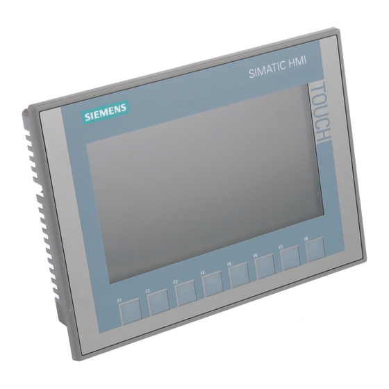
● High impact resistance ● High chemical resistance to operating and cleaning agents (http://support.automation.siemens.com/WW/view/en/39718396). The enclosure type protects the emergency stop / stop button. Two protective bumpers to prevent damage to the emergency stop / stop button during a fall of the HMI device. - Page 15 Overview 1.2 Design of the Mobile Panels Front and side views The figures below show an example of the design of the fail-safe HMI device, KTP900F Mobile. The other HMI devices of the type KTP Mobile are constructed similarly. ① Keyswitch, only for KTP700F Mobile and KTP900F Mobile ②...
- Page 16 Overview 1.2 Design of the Mobile Panels Rear view and interfaces The figure below shows an example of the design of the fail-safe HMI device, KTP900F Mobile. The other HMI devices of the type KTP Mobile are constructed similarly. ① ⑤...
-
Page 17: Ktp Mobile Connecting Cable
Overview 1.3 KTP Mobile connecting cable KTP Mobile connecting cable You connect the Mobile Panel to the connection box using the rugged connecting cable. The tensile and flexural strength of the connecting cable is geared toward the actual usage conditions. Functions of the connecting cable: ●... -
Page 18: Connection Boxes
Overview 1.4 Connection boxes Connection boxes The connection boxes are available in the following versions: ● Connection box compact, article number 6AV2125-2AE03-0AX0 ● Connection box standard, article number 6AV2125-2AE13-0AX0 ● Connection box advanced, article number 6AV2125-2AE23-0AX0 Connection box compact The figure below shows the connection box compact. ①... - Page 19 Overview 1.4 Connection boxes Connection box standard and connection box advanced The figure below shows the connection box standard or the connection box advanced. The connection box advanced also features: ● Real-time Ethernet ● F-signal transmission ① LED display ② Screw glands for the data cables ③...
-
Page 20: Scope Of Delivery
● LED flashes green or amber: Link established, data transfer in progress You can find information about other possible LED states in the following document: Operating instructions "SCALANCE X-200" (https://support.industry.siemens.com/cs/ww/en/view/102051962) See also Connecting the connection box (Page 59) Scope of delivery This section describes the system components in the scope of delivery that you need for operating a Mobile Panel 2nd Generation. -
Page 21: Accessories
Accessories are not included in the scope of delivery but can be ordered from the following address: HMI accessories (https://mall.industry.siemens.com/mall/en/WW/Catalog/Products/10144445) In the Industry Mall you can find the following accessories for the HMI devices of type KTP Mobile, for example: ●... -
Page 22: Fail-Safe Ktp Mobile Spare Key
Panel. Use the following storage media: ● SIMATIC HMI Memory Card Siemens AG has approved the use of SD memory cards in the Mobile Panel. ● USB flash drive The USB flash drive must be suitable for industrial applications. The storage medium is inserted in the port on the left of the device. -
Page 23: Sirius Safety Relays
● SIRIUS safety relay, advanced, electronic output article number 3SK1122-1AB40 You can find the complete portfolio of the SIRIUS 3SK safety relays on the Internet (http://www.siemens.com/product?3SK). Note Evaluation of the safety-related operator controls via F-DI modules Instead of a SIRIUS safety relay, F-DI modules can be used for the evaluation. -
Page 24: Software Required
This section defines terms relating to fail-safe operation with a fail-safe HMI device. You can find additional information on the topic of "Safety" in the following document: "SIMATIC Safety - Configuring and Programming" programming and operating manual (http://support.automation.siemens.com/WW/view/en/54110126) Mobile Panels 2nd Generation Operating Instructions, 09/2018, A5E33876626-AC... - Page 25 Overview 1.8 Terms for fail-safe operation Fail-safe automation system, F system A fail-safe automation system is required in a plant with high safety requirements. An F-system is characterized by the following features: ● Safety-related shutdown response of the system after the triggering of a stop or emergency stop via a safety-related operator control.
- Page 26 Overview 1.8 Terms for fail-safe operation Safety-related operator controls A fail-safe Mobile Panel comes equipped with the two safety-related operator controls "Emergency stop / stop button" and "Acknowledgment button". All other operator controls are not safety-related operator controls. Fail-safe operation In a hardwired or PROFIsafe-based F-system, you operate the plant or a plant section in fail- safe mode.
- Page 27 Overview 1.8 Terms for fail-safe operation Safety-related operating mode In fail-safe mode, you can use the HMI device in combination with a connection box in one of the following operating modes: ● Stop button evaluated by safety relay This operating mode is intended for a hardwired F-system. The signals of the safety- related operator controls are wired to a safety relay.
-
Page 28: Organizational Measures
Overview 1.9 Organizational measures Mobile Panel logoff Before disconnecting the fail-safe HMI device from a connection box, you must log off the HMI device using an appropriate operator control of the safety program or close the current project. Logoff must be confirmed in a dialog. When you log off, the HMI device is removed from PROFIsafe communication. -
Page 29: Mobile Panel And Connection Box Compatibility
Overview 1.10 Mobile Panel and connection box compatibility F-systems The table below shows the F-systems that can be configured or installed for a given connection box. Requirement is that you are using a fail-safe Mobile Panel. Connection box PROFIsafe- Hardwired F-system, no Hardwired F-system with based F-system emergency stop/stop bypass... - Page 30 Overview 1.10 Mobile Panel and connection box compatibility Compatibility of Mobile Panels 1st Generation – connection boxes of the Mobile Panel 2nd Generation You can use the connection box compact, the connection box standard and the connection box advanced with the following predecessor devices: ●...
-
Page 31: Safety Instructions
Safety instructions General safety instructions The device is designed for operation in industrial areas for operator control and monitoring of plant processes. WARNING Personal injury or material damage due to non-compliance with safety regulations Failure to exactly comply with the safety regulations and procedures in this document can result in hazards and disable safety functions. - Page 32 Safety instructions 2.1 General safety instructions WARNING Programming startup protection in the safety program At a STOP/RUN transition of an F-CPU, the standard user program starts up as usual. When the safety program starts up, all FDBs are initialized with values from the load memory, same as during a cold restart.
- Page 33 Take appropriate protection measures to prevent physical injury or material damage. You can find additional information in the following document:Configuration manual "SCALANCE X-200" (https://support.industry.siemens.com/cs/ww/de/view/109476763) Note Observe the Operational Safety and Product Monitoring newsletter. Plants with safety-related characteristics are subject to special requirements for operational safety on the part of the operator.
- Page 34 Safety instructions 2.1 General safety instructions Safety when working in and on electrical systems Work in or on electrical systems may only be carried out by authorized persons. The following safety regulations apply for the prevention of electric shock and electrocution: 1.
- Page 35 In order to protect plants, systems, machines and networks against cyber threats, it is necessary to implement – and continuously maintain – a holistic, state-of-the-art industrial security concept. Siemens’ products and solutions constitute one element of such a concept. Customers are responsible for preventing unauthorized access to their plants, systems, machines and networks.
-
Page 36: Security Management For Hmi Devices
Siemens’ products and solutions undergo continuous development to make them more secure. Siemens strongly recommends that product updates are applied as soon as they are available and that the latest product versions are used. Use of product versions that are no longer supported, and failure to apply latest updates may increase customer’s exposure to... -
Page 37: Notes About Usage
Safety instructions 2.4 Notes about usage Notes about usage NOTICE HMI device approved for indoor use only The HMI device may be damaged if operated outdoors. Operate the HMI device indoors only. Note Operate the device only in a normal atmospheric environment The technical characteristics of the device described in the operating instructions are guaranteed if you operate the device in normal ambient air conditions with usual air composition. -
Page 38: Risk Assessment Of The Plant
"Fail-safe operation". Take the plant configuration as a whole into consideration in the risk assessment and not just the individual areas. Additional information on risk assessment and risk reduction is available at: "Safety Technology in SIMATIC S7" system manual (http://support.automation.siemens.com/WW/view/en/12490443) Mobile Panels 2nd Generation Operating Instructions, 09/2018, A5E33876626-AC... -
Page 39: Important Information On Emergency Stop / Stop Button
Safety instructions 2.6 Important information on emergency stop / stop button Important information on emergency stop / stop button WARNING Emergency stop / stop button disabled when HMI device is not connected When the fail-safe Mobile Panel is not connected to the connection box, an emergency stop or stop cannot be triggered with the HMI device. -
Page 40: Important Notes For The Enabling Mechanism
Safety instructions 2.7 Important notes for the enabling mechanism NOTICE Versions of the connection box If you install connection boxes with and without emergency stop / stop bypass in your fail- safe automation system, there is a risk that an accidental shutdown is triggered when replugging an HMI device. - Page 41 Safety instructions 2.7 Important notes for the enabling mechanism Safety instructions WARNING Injury or material damage Enabling buttons should only be used when the following applies for the person activating the enabling button: • The person can see the danger zone. •...
- Page 42 Safety instructions 2.7 Important notes for the enabling mechanism Note Information on discrepancy errors The enabling button has two channels. Both channels must be activated at the same time for the "enable" and "panic" switch positions. If only one channel is activated, a discrepancy error occurs and "enabling"...
-
Page 43: Installing System Components
"Scope of delivery (Page 20)". Note Do not install parts damaged during shipment. In the case of damaged parts, contact your Siemens representative. See section "Service and support (Page 268)". Mounting the connection box compact 3.2.1 Mounting position, mounting cutout and clearance... - Page 44 Installing system components 3.2 Mounting the connection box compact The following illustration shows the dimensions for the mounting cut-out, all dimensions in mm: Clearance The connection box is self-ventilated. To ensure self ventilation in the control cabinet and be able to connect the connecting cable without any problems, you need the clearance indicated in the figures below, all dimensions in mm: Note that in addition to the mounting depth of the connection box, a rear clearance is re-...
-
Page 45: Fastening The Connection Box Compact
Installing system components 3.3 Installing the connection box standard and connection box advanced 3.2.2 Fastening the connection box compact Read the instructions for work in and on electrical systems and on ESD in "General safety instructions (Page 31)". Requirement ● 4 mounting clips ●... -
Page 46: Fastening The Connection Box Standard And Connection Box Advanced
Installing system components 3.3 Installing the connection box standard and connection box advanced Clearance To ensure unhindered access to the interfaces, the clearance indicated in the figure below is required: 3.3.2 Fastening the connection box standard and connection box advanced This section describes the mounting of the Anschuss box standard and the connection box advanced on a flat metal surface, such as a control cabinet wall. -
Page 47: Attaching The Ktp Mobile Wall-Mounting Bracket
Installing system components 3.4 Attaching the KTP Mobile wall-mounting bracket Attaching the KTP Mobile wall-mounting bracket 3.4.1 Assembling the KTP Mobile wall-mounting bracket The scope of supply for the wall-mounting bracket includes the following components: ● Wall-mounting bracket ● Safety bar for the HMI device ●... -
Page 48: Mounting Position And Clearance
Installing system components 3.4 Attaching the KTP Mobile wall-mounting bracket 3.4.2 Mounting position and clearance Mounting position The KTP Mobile wall-mounting bracket is designed for vertical walls or one of the following types of enclosures: ● Mounting cabinets ● Control cabinets ●... - Page 49 Installing system components 3.4 Attaching the KTP Mobile wall-mounting bracket Clearance Consider the space required for the connecting cable used and the height that the HMI device extends up and over the wall-mounting bracket. The figure below shows the minimum clearance required around the wall bracket. ①...
-
Page 50: Fasteneing The Ktp Mobile Wall-Mounting Bracket
Installing system components 3.4 Attaching the KTP Mobile wall-mounting bracket 3.4.3 Fasteneing the KTP Mobile wall-mounting bracket Requirement The requirements refer to the installation of the wall-mounting bracket to a control cabinet. ● A level bolting surface ● 3 M5 bolts and a suitable screwdriver ●... -
Page 51: Connecting The Mobile Panel
Installing system components 3.5 Connecting the Mobile Panel Connecting the Mobile Panel 3.5.1 Connection information The Mobile Panel is supplied with an open terminal compartment. During commissioning, you will be working with an open terminal compartment when replacing the SD card or when replacing the connecting cable. - Page 52 Installing system components 3.5 Connecting the Mobile Panel Note Use only a SIMATIC HMI Memory Card Use only a SIMATIC HMI Memory Card with the Mobile Panel. NOTICE Unsuitable tools may damage the Mobile Panel To avoid damaging the motherboard of the Mobile Panel, insert or remove the SD memory card with an appropriate tool made of plastic.
-
Page 53: Connecting The Mobile Panel Connecting Cable
Installing system components 3.5 Connecting the Mobile Panel 3.5.3 Connecting the Mobile Panel connecting cable The connecting cable is a system component and is required for the operation of the Mobile Panel. Use a cable labeled "Connecting cable KTP Mobile". Note If you use an SD memory card, you must insert the SD memory card before installing the connecting cable. -
Page 54: Connecting A Configuring Pc
Installing system components 3.5 Connecting the Mobile Panel 3.5.4 Connecting a Configuring PC You can transfer the following data between the HMI device and a configuration PC: ● Project ● HMI device image ● Additional project data Procedure 1. Connect the configuration PC to an Ethernet network. 2. -
Page 55: Replacing The Connecting Cable
Installing system components 3.5 Connecting the Mobile Panel 3.5.5 Replacing the connecting cable Requirement ● The connecting cable is unplugged from the connection box. ● You have taken precautions to protect your device, see section "Connection information (Page 51)". ● One torque screwdriver with cross-tip insert size 2 Procedure Open 1. - Page 56 Installing system components 3.5 Connecting the Mobile Panel Replacing the connecting cable and closing the terminal compartment 1. Remove the RJ45 plug from the X1 port. 2. Remove the connector from the X80 port. 3. Remove the connecting cable. 4. Position the replacement cable so that the terminal compartment cover fits exactly over the terminal compartment.
-
Page 57: Replacing An Sd Memory Card
Installing system components 3.5 Connecting the Mobile Panel 3.5.6 Replacing an SD memory card All Mobile Panels 2nd Generation, with the exception of the KTP400F Mobile, have a slot for an optional SD memory card. Note Use only a SIMATIC HMI Memory Card Use only a SIMATIC HMI Memory Card with the Mobile Panel. -
Page 58: Inserting The Usb Memory Stick
Installing system components 3.6 Connecting the connection box 3.5.7 Inserting the USB memory stick The USB port is used to transfer data and save specific HMI device data. NOTICE USB port only enabled for USB flash drive The USB port is only enabled for use with an industrial-grade USB flash drive for commissioning and maintenance purposes. -
Page 59: Connecting The Connection Box
Use shielded standard cables for all remaining data cables. You can find information on standard cables and additional information at: Industry Mall (https://mall.industry.siemens.com) NOTICE Foreign objects or liquids Foreign objects or liquids can cause a short-circuit inside the connection box and damage the connection box or HMI device accordingly. -
Page 60: Opening And Closing Connection Box Standard And Connection Box Advanced
Installing system components 3.6 Connecting the connection box Connect the connection box in the following sequence: 1. Functional grounding 2. Power supply 3. Control via PROFINET (LAN) 4. Other Ethernet devices, such as an additional connection box 3.6.2 Opening and closing connection box standard and connection box advanced The connection boxes standard and advanced must be opened for connecting and setting the box ID. - Page 61 Installing system components 3.6 Connecting the connection box The following protective cover is visible: NOTICE Damage to the connection box Without a protective cover, there is a risk that the electronics of the connection box are damaged or destroyed. Do not remove the protective cover. Close Follow the steps for opening in reverse order.
-
Page 62: Equipotential Bonding Of Connection Boxes
Installing system components 3.6 Connecting the connection box 3.6.3 Equipotential bonding of connection boxes Potential differences Differences in potential between separated plant components can lead to high equalizing currents over the data cables, destroying the circuits. This situation may arise if the cable shielding is terminated at both ends and grounded at different system parts. - Page 63 Installing system components 3.6 Connecting the connection box Connection graphic The figure below shows how to connect the equipotential bonding of the connection boxes to the equipotential busbars. ① Ground connection ② Equipotential bonding conductor, cross-section 1.5 mm ③ Equipotential busbar for equipotential bonding cables, grounding connection and shield support of the data cables ④...
-
Page 64: Connecting The Functional Grounding And Power Supply To The Connection Box
An external protective circuit is required for operation with 24 V DC; please refer to section 7 "Lightning protection and overvoltage protection" in the following function manual: "Designing interference-free SIMATIC S7-1500, ET 200MP, ET 200SP, ET 200AL controllers (https://support.industry.siemens.com/cs/ww/en/view/59193566)". Requirement ● The power supply meets the requirements set out in "Technical specifications (Page 233)". - Page 65 Installing system components 3.6 Connecting the connection box Procedure 1. For connection box standard and connection box advanced: Thread the cables through the corresponding screw glands. 2. When you use flexible cables, place a wire end ferrule on each wire to be connected. 3.
-
Page 66: Connecting Cables For A Hardwired F-System
Installing system components 3.6 Connecting the connection box 3.6.5 Connecting cables for a hardwired F-system The signals for the emergency stop / stop button and the enabling button must be wired for a hardwired F-system. NOTICE Length of the data cables to the connection box If the permissible length of the data cables and signal cables between a connection box and the plant is exceeded, malfunctions may occur. -
Page 67: Connecting Ethernet To The Connection Box
• Only use a switch or comparable device to connect the connection box to public Ethernet networks. • Follow the information in the "SIMATIC PROFINET system description (https://support.industry.siemens.com/cs/us/en/view/19292127)" manual for setting up a PROFINET network. Mobile Panels 2nd Generation Operating Instructions, 09/2018, A5E33876626-AC... - Page 68 ● Connection boxes standard and advanced: – The connection box is open. – 1 Ethernet cable (not preassembled) – 1 screwdriver, PZ 2 – 1 stripping tool See the online catalog at "Industry Mall (https://mall.industry.siemens.com)". Mobile Panels 2nd Generation Operating Instructions, 09/2018, A5E33876626-AC...
- Page 69 Installing system components 3.6 Connecting the connection box Procedure Connection box compact 1. Connect the RJ45 connector of the Ethernet cable with the RJ45 socket marked in the figure below. Note LEDs on the RJ45 socket not active The two LEDs at the RJ45 socket of the connection box compact are not supported by the hardware and do not light up during operation.
-
Page 70: Setting The Box Id Of The Connection Box
Installing system components 3.6 Connecting the connection box 3. Push the Ethernet cable through the screw gland and connect the wires as detailed in the interface description in "Fast connector X1 and X2 (Page 249)". 4. Close the fast connector. Closing the fast connector establishes the contact to the wires in the Ethernet cable. - Page 71 Installing system components 3.6 Connecting the connection box Rotary encoder switch ● Position of the rotary coding switch in the connection box compact ● Position of the rotary coding switch in the connection boxes standard and advanced Requirement ● For connection box standard and connection box advanced: The connection box is open. ●...
-
Page 72: Secure Cables And Seal Screw Glands
Installing system components 3.6 Connecting the connection box Example: The figure below shows an example of the rotary coding switch for a connection box standard. "27H" (39 in decimal form) is set for the box ID as an example. ① Rotary encoding switch for more significant bits This is the lower rotary coding switch in the connection box compact and the left rotary coding switch in the connection boxes standard and advanced. -
Page 73: Connecting The Ktp Mobile Connecting Cable To The Connection Box
Installing system components 3.7 Connecting the KTP Mobile connecting cable to the connection box Procedure Connection box compact • Secure all connected cables with a cable tie on the fastening element, which is labeled in the figure on the right. Connection box standard and connection box advanced Check whether the cover is located in the cable glands that are not in use. - Page 74 Installing system components 3.7 Connecting the KTP Mobile connecting cable to the connection box Procedure Connecting NOTICE The status of keyswitch and illuminated pushbuttons is evaluated immediately after connection. When you connect an HMI device to the connection box and evaluate operator controls over PROFINET IO as direct buttons: The status of the keyswitch, the illuminated pushbuttons and the corresponding LEDs is evaluated immediately.
-
Page 75: Selecting The Connection Box
Installing system components 3.8 Selecting the connection box To unplug the cable, follow these steps: 1. Pull the outer bushing of the connector. Make sure that you do not tilt the connector when you unplug it. 2. If you do not intend to use the HMI device with a different connection box, place the HMI device in its wall-mounting bracket. - Page 76 Installing system components 3.8 Selecting the connection box Connection box standard and connection box advanced 1. Switch off power supply to the connection box. 2. Open the connection box. 3. Disconnect the following cables from the connection box: – All cables at the port X10 –...
-
Page 77: Handling The Mobile Panel
Handling the Mobile Panel Holding the Mobile Panel and attaching it to the wall-mounting bracket Holding the HMI device The figure below shows you how to hold the Mobile Panel on your forearm (here: KTP900F Mobile). When holding the Mobile Panel as shown, you can, for example, perform movements in the fail-safe automation system during setup mode. - Page 78 Handling the Mobile Panel 4.1 Holding the Mobile Panel and attaching it to the wall-mounting bracket Using the HMI device in a fixed position A wall-mounting bracket is available for securely fixing the HMI device in position. You can place the HMI in the wall-mounting bracket and operate it as a stationary device. Observe the necessary organizational measures as described in the section "Organizational measures (Page 28)".
-
Page 79: Keyswitches, Function Keys And Illuminated Pushbuttons
Handling the Mobile Panel 4.2 Keyswitches, function keys and illuminated pushbuttons Keyswitches, function keys and illuminated pushbuttons ① Keyswitch, for KTP700F Mobile and KTP900F Mobile ② Function key blocks ③ Illuminated pushbuttons K1 and K2 ● Keyswitch The keyswitch is, for example, used to lock functions that can be triggered by the HMI device. - Page 80 Handling the Mobile Panel 4.2 Keyswitches, function keys and illuminated pushbuttons Information on the keyswitch of the fail-safe Mobile Panels ● The keyswitch has three switch positions: I, 0 and II. Meaning of the switch positions: – Switch position I and II: The configured function for this switch position is executed. –...
-
Page 81: Operating The Enabling Button
Handling the Mobile Panel 4.3 Operating the enabling button Operating the enabling button The enabling mechanism comprises one integrated enabling button with three settings. The signals of the enabling button are evaluated internally and sent to the connection box over the connecting cable. For setup mode, these signals must be wired dual-channel from the connection box to the F-system or configured via PROFIsafe. - Page 82 Handling the Mobile Panel 4.3 Operating the enabling button Procedure 1. Press the enabling key to switch position 2 or 3. Switch position Function Enabling button switch status Neutral position Opened Enable Closed Panic Opened – The figure below shows the switching sequence for normal operation. –...
-
Page 83: Pressing The Emergency Stop / Stop Button
Handling the Mobile Panel 4.4 Pressing the emergency stop / stop button Pressing the emergency stop / stop button The emergency stop / stop button on the HMI device is an optional operator control. The emergency stop / stop button is designed with two circuits and enables a safety-related emergency stop or stop of the fail-safe automation system. - Page 84 Handling the Mobile Panel 4.4 Pressing the emergency stop / stop button Procedure Note Only press the emergency stop / stop button to avoid imminent danger. If you want to activate the emergency stop / stop button for test purposes, consult those responsible for the plant in advance.
-
Page 85: Testing Mobile Panel Readiness For Operation
Handling the Mobile Panel 4.5 Testing Mobile Panel readiness for operation Testing Mobile Panel readiness for operation This section describes how to check the operational readiness of the Mobile Panel after you have connected the connecting cable and, if necessary, a memory card to the Mobile Panel. You can find a description of the PROFIsafe communication in the section "Fail-safe operation (Page 209)". - Page 86 Handling the Mobile Panel 4.5 Testing Mobile Panel readiness for operation The HMI device automatically switches to "Transfer" mode if the following requirements have been met: – No project is loaded on the device – At least one data channel has been configured 3.
-
Page 87: Parameterizing The Mobile Panel
You can find the latest updates and patches for your HMI device on the Internet (https://support.industry.siemens.com/cs/ww/en/). Enter the article number of your HMI device as a search term and filter the contributions according to the by contribution type "Download". -
Page 88: Operating The Desktop, Start Center And Control Panel
Parameterizing the Mobile Panel 5.3 Operating the desktop, Start Center and Control Panel ● Start – You start the project on the HMI device. If you do not perform an operation, a project already loaded on the HMI device will start automatically in line with the settings in the Control Panel . -
Page 89: Security Mode
Parameterizing the Mobile Panel 5.5 Security mode Security mode 5.5.1 Overview You can protect the desktop icons, the taskbar and the "Settings" and "Taskbar" buttons in the Start Center from unauthorized access. Security mode prevents unauthorized access. Security mode can be activated if you have assigned a password as described in the section "Entering and deleting a password (Page 105)". -
Page 90: Control Panel
Parameterizing the Mobile Panel 5.6 Control Panel Procedure 1. Operate a password-protected desktop icon, the taskbar or the "Settings" or "Taskbar" button in the Start Center. The following dialog appears: 2. Enter the required password. 3. Confirm your entry with "OK". The dialog will close and the selected operator control open. -
Page 91: Overview Of Functions
Parameterizing the Mobile Panel 5.6 Control Panel 5.6.2 Overview of functions The table below shows the icons of the Control Panel and provides links to the corresponding function descriptions in the appropriate sections. Icon Functional description Importing, displaying and deleting certificates (Page 124) Setting the date and time (Page 104) Changing display brightness (Page 96) Configuring the screen keyboard (Page 97) - Page 92 Parameterizing the Mobile Panel 5.6 Control Panel Icon Functional description Saving to external storage medium – backup (Page 144) Restoring from external storage medium – Restore (Page 147) Update operating system (Page 149) Load project from external storage medium (Page 152) Using automatic backup (Page 155) Editing IP addresses and communication connections (Page 159) Displaying general system properties (Page 117)
-
Page 93: Operating The Control Panel
Parameterizing the Mobile Panel 5.6 Control Panel 5.6.3 Operating the Control Panel You can operate the Control Panel using the touch screen. The following steps give a general description of how to operate a function. Requirement ● The current project has been closed. ●... - Page 94 Parameterizing the Mobile Panel 5.6 Control Panel Alphanumerical screen keyboard The alphanumerical screen keyboard has the following levels. ● Normal level – HMI device with 4" display – HMI device with 7" display diagonal or larger Note The ' character on the keyboard is only displayed when followed by a space. If the ' character is followed by a letter, then the result will be an accent, such as "á".
- Page 95 Parameterizing the Mobile Panel 5.6 Control Panel Changing the display of the screen keyboard Function Switching between the numerical and alphanumerical keyboard Switching between the normal level and Shift level of the alphanumerical screen keyboard Switchover to special characters Switching from full display to reduced display Switching from reduced display to full display Closing of reduced display of the screen keyboard Brief touch: Hide screen keyboard...
-
Page 96: Configuring Operation
Parameterizing the Mobile Panel 5.7 Configuring operation Configuring operation 5.7.1 Changing display brightness You can use this function to change the brightness of the display by changing the intensity of the backlighting. The intensity of the backlighting can be adjusted with a slider or with the "Reduce brightness"... -
Page 97: Configuring The Screen Keyboard
You can use this function to change the size and the position of the screen keyboard. Requirement The Control Panel is open. Procedure 1. Open the "Siemens HMI Input Panel" dialog using the "Input Panel" icon. ① Check box for displaying the "Resize" button in the screen keyboard, not with 4" devices ②... -
Page 98: Setting The Character Repeat Rate Of The Screen Keyboard
Parameterizing the Mobile Panel 5.7 Configuring operation 5.7.3 Setting the character repeat rate of the screen keyboard You can use this function to set the character repeat and repeat delay for the screen keyboard. Requirement The Control Panel is open. Procedure 1. -
Page 99: Setting The Double-Click
Parameterizing the Mobile Panel 5.7 Configuring operation 5.7.4 Setting the double-click You start applications in the Control Panel and in the operating system with a double-click. A double-click corresponds to two brief touches. In the "Mouse Properties" dialog, make the following settings for operation with the touch screen: ●... -
Page 100: Calibrating The Touch Screen
Parameterizing the Mobile Panel 5.7 Configuring operation 5.7.5 Calibrating the touch screen Parallax may occur on the touch screen depending on the mounting position and perspective. To prevent any resulting operating errors, you may need to calibrate the touch screen. Requirements ●... -
Page 101: Restarting The Hmi Device
Parameterizing the Mobile Panel 5.7 Configuring operation 4. Touch the center of the calibration cross until it is shown at the next position. The calibration cross appears at four other positions. Once you have touched the calibration cross at all positions, the following dialog appears: 5. - Page 102 Parameterizing the Mobile Panel 5.7 Configuring operation Requirement ● If you want to restore the factory settings: The HMI device is connected in accordance with "Connecting a Configuring PC (Page 54)". ● PROFIsafe-based F-system: PROFIsafe communication was terminated. ● The Control Panel is open. Procedure 1.
-
Page 103: General Settings
Parameterizing the Mobile Panel 5.8 General settings General settings 5.8.1 Regional and language settings The date, time and decimal points are displayed differently in different countries. You can adapt the display format to meet the requirements of various regions. The country-specific settings apply to the current project. -
Page 104: Setting The Date And Time
Parameterizing the Mobile Panel 5.8 General settings 5.8.2 Setting the date and time You can use this function to set the date and time. The HMI device has an internal buffered clock. Requirement The Control Panel is open. Procedure 1. Open the "Date/Time Properties" dialog using the "Date/Time" icon. ①... -
Page 105: Entering And Deleting A Password
Additional information is available here: "SIMATIC Safety - Configuring and Programming" programming and operating manual (http://support.automation.siemens.com/WW/view/en/54110126) NOTICE Synchronizing the date and time If the data and time is not synchronized and time-based reactions are triggered by the HMI device, malfunctions in the PLC may occur. - Page 106 Parameterizing the Mobile Panel 5.8 General settings Procedure Setting up password protection 1. Double-click on the "Password" icon. The following dialog appears: 2. Enter the password in the "Password" text box. Activate the numeric keyboard on the screen for this. 3.
-
Page 107: Setting The Screen Saver
Parameterizing the Mobile Panel 5.8 General settings 5.8.4 Setting the screen saver You can set the following time intervals in the Control Panel: ● Automatic activation of the screen saver ● Automatic reduction in the display backlighting The HMI device exhibits the following behavior based on the settings: ●... - Page 108 Parameterizing the Mobile Panel 5.8 General settings 2. Enter the number of minutes after which the screen saver is to be activated. The minimum setting is 1 minute and the maximum setting is 360 minutes. Entering "0" disables the screen saver. 3.
-
Page 109: Parameterizing Transfer
Parameterizing the Mobile Panel 5.8 General settings 5.8.5 Parameterizing Transfer A project can only be transferred from the configuration PC to the HMI device when at least one data channel is configured and enabled on the HMI device. Follow the procedure below to configure transfer mode. - Page 110 Parameterizing the Mobile Panel 5.8 General settings WARNING Unintended reactions during automatic transfer When an automatic transfer starts and the running project is closed immediately, this could cause unintentional reactions to be triggered in the plant. This can result in personal injury or material damage.
-
Page 111: Storage Management
Parameterizing the Mobile Panel 5.8 General settings 5.8.6 Storage management 5.8.6.1 Displaying the memory distribution This function displays the size of the flash memory and its archived data and program data allocation. Requirement The Control Panel is open. Procedure 1. Open the "System Properties" dialog using the "System" icon. 2. - Page 112 Parameterizing the Mobile Panel 5.8 General settings Requirement The Control Panel is open. Procedure 1. Open the "Transfer Settings" dialog using the "Transfer" icon. 2. Change to the "Directories" tab. ① Storage location for project file, cannot be set ② Directory where the compressed source file of your project is saved ③...
-
Page 113: Activating Memory Management
Parameterizing the Mobile Panel 5.8 General settings 5.8.6.3 Activating memory management Note Memory management If you do not activate memory management, undefined states can occur during the runtime of the project. Requirement The Control Panel is open. Procedure Proceed as follows: 1. - Page 114 Parameterizing the Mobile Panel 5.8 General settings When the retentivity of the alarm buffer is activated, the retentive alarm data is backed up every two seconds to the internal flash memory of the HMI device. With a high number of alarms, the internal flash memory is subject to an equally high number of read and write cycles.
-
Page 115: Backing Up Registry Information And Temporary Data
Parameterizing the Mobile Panel 5.8 General settings 5.8.7 Backing up registry information and temporary data You can install and uninstall your own software on and from the HMI device. You need to back up the registry settings to flash memory after installation or removal. You can also save the data in the memory buffer to flash memory. -
Page 116: Changing The Print Options
Line printing of alarms is not possible on a network printer. The list of current printers and required settings for HMI devices can be found on the Internet at "Printers approved for SIMATIC Panels and Multi Panels (http://support.automation.siemens.com/WW/view/en/11376409)". Requirement The Control Panel is open. -
Page 117: Displaying General System Properties
Parameterizing the Mobile Panel 5.8 General settings 8. If the printer selected can print in color and you wish it to do so, select the "Color" check box. 9. If you use a Brother HL 2700 printer, select the "CMY" check box. This allows you to improve the color quality for the printed pages. -
Page 118: Displaying Information About The Mobile Panel
5.8.10 Displaying information about the Mobile Panel You can use this function to display device-specific information. You will need this information when contacting Technical Support (https://support.industry.siemens.com/cs/ww/en/). Requirement The Control Panel is open. Procedure 1. Open the "OP Properties" dialog using the "OP" icon. -
Page 119: Changing Internet Settings
Parameterizing the Mobile Panel 5.9 Changing Internet settings Procedure 1. Open the "OP Properties" dialog using the "OP" icon. 2. Change to the "Firmware" tab. The following firmware versions are displayed. ① Firmware version of the fail-safe module ② Firmware version of the connection box Changing Internet settings 5.9.1 Changing general settings... -
Page 120: Setting The Proxy Server
Parameterizing the Mobile Panel 5.9 Changing Internet settings 2. Enter the homepage for the Internet browser in the "Start Page" text box. 3. Enter the address of the default search engine in the "Search Page" text box. 4. If you want to use your own browser, enter its homepage in the "User Agent" text box. The browser must then be launched. -
Page 121: Changing Internet Security Settings
Parameterizing the Mobile Panel 5.9 Changing Internet settings 6. If you want to use a proxy server, select the "Use a proxy server" check box. Specify the address and port of the proxy server. Only the start of the addresses is required. - Page 122 Parameterizing the Mobile Panel 5.9 Changing Internet settings Procedure 1. Open the "Internet Options" dialog using the "Internet Options" icon. 2. Change to the "Security" tab. ① Display trusted websites ② Display restricted websites ③ Allow cookies for the current session only and then automatically delete them 3.
-
Page 123: Activating Encryption Protocols
Parameterizing the Mobile Panel 5.9 Changing Internet settings 9. Adjust the settings to current requirements. You can find additional information on the options in this dialog on the Microsoft website. 10. Confirm your entries. The dialog closes. The trusted websites are now set. 5.9.4 Activating encryption protocols Data can be encrypted for greater data transmission security. -
Page 124: Importing, Displaying And Deleting Certificates
Parameterizing the Mobile Panel 5.9 Changing Internet settings 5.9.5 Importing, displaying and deleting certificates You can use this function to import, display and delete certificates. The certificates are proof of an IT qualification and the categories are as follows: ● Certificates that you can trust ●... - Page 125 Parameterizing the Mobile Panel 5.9 Changing Internet settings 4. Use the "Import.." button to specify the source from which the certificate will be imported. The following dialog appears: ① Import from a file ② Import from a smart card reader 5.
-
Page 126: Enabling Profinet
Parameterizing the Mobile Panel 5.10 Enabling PROFINET 10. Confirm your entries with "OK". The dialog closes. The list of certificates on the HMI device is updated. 5.10 Enabling PROFINET The HMI device communicates with the PLC over Ethernet. PROFINET must be enabled before you can use the following functions: ●... -
Page 127: Enabling Ntp
Parameterizing the Mobile Panel 5.11 Enabling NTP The device name must be unique and satisfy the DNS conventions within the local network. These include: – Restriction to 127 characters (letters, digits, hyphen or point) – A name component within the device name, for example, a string between two points, may not exceed 63 characters. - Page 128 Parameterizing the Mobile Panel 5.11 Enabling NTP Procedure 1. Open the "Profinet" dialog using the "PROFINET" icon. 2. Change to the "NTP" tab. ① Text box for time servers 1 to 4 ② Button for configuring the time servers 3. If you want to use the time of a time server, activate "Automatically synchronize with …". 4.
-
Page 129: Setting The Profisafe Address
Parameterizing the Mobile Panel 5.12 Setting the PROFIsafe address 5.12 Setting the PROFIsafe address The PROFIsafe protocol is used to send safety message frames between the HMI device and the F-CPU. This means each station in the PROFIsafe communication must be assigned a unique PROFIsafe address. -
Page 130: Configuring Network Operation
Information on communication with SIMATIC S7 over PROFINET is available at: SIMATIC PROFINET system description (https://support.industry.siemens.com/cs/us/en/view/19292127) The connection to a local network offers the following options, for example: ● Exporting or importing of recipe data records on or from a server ●... -
Page 131: Specifying The Computer Name Of The Hmi Device
Parameterizing the Mobile Panel 5.13 Configuring network operation Configuration includes: ● Specifying the computer name of the HMI device ● Specifying the IP address and name server ● Specifying the logon data ● Configuring e-mail Parameterization is described from section "Specifying the computer name of the HMI device (Page 131)"... -
Page 132: Specifying The Ip Address And Name Server
Parameterizing the Mobile Panel 5.13 Configuring network operation 4. If necessary, enter a description for the HMI device in the "Device description" text box. 5. Confirm your entries with "OK". The dialog closes. The computer name for the HMI device is now set. 5.13.3 Specifying the IP address and name server You can use this function to address the HMI device in the local network. -
Page 133: Specifying The Logon Data
Parameterizing the Mobile Panel 5.13 Configuring network operation 5. If a name server is used in the local network, open the "Name Servers" tab. The following dialog appears: 6. Enter the respective addresses in the text boxes. 7. Confirm your entries. The dialog closes. -
Page 134: Configuring E-Mail
Parameterizing the Mobile Panel 5.13 Configuring network operation 5.13.5 Configuring e-mail You use this function to set the SMTP server, sender name and e-mail account for e-mail service. Requirement ● The Control Panel is open. ● Your system administrator has provided you with the necessary information. Note Additional tabs may appear in the "WinCC Internet Settings"... - Page 135 Parameterizing the Mobile Panel 5.13 Configuring network operation 6. If you want to make further settings for sending e-mails over an SMTP server, press the "Advanced" button. The following dialog appears: ① Options for authentication on the SMTP server ② Encryption options 7.
-
Page 136: Configuring Telnet For Remote Control
Parameterizing the Mobile Panel 5.13 Configuring network operation 5.13.6 Configuring Telnet for remote control When the Telnet service is activated, you can remotely control the HMI device via Telnet. WARNING Do not activate Telnet service on fail-safe Mobile Panel Remote access to a fail-safe Mobile Panel via Telnet is not permissible, because undetectable, dangerous functions may be triggered through this access. - Page 137 Parameterizing the Mobile Panel 5.13 Configuring network operation Sm@rtServer on fail-safe Mobile Panels 2nd Generation Note the following safety information if you want to operate the Sm@rtServer option in combination with a fail-safe Mobile Panel 2nd Generation. WARNING The plant operator is responsible for security If the Sm@rtServer is activated on an HMI device locally by an operator ("local operator"), an operator outside the system ("external operator") can monitor and operate the HMI device via a Sm@rtServer.
- Page 138 Parameterizing the Mobile Panel 5.13 Configuring network operation Danger zone WARNING Obligatory behavior in the danger zone To avoid injury to persons or damage to property, in the danger zone the local operator may only activate the Sm@rtServer function on an HMI device when the following conditions are met: •...
- Page 139 Parameterizing the Mobile Panel 5.13 Configuring network operation Procedure 1. Open the "WinCC Internet Settings" dialog using the "WinCC Internet Settings" icon. 2. Change to the "Remote" tab. 3. Select the options for starting and closing the Sm@rtServer. – If the Sm@tServer is to be started immediately after power-up of the HMI device, select the "Start automatically after booting"...
-
Page 140: Configure Web Server
● Example of call via the Sm@rtClient application: "192.168.0.1". See also Application examples Mobile Panels 2nd Generation (https://support.industry.siemens.com/cs/ww/en/ps/14746/ae) 5.13.8 Configure Web Server You can use this option to configure the HMI device as HTTP server. You can then view the HTML pages of the server HMI device using a Web browser or access the tags of the server HMI device using the "SIMATIC HMI HTTP Protocol". - Page 141 Parameterizing the Mobile Panel 5.13 Configuring network operation Procedure 1. Open the "WinCC Internet Settings" dialog using the "WinCC Internet Settings" icon. 2. Change to the "Web Server" tab. 3. In the "Tag acces" group, define the type of access to the tags of the server HMI device. –...
-
Page 142: Assigning A Safety-Related Operating Mode
Parameterizing the Mobile Panel 5.14 Assigning a safety-related operating mode 11. In the "Authorizations" tab you specify the Web authorizations. To use the SIMATIC HTTP server, the user must have the Web authorization "RTCommunication". 12. Save the settings using "Apply" and close the dialog box with "OK". 13. - Page 143 Parameterizing the Mobile Panel 5.14 Assigning a safety-related operating mode Requirement ● The fail-safe Mobile Panel is connected to a connection box. ● The box ID has been set as described in "Setting the box ID of the connection box (Page 70)". Procedure 1.
-
Page 144: Functions For Service And Commissioning
Parameterizing the Mobile Panel 5.15 Functions for service and commissioning 4. Confirm your entries with "Save". Note For the "E-stop button evaluated by safety relay" and "E-stop button evaluated by PROFIsafe" operating modes: • If password protection is already enabled, the password prompt is displayed. •... - Page 145 Parameterizing the Mobile Panel 5.15 Functions for service and commissioning Requirement ● There is a storage medium with sufficient free capacity in the HMI device. ● Data that must not be overwritten have been saved. Procedure 1. Open the "Service & Commissioning" dialog using the "Service & Commissioning" icon. ①...
- Page 146 Parameterizing the Mobile Panel 5.15 Functions for service and commissioning 5. Press the "Next" button. The following dialog appears: ① List of available backup files ② Progress bar during data backup 6. If you only want to backup compatible files, select the "compatible files only" check box. –...
-
Page 147: Restoring From External Storage Medium - Restore
Parameterizing the Mobile Panel 5.15 Functions for service and commissioning 5.15.2 Restoring from external storage medium – Restore Use this function to restore data from a storage medium to the HMI device. A restore operation deletes the old data from flash memory of the HMI device on confirmation. - Page 148 Parameterizing the Mobile Panel 5.15 Functions for service and commissioning 6. Press the "Next" button. The following dialog is displayed. ① Backup file 7. Select the required file in the "Backup files on" group. 8. If you need information about the selected file, press the "Details" button. The following dialog appears: ①...
-
Page 149: Update Operating System
You can find the HMI device image files, for example, in the WinCC installation directory under "\Siemens\Automation\Portal V<TIA version>\Data\Hmi\Transfer\<HMI device image version>\Images". Depending on the type of HMI device, copy the entire contents from the subdirectory "KTP_x_Mobile" (x = 4 for 4" devices, x = 7_9 for 7" and 9" devices) to the following directory on the storage medium: "Simatic.HMI\Firmware\KTP_x_Mobile"... - Page 150 Parameterizing the Mobile Panel 5.15 Functions for service and commissioning 3. Press the "Next" button. The "Update OS image from external memory" dialog is displayed. The "0 devices found" message appears if there is no storage medium in the HMI device or if it is defective.
- Page 151 Parameterizing the Mobile Panel 5.15 Functions for service and commissioning 10. To restore the data of the selected file, press the "Update" button. The "Update settings" dialog is displayed. The dialog informs you that the settings in the Control Panel will be kept and offers you the option of keeping or deleting license keys present on the HMI device.
-
Page 152: Load Project From External Storage Medium
Parameterizing the Mobile Panel 5.15 Functions for service and commissioning 5.15.4 Load project from external storage medium This function is available in connection with an HMI device image that is compatible with WinCC (TIA Portal) V14 or higher. You can use this function to load a project that was backed up to a storage medium in WinCC (TIA Portal) into the HMI device. - Page 153 Parameterizing the Mobile Panel 5.15 Functions for service and commissioning 5. Press the "Next" button. The projects that are located on the external storage medium are displayed in the following dialog. The following figure shows an example. 6. Select the project that you want to load into the HMI device. Press the "Details" button to receive additional information about the selected project.
- Page 154 Parameterizing the Mobile Panel 5.15 Functions for service and commissioning Icon Status Alarm Meaning Upgrade Runtime Runtime version on the HMI device is older than the upgrade Runtime version of the project, versions are compatible, upgrade of Runtime version on the HMI device is optional.
-
Page 155: Using Automatic Backup
Parameterizing the Mobile Panel 5.15 Functions for service and commissioning 8. Press the "Load" button to transfer the project data with the selected options to the HMI device. The new project starts on the HMI device after the load operation. 5.15.5 Using automatic backup The "Automatic backup"... - Page 156 Parameterizing the Mobile Panel 5.15 Functions for service and commissioning Requirement ● The Control Panel is open. ● A SIMATIC HMI Memory Card Automatic backup to a different SD memory card than the one specified will result in an error message and be canceled. Enabling and disabling automatic backup 1.
- Page 157 Parameterizing the Mobile Panel 5.15 Functions for service and commissioning Applications We differentiate between the following different cases, depending on whether the system memory card was previously used for automatic backup: Using the system memory card without automatically backed up data 1.
- Page 158 Parameterizing the Mobile Panel 5.15 Functions for service and commissioning Using system memory card with automatic backup, project data on the device NOTICE Data loss All data on the HMI device, including the project and HMI device password, is deleted during a restore operation.
-
Page 159: Editing Ip Addresses And Communication Connections
Parameterizing the Mobile Panel 5.15 Functions for service and commissioning 5.15.6 Editing IP addresses and communication connections 5.15.6.1 Overview This section describes how you can, from your HMI device, change the IP addresses of controllers and other HMI devices in the subnet of your HMI device and adapt the associated communication connections accordingly. -
Page 160: Assigning Ip Address And Device Name
Parameterizing the Mobile Panel 5.15 Functions for service and commissioning 5.15.6.2 Assigning IP address and device name You can use the "Assign IP" function to edit the IP address and device name of target devices in the subnet of your HMI device. The target device can be a controller or another HMI device. - Page 161 Parameterizing the Mobile Panel 5.15 Functions for service and commissioning 3. Open the "Assign IP" dialog using the "Assign IP" button. The following functions are available in the menu bar of this dialog: Menu Submenu/Entry Function Network Scan Start Start search for available devices in the subnet of the HMI device Stop Stop search for available devices in the subnet of the...
-
Page 162: Configuring A Communication Connection
Parameterizing the Mobile Panel 5.15 Functions for service and commissioning 8. Select the target device whose IP address and device name you want to change. The following figure shows an example. To identify the selected device in the plant, you can use the "Device > Flash" function. The "Flash"... - Page 163 Parameterizing the Mobile Panel 5.15 Functions for service and commissioning ● For controllers, the following applies: – The controller is of type S7-1200 or S7-1500. – HMI access is allowed in the settings. – The controller is in "STOP" state. ●...
- Page 164 Parameterizing the Mobile Panel 5.15 Functions for service and commissioning The following functions are available in the menu bar of this dialog: Menu Submenu/Entry Function Connection Save Saves the selected connection parameters Exit Close the "Set Connection" dialog Edit Find Online Find controllers in the subnet of your HMI device Restore to Selected...
-
Page 165: Configuring The Mobile Panel
To avoid a PLC STOP in such cases, use the required organization blocks. You can find additional information in the following FAQ: Which organization blocks can be used in STEP 7 (TIA Portal)? (https://support.industry.siemens.com/cs/ww/en/view/40654862) Mobile Panels 2nd Generation Operating Instructions, 09/2018, A5E33876626-AC... - Page 166 "Passive Listening" to ensure interruption-free communication; see the following figure. You can find additional information on configuration in the information system of the TIA Portal. See also "SIMATIC Safety - Configuring and Programming" programming and operating manual (http://support.automation.siemens.com/WW/view/en/54110126) Application example (https://support.industry.siemens.com/cs/ww/en/view/103497649) Mobile Panels 2nd Generation Operating Instructions, 09/2018, A5E33876626-AC...
-
Page 167: Configuration In Wincc
Configuring the Mobile Panel 6.1 Configuration in WinCC Configuration in WinCC 6.1.1 Adding a controller to the project Requirement ● A project is open. Procedure 1. Double-click "Add new device" in the project tree. 2. Select a controller (CPU) or a fail-safe controller (F-CPU) for an F-system. Mobile Panels 2nd Generation Operating Instructions, 09/2018, A5E33876626-AC... - Page 168 Configuring the Mobile Panel 6.1 Configuration in WinCC 3. Click the icon of the controller. 4. Select "PROFINET interface [X2]" in the properties window. 5. Under "Ethernet addresses", click on the "Add new subnet" button. 6. Under "IP protocol", assign a unique IP address to the controller in the subnet. Mobile Panels 2nd Generation Operating Instructions, 09/2018, A5E33876626-AC...
-
Page 169: Adding The Mobile Panel To The Project
Configuring the Mobile Panel 6.1 Configuration in WinCC 6.1.2 Adding the Mobile Panel to the project Requirement ● A project is open. ● A controller has been added to the project. ● Subnet and IP address of the controller are configured. Procedure 1. -
Page 170: Configuring A Fail-Safe Mobile Panel
Configuring the Mobile Panel 6.1 Configuration in WinCC 3. Select an HMI device of the type KTP Mobile or KTP F Mobile for an F-system and select the "Start Device Wizard" checkbox. 4. Select "Finish". The Mobile Panel is added to the project. 6.1.3 Configuring a fail-safe Mobile Panel The emergency stop or stop can be evaluated either by a hardwired F-system or by a... - Page 171 Configuring the Mobile Panel 6.1 Configuration in WinCC Requirement ● An F-CPU has been added to the project. ● The PROFIsafe address of the F-CPU is configured. Procedure 1. Double-click on "Device configuration". 2. Click on the icon of the HMI device. 3.
- Page 172 Configuring the Mobile Panel 6.1 Configuration in WinCC 4. Select "PROFINET interface [X1] > Operating mode". – Select the "I/O device" check box. – Select the controller as IO controller. 5. Select "PROFIsafe > Activate PROFIsafe". Press "Activate PROFIsafe". Note After the button is pressed, an F-data block containing the device name of the Mobile Panel (in the example: "Fxxxxx_Hmi_1") is created automatically.
- Page 173 Configuring the Mobile Panel 6.1 Configuration in WinCC 7. Select the "Manual assignment of F-monitoring time" check box and enter the following values at the indicated locations. – "F-monitoring time": Enter the monitoring time for the PROFIsafe driver. The default value is 500 ms.
-
Page 174: Configuring F-Fbs In Step 7
Configuring the Mobile Panel 6.2 Configuring F-FBs in STEP 7 Configuring F-FBs in STEP 7 This section applies only to fail-safe Mobile Panels in a PROFIsafe-based F-system. This section describes the configuration using an example of an S7-300F-type controller. Other compatible fail-safe controllers are configured in the same way. - Page 175 Configuring the Mobile Panel 6.2 Configuring F-FBs in STEP 7 5. Insert F_FB_KTP_Mobile in Network 1. The name of the instance DB, which includes the number of F-input address, is displayed above F_FB_KTP_Mobile. Note A F_FB_KTP_Mobile is required for each fail-safe Mobile Panel. The signals of the HMI device are wired to the F_FB_KTP_Mobile in the following step.
- Page 176 Configuring the Mobile Panel 6.2 Configuring F-FBs in STEP 7 – Interconnect the MP_DATA input with the F-input address and the MP_DATA_Q output with the F-output address of the HMI device. You can find the corresponding addresses in the device configuration of the HMI device under "PROFINET interface [X1] >...
- Page 177 Configuring the Mobile Panel 6.2 Configuring F-FBs in STEP 7 7. Double-click "Program blocks > Add new block" under the fail-safe controller. 8. Select the "DB data block" icon, select the "Create F-block" check box, assign a name ("Data_block_1" in the example) and confirm with "OK". 9.
- Page 178 Configuring the Mobile Panel 6.2 Configuring F-FBs in STEP 7 12. Interconnect the MP_E_STOP and MP_ENABLE outputs of the F_FB_KTP_Mobile via the F-data block ("Data_block_1" in the example) to the F_FB_KTP_RNG, as shown in the figure below. Do the same for the following application scenarios: –...
-
Page 179: Configuring Plant Areas In Wincc
You can transfer the project to the fail-safe controller and the HMI device. Application example You can find a Getting Started and a detailed application example including TIA Portal project on the Internet (https://support.industry.siemens.com/cs/ww/en/view/103497649). Configuring plant areas in WinCC 6.3.1... - Page 180 Configuring the Mobile Panel 6.3 Configuring plant areas in WinCC Procedure Creating the "Box ID" tag 1. Add a Mobile Panel to the "Project tree" under "Devices" or select an existing Mobile Panel. 2. Open "Fail-safe Mobile Panel > Runtime settings". 3.
-
Page 181: Configuring Zones And Start Screens
Configuring the Mobile Panel 6.3 Configuring plant areas in WinCC 6.3.3 Configuring zones and start screens If you have divided your plant into plant areas, you can add a start screen for each configured connection point. In the TIA Portal, plant areas are created in the project tree under "Zone". -
Page 182: Additional Configuration Options In Wincc
Configuring the Mobile Panel 6.4 Additional configuration options in WinCC 4. Select "ActivateScreen". 5. Select an existing screen or create a new screen for the selected zone. 6. Confirm your entries. The plant areas are assigned the required screens. See also Configuring connection point detection (Page 179) Setting the box ID of the connection box (Page 70) Additional configuration options in WinCC... -
Page 183: Setting The Transfer Mode
Configuring the Mobile Panel 6.4 Additional configuration options in WinCC ● Direct keys The following objects can be configured as direct keys: – Buttons – Function key – Screen number When screen numbers are used, the configuration engineer can configure direct keys on a screen-specific basis. -
Page 184: Controlling And Evaluating Operator Controls And Display Elements
Configuring the Mobile Panel 6.5 Controlling and evaluating operator controls and display elements Controlling and evaluating operator controls and display elements 6.5.1 Overview The following information can be transferred between the HMI device and the PLC depending on the configuration of your HMI device: ●... - Page 185 Configuring the Mobile Panel 6.5 Controlling and evaluating operator controls and display elements ● KTP400F Mobile Bit for function key Bit for left illuminated pushbutton Bit for right illuminated pushbutton ● KTP700 Mobile and KTP700F Mobile Bit for function key Bit for keyswitch Bit for left illuminated pushbutton Bit for right illuminated pushbutton...
- Page 186 Configuring the Mobile Panel 6.5 Controlling and evaluating operator controls and display elements Bit assignment The tables below show the bit coding for function keys, keyswitches and illuminated pushbuttons: ● Bit assignment of the function keys State State of the associated function key bit Not pressed Pressed ●...
-
Page 187: Controlling The Leds Of The Function Keys By Means Of System Functions
Configuring the Mobile Panel 6.5 Controlling and evaluating operator controls and display elements 6.5.3 Controlling the LEDs of the function keys by means of system functions LEDs are integrated in the HMI device's function keys. The connected PLC can control the integrated LEDs. -
Page 188: Evaluating The Key-Operated Switch By Means Of System Functions
Configuring the Mobile Panel 6.5 Controlling and evaluating operator controls and display elements 6.5.5 Evaluating the key-operated switch by means of system functions The keyswitch is an operator control of the KTP700F Mobile and of the KTP900F Mobile. For example, the keyswitch can be used to lock certain functions. Evaluation is run as soon as the HMI device is connected to a connection box. -
Page 189: Commissioning A Project
Commissioning a project Overview Configuration phase A project – the process image of the working process – is produced during configuration to visualize automated working processes. The process displays for the project contain displays for values and messages which provide information about process statuses. The process control phase follows the configuration phase. -
Page 190: Using Existing Projects
Commissioning a project 7.2 Using existing projects "Online" operating mode In this mode, the HMI device and PLC communicate. You can operate the plant with the HMI device in accordance with the configuration. "Transfer" mode In this mode, you can transfer a project from the configuration PC to the HMI device or backup and restore HMI device data, for example. -
Page 191: Transferring A Project With Wincc
Commissioning a project 7.4 Transferring a project with WinCC Transferring a project with WinCC 7.4.1 Configuring data channel and setting transfer mode Requirement ● The project on the HMI device is complete. Procedure 1. Proceed as described in the section "Configuring transfer (Page 109)". 2. - Page 192 Commissioning a project 7.4 Transferring a project with WinCC Requirement ● The project to be transferred has been opened in WinCC. ● The project tree is displayed. ● The configuration PC is connected to the HMI device. ● Transfer mode is set on the HMI device. Procedure 1.
-
Page 193: Testing A Project
Commissioning a project 7.4 Transferring a project with WinCC 7.4.3 Testing a project The options for testing a project are as follows: ● Test the project on the configuration PC You can test a project on a configuration PC, using a simulator. You can find detailed information on this in the online help of WinCC (TIA Portal). -
Page 194: Backup And Restore
Commissioning a project 7.5 Backup and restore Backup and restore 7.5.1 Backup and restore with a PC You can back up and restore the following data found in the internal flash memory of the HMI device with a PC: ● Project and HMI device image ●... - Page 195 Commissioning a project 7.5 Backup and restore Procedure Backing up 1. From the Windows Start menu, start ProSave on the PC. 2. Select the HMI device type on the "General" tab. 3. Select the type of connection between the HMI device and the PC. 4.
-
Page 196: Updating The Operating System Using Prosave
Commissioning a project 7.6 Updating the operating system using ProSave Updating the operating system using ProSave A compatibility conflict may occur when a project is transferred to the HMI device. This is caused by differences between the versions of the configuration software used and the HMI device image available on the HMI device. - Page 197 5. Select the "OS Update" tab. 6. Under "Image path", select the image file "*.FWF". The image files are available in the WinCC installation folder under "\Siemens\Automation\Portal V<TIA Portal version>\Data\Hmi\Transfer\ <HMI device image version>\Images". 7. Set "Transfer" mode on the HMI device.
-
Page 198: Reset To Factory Settings With Prosave
Commissioning a project 7.7 Reset to factory settings with ProSave Reset to factory settings with ProSave The reset to factory settings is required if the HMI device does not yet have an operating system or if the HMI device operating system is corrupt. NOTICE Data loss All data on the HMI device, including the project and HMI device password, are deleted... - Page 199 12. Under "Image path", select the HMI device image file "filename.FWF". The HMI device image files are available in the WinCC installation folder under "\Siemens\Automation\Portal V<TIA Portal version>\Data\Hmi\Transfer\ <HMI device image version>\Images". 13. Start "Reset to factory settings" on the PC with "Update OS".
-
Page 200: Managing Wincc Options
Commissioning a project 7.8 Managing WinCC options Managing WinCC options You can install the following WinCC options on an HMI device: ● WinCC options supplied with WinCC for the Engineering System and Runtime ● WinCC options purchased in addition to WinCC for the Engineering System and Runtime The HMI device type determines which WinCC options can be installed. -
Page 201: Transferring A License Key
Commissioning a project 7.9 Transferring a license key Transferring a license key You need a license key for WinCC options to use them on an HMI device. The required license keys are usually supplied on a storage medium, for example, a USB stick. You can also obtain a license key from a license server. - Page 202 Commissioning a project 7.9 Transferring a license key To back up the HMI device license keys, drag-and-drop the license keys from the HMI device to an available drive. License keys can also be removed from the HMI device with drag-and-drop. Mobile Panels 2nd Generation Operating Instructions, 09/2018, A5E33876626-AC...
-
Page 203: Operating A Project
Operating a project Overview Operator input options You can use the touch screen to make entries. NOTICE Unintentional actions Never carry out multiple operations on the Mobile Panel at the same time. You may trigger unintentional actions that could cause material damage. Never press more than one operating element on the display at once. -
Page 204: Function Keys
Operating a project 8.2 Function keys The type of optical feedback depends on the operating element: ● Buttons The HMI device generates different views for the "Pressed" and "Unpressed" states, provided the configuration engineer has configured a 3D effect: – "Pressed" state: –... -
Page 205: Direct Keys
Operating a project 8.3 Direct keys Direct keys Direct keys on the HMI device set bits directly in the I/O area of a SIMATIC S7 controller. A direct key enables operation with a short response time, for example, as required for setup mode. -
Page 206: Entering And Modifying The Value, Date And Time
Operating a project 8.5 Entering and modifying the value, date and time Requirement ● The required language for the project is available on the HMI device. ● The language switching function was logically linked to an operating element during configuration. Procedure ●... -
Page 207: Displaying Infotext
Operating a project 8.6 Displaying infotext Value check ● Limit test of numerical values A tag can be configured with limits. If you enter a value outside these limits it will not be accepted, for example, "80" is rejected if the configured limit is "78". If an alarm window is configured, a system alarm is output on the HMI device and the original value is displayed again. -
Page 208: Closing The Project
Operating a project 8.7 Closing the project An infotext that is available for an operating object is displayed with the <Help> key on the screen keyboard. Depending on the configuration, infotext may also be accessed with an operating object. Please refer to your system documentation for additional information. Requirement ●... -
Page 209: Fail-Safe Operation
Fail-safe operation The content of this section applies only to fail-safe Mobile Panels in a hardwired or PROFIsafe-based F-system. Connecting the connecting cable NOTICE The status of keyswitch and illuminated pushbuttons is evaluated immediately after connection. When you connect an HMI device to the connection box and evaluate operator controls over PROFINET IO as direct buttons: The status of the keyswitch, the illuminated pushbuttons and the corresponding LEDs is evaluated immediately. - Page 210 Fail-safe operation 9.1 Connecting the connecting cable Connection to a connection box with the assigned operating mode "Stop button evaluated by safety relay" ● Plug the connecting cable into a connection box. The project starts as configured in the Control Panel. The project start screen appears after startup.
-
Page 211: Unplugging The Connecting Cable
Fail-safe operation 9.2 Unplugging the connecting cable Unplugging the connecting cable Requirement ● A project is running on the Mobile Panel. ● For a PROFIsafe-based F-system: The Mobile Panel is logged on to the F-CPU via the safety program. Procedure PROFIsafe-based F-system NOTICE Logoff required... -
Page 212: Safety-Related Dialogs
Fail-safe operation 9.3 Safety-related dialogs Switching to another connection box KTP400F Mobile The following applies to the KTP400F Mobile: To change to a different connection box, proceed as described in the previous section "Procedure" and then connect the HMI device with a different connection box. -
Page 213: Confirm Communication Error" Dialog
Fail-safe operation 9.3 Safety-related dialogs 9.3.2 "Confirm communication error" dialog The following message is displayed when PROFIsafe communication is available again after a communication error. Acknowledge the communication error with the enabling button or confirm the communication error on the fail-safe controller. 9.3.3 "Fatal Error"... - Page 214 Fail-safe operation 9.3 Safety-related dialogs Displaying error codes and resetting the fail-safe module 1. If you want to view the error codes of the fail-safe module with respect to the associated controllers, open the "Show Error List" dialog with the "Show fatal errors" link. Make a note of the entry under "Version"...
-
Page 215: Maintenance And Care
Maintenance and care 10.1 General information on maintenance and servicing Observe the following when servicing and repairing protective equipment e.g. such as ground circuits or overvoltage protection components: ● Observe the maintenance and replacement intervals. ● Replace system components, including external cables, fuses and batteries only with equivalent components approved by the respective manufacturer. -
Page 216: Servicing The Mobile Panel
Maintenance and care 10.3 Servicing the Mobile Panel Replacement device with identical construction, automatic backup exists The "Automatic backup" function is available on all Mobile Panels 2nd Generation with the exception of the KTP400F Mobile. With automatic backup, the HMI device stores all data required for operation on the SD memory card. -
Page 217: Cleaning The Mobile Panel
Use dish soap or foaming screen cleaner only as cleaning agents. Do not use the following cleaning agents: • Aggressive solvents or scouring powder • Steam jets • Compressed air Observe the information on chemical resistance (http://support.automation.siemens.com/WW/view/en/39718396). Mobile Panels 2nd Generation Operating Instructions, 09/2018, A5E33876626-AC... -
Page 218: Spare Parts And Repairs
General safety instructions (Page 31) 10.5 Spare parts and repairs If the HMI device needs to be repaired, ship it to the Return Center in Erlangen. The address is: Siemens AG Digital Factory Retouren-Center c/o Geis Service GmbH, Tor 1-4 Kraftwerkstraße 25a 91056 Erlangen Deutschland You can find more detailed information on the Internet at "Spare parts and repairs... -
Page 219: Technical Specifications
Microsoft licenses License fees for the pre-installed Microsoft operating system on the HMI devices are paid directly by Siemens to the Microsoft company. No COA label ("Certificate of Authenticity") and no other proof of license is required for the HMI device. - Page 220 Technical specifications 11.2 Certificates and approvals EU Declaration of Conformity The EU Declaration of Conformity is available to the relevant authorities at the following address: Siemens AG Digital Factory Factory Automation DF FA AS SYS Postfach 1963 D-92209 Amberg, Germany UL approval Underwriters Laboratories Inc.
-
Page 221: Standards On Operating Safety
Technical specifications 11.3 Standards on operating safety WEEE label (European Union) Disposal instructions, observe the local regulations and the section "Recycling and disposal (Page 218)". 11.3 Standards on operating safety Plant-related standards The Mobile Panel and the connection box meet the following standards for use in a plant: Standard Title DIN EN... - Page 222 Technical specifications 11.4 Electromagnetic compatibility Observe the following manuals in addition to these operating instructions: ● Designing interference-free SIMATIC S7-1500, ET 200MP, ET 200SP, ET 200AL controllers (https://support.industry.siemens.com/cs/ww/en/view/59193566) ● Industrial Ethernet / PROFINET - Passive network components (https://support.industry.siemens.com/cs/ww/en/view/84922825) Disturbance variables Electromagnetic compatibility applies for the following types of disturbance variables: ●...
-
Page 223: Mechanical Ambient Conditions
Technical specifications 11.5 Mechanical ambient conditions The following table shows the unwanted emissions from electromagnetic fields in accordance with EN 55016, Limit Value Class A, Group 1, measured at a distance of 10 m. 30 to 230 MHz < 40 dB (μV/m) quasi-peak 230 GHz to 1 GHz <... -
Page 224: Climatic Ambient Conditions
Technical specifications 11.6 Climatic ambient conditions 11.6 Climatic ambient conditions 11.6.1 Long-term storage The following information applies to a device that is stored in its original packaging for longer than two weeks. The device meets the requirements according to IEC 60721-3-1 Class 1K21. 11.6.2 Transport and short-term storage The following information applies to an HMI device and connection box transported and... -
Page 225: Dimension Drawings
Technical specifications 11.7 Dimension drawings 11.7 Dimension drawings 11.7.1 KTP400F Mobile dimension drawing Mobile Panels 2nd Generation Operating Instructions, 09/2018, A5E33876626-AC... -
Page 226: Ktp700 Mobile Dimension Drawing
Technical specifications 11.7 Dimension drawings 11.7.2 KTP700 Mobile dimension drawing Mobile Panels 2nd Generation Operating Instructions, 09/2018, A5E33876626-AC... -
Page 227: Ktp700F Mobile Dimension Drawing
Technical specifications 11.7 Dimension drawings 11.7.3 KTP700F Mobile dimension drawing Mobile Panels 2nd Generation Operating Instructions, 09/2018, A5E33876626-AC... -
Page 228: Ktp900 Mobile Dimension Drawing
Technical specifications 11.7 Dimension drawings 11.7.4 KTP900 Mobile dimension drawing Mobile Panels 2nd Generation Operating Instructions, 09/2018, A5E33876626-AC... -
Page 229: Ktp900F Mobile Dimension Drawing
Technical specifications 11.7 Dimension drawings 11.7.5 KTP900F Mobile dimension drawing Mobile Panels 2nd Generation Operating Instructions, 09/2018, A5E33876626-AC... -
Page 230: Connection Box Compact Dimension Drawing
Technical specifications 11.7 Dimension drawings 11.7.6 Connection box compact dimension drawing Mobile Panels 2nd Generation Operating Instructions, 09/2018, A5E33876626-AC... -
Page 231: Dimension Drawing For Connection Box Standard And Connection Box Advanced
Technical specifications 11.7 Dimension drawings 11.7.7 Dimension drawing for connection box standard and connection box advanced Mobile Panels 2nd Generation Operating Instructions, 09/2018, A5E33876626-AC... -
Page 232: Ktp Mobile Wall-Mounting Bracket Dimension Drawing
Technical specifications 11.7 Dimension drawings 11.7.8 KTP Mobile wall-mounting bracket dimension drawing Mobile Panels 2nd Generation Operating Instructions, 09/2018, A5E33876626-AC... -
Page 233: Technical Specifications
Technical specifications 11.8 Technical specifications 11.8 Technical specifications 11.8.1 Mobile Panel Mechanics KTP400F KTP700 KTP700F KTP900 KTP900F Mobile Mobile Mobile Mobile Mobile Weight without packaging Approx. Approx. Approx. Approx. Approx. 900 g 1200 g 1300 g 1500 g 1600 g Fall height 1.2 m Weight of the KTP Mobile... - Page 234 Technical specifications 11.8 Technical specifications Memory KTP400F Mobile KTP700 Mobile KTP900 Mobile KTP700F Mobile KTP900F Mobile Data memory 512 MB Program memory 1024 MB Interfaces KTP400F Mobile KTP700 Mobile KTP900 Mobile KTP700F Mobile KTP900F Mobile 1 × Ethernet RJ45 10/100 Mbps 1 x USB 2.0 Type A, max.
-
Page 235: Connecting Cable
Overvoltage category 11.8.2 Connecting cable Weight You can find the information based on length on the Internet at: HMI accessories (https://mall.industry.siemens.com/mall/en/WW/Catalog/Products/10144445) * Bending radius, ≥ 4-times the outside diameter of the line minimum Rated condition, 0 to 55 °C temperature * To navigate directly to the information about the connecting cable, enter the article number of the connecting cable in the "Site Explorer"... -
Page 236: Connection Boxes
Technical specifications 11.8 Technical specifications 11.8.3 Connection boxes Mechanics Weight without packaging Connection box compact Approx. 250 g Connection box standard, connection box advanced Approx. 750 g Power supply The information in the following table applies to the connection box compact, the connection box standard and the connection box advanced. - Page 237 6GK5204-0BA00-2BF2 A detailed description of the internal SCALANCE switches of both connection boxes is available in the following documents: ● Operating instructions "SCALANCE X-200" (https://support.industry.siemens.com/cs/ww/en/view/102051962) ● Configuration manual "SCALANCE X-200" (https://support.industry.siemens.com/cs/ww/de/view/109476763) Insulation testing, protection class and degree of protection Insulation testing...
-
Page 238: Power Consumption Specifications
Technical specifications 11.8 Technical specifications ● Connection boxes standard and advanced: Any screw glands not used are fitted with a cover. Device side Explanation All-round IP65 according to IEC 60529 • Type 4X/Type 12 (indoor use only) to UL50 • Applies if indicated on the nameplate 11.8.4 Power consumption specifications... -
Page 239: Reaction Times And Safety Characteristics For Fail-Safe Operation
Technical specifications 11.8 Technical specifications 11.8.5 Reaction times and safety characteristics for fail-safe operation This section applies to fail-safe operation with fail-safe Mobile Panels. Note Proof-test intervals Proof-test interval of the device (Lifetime): 20 years. The device must be replaced after this, at the latest. - Page 240 The specified times do not include the times of the applicable safety relay or the safety program (PROFIsafe), including the PNIO cycle time and F-monitoring time. Use the following table for calculation of the total reaction time: S7Safety_RTTplus.xlsm (https://support.industry.siemens.com/cs/#document/93839056?lc=en-US) Safety characteristics Safety characteristics for Mobile Panels 2nd Generation and the associated connection boxes ●...
- Page 241 Technical specifications 11.8 Technical specifications Safety characteristics (compatibility of Mobile Panels 2nd Generation with PN basic and PN plus connection boxes) ● In accordance with IEC 61508 Maximal attainable safety integrity level SIL2 (Proof Test Interval 1 year) Mode of operation High and low demand mode Hardware fault tolerance (HFT) Classification...
-
Page 242: Specification Of Cables To Be Used
Connectable cable 6XV1840-2AH10 or comparable 6XV1840-2AH10 or comparable, Industrial Ethernet FastConnect Cable 2x2 * Connection technology Fast connect RJ45 * Available on the Internet at: Industrial Ethernet FastConnect Cable 2x2 (http://w3.siemens.com/mcms/industrial-communication/en/ie/Cabling-technology/fc-cable- 2x2/Pages/fc-cable-2x2.aspx) Mobile Panels 2nd Generation Operating Instructions, 09/2018, A5E33876626-AC... -
Page 243: Interface Description For Mobile Panel
Technical specifications 11.9 Interface description for Mobile Panel 11.9 Interface description for Mobile Panel 11.9.1 Internal interface X1P1 PROFINET (LAN), RJ45 socket Name Meaning Data output + Tx– Data output - Data input + Not assigned Not assigned Rx– Data input - Not assigned Not assigned 11.9.2... -
Page 244: Connection Box Compact Interfaces
Technical specifications 11.10 Connection box compact interfaces 11.10 Connection box compact interfaces 11.10.1 Position of the interfaces The figure below shows the interfaces of the connection box compact that are relevant for connecting the data and power supply cables. ① ③... -
Page 245: Plug-In Terminal Strip X10
Technical specifications 11.10 Connection box compact interfaces 11.10.3 Plug-in terminal strip X10 Plug-in terminal strip, 12-pin Contact Assignment Associated circuits and reference information Functional grounding Ground and power supply See "Connecting the functional grounding and power supply to the connection box (Page 64)." Not connected ENABLE2–... -
Page 246: Wiring Of Safety-Related Operator Controls
Technical specifications 11.10 Connection box compact interfaces 11.10.4 Wiring of safety-related operator controls Emergency stop/stop button The figure below shows the wiring of the emergency stop/stop button in the connection box compact. Mobile Panels 2nd Generation Operating Instructions, 09/2018, A5E33876626-AC... - Page 247 Technical specifications 11.10 Connection box compact interfaces Enabling button The figure below shows the wiring of the enabling button in the connection box compact. See also FAQs Mobile Panels 2nd Generation (https://support.industry.siemens.com/cs/ww/en/ps/14746/faq) Mobile Panels 2nd Generation Operating Instructions, 09/2018, A5E33876626-AC...
-
Page 248: Interfaces Of The Connection Box Standard And Connection Box Advanced
Technical specifications 11.11 Interfaces of the connection box standard and connection box advanced 11.11 Interfaces of the connection box standard and connection box advanced 11.11.1 Position of the interfaces The figure below shows the position of the interfaces in the connection box standard and in the connection box advanced that are relevant for connecting the data and power supply cables. -
Page 249: Fast Connector X1 And X2
Technical specifications 11.11 Interfaces of the connection box standard and connection box advanced 11.11.2 Fast connector X1 and X2 Fast Connector, 4-pin The connection box contains two fast connectors for connecting the Ethernet data cables. Contact Color Assignment in the connection box Assignment in the PLC Yellow White... -
Page 250: Wiring Of Safety-Related Operator Controls
Technical specifications 11.11 Interfaces of the connection box standard and connection box advanced 11.11.4 Wiring of safety-related operator controls Emergency stop/stop button Connection box standard The figure below shows the wiring of the emergency stop/stop button in the connection box standard. - Page 251 Technical specifications 11.11 Interfaces of the connection box standard and connection box advanced Connection box advanced The figure below shows the wiring of the emergency stop/stop button in the connection box advanced. The stop bypass only works if the connection box is supplied with power. Mobile Panels 2nd Generation Operating Instructions, 09/2018, A5E33876626-AC...
- Page 252 11.11 Interfaces of the connection box standard and connection box advanced Enabling button The figure below shows the wiring of the enabling button in the connection box standard and in the connection box advanced. See also FAQs Mobile Panels 2nd Generation (https://support.industry.siemens.com/cs/ww/en/ps/14746/faq) Mobile Panels 2nd Generation Operating Instructions, 09/2018, A5E33876626-AC...
-
Page 253: Communication With Controllers
Technical specifications 11.12 Communication with controllers 11.12 Communication with controllers Number of connections The table below shows the maximum number of controller connections for a Mobile Panel 2nd Generation. Connection Type Number of connections, via connection box With bus connection With "SIMATIC HMI HTTP protocol"... -
Page 254: Scope Of Functions With Wincc
Technical specifications 11.13 Scope of functions with WinCC 11.13 Scope of functions with WinCC Mobile Panel The following tables of system limits help you assess whether your project conforms to the system limits of a given HMI device. The specified maximum values are not additive. It cannot be guaranteed that configurations running on the devices at the full system limits will be functional. - Page 255 Technical specifications 11.13 Scope of functions with WinCC Screens KTP400F Mobile KTP700 Mobile / KTP700F Mobile KTP900 Mobile / KTP900F Mobile Number of screens Number of fields per screen Number of tags per screen Number of complex objects per screen Complex objects include: Bars, sliders, symbol library, clock, and all objects from the Controls area.
- Page 256 Technical specifications 11.13 Scope of functions with WinCC Trends KTP400F Mobile KTP700 Mobile / KTP700F Mobile KTP900 Mobile / KTP900F Mobile Number of trends Number of trends per trend view Text lists and graphics lists KTP400F Mobile KTP700 Mobile / KTP700F Mobile KTP900 Mobile / KTP900F Mobile Number of graphics lists Number of text lists...
- Page 257 Technical specifications 11.13 Scope of functions with WinCC Help system KTP400F Mobile KTP700 Mobile / KTP700F Mobile KTP900 Mobile / KTP900F Mobile Number of characters in a help text Languages KTP400F Mobile KTP700 Mobile / KTP700F Mobile KTP900 Mobile / KTP900F Mobile Number of runtime languages Scheduler KTP400F Mobile...
-
Page 258: Mobile Panel 2Nd Generation F-Fbs
Technical specifications 11.14 Mobile Panel 2nd Generation F-FBs 11.14 Mobile Panel 2nd Generation F-FBs 11.14.1 Using F-FBs Required F FBs You must integrate the following fail-safe blocks in your safety program: ● For each HMI device: a FB198: F_FB_KTP_Mobile The assigned HMI device is monitored by this F FB. ●... - Page 259 The access to the F I/O and working with the F I/O DB is described in detail in the manual "SIMATIC Safety - Configuration and Programming (http://support.automation.siemens.com/WW/view/en/54110126)", "F I/O Access" section. Application example You can find a Getting Started and a detailed application example including TIA Portal project on the Internet (https://support.industry.siemens.com/cs/ww/en/view/103497649).
-
Page 260: F_Fb_Ktp_Mobile
Technical specifications 11.14 Mobile Panel 2nd Generation F-FBs 11.14.2 F_FB_KTP_Mobile Inputs Parameter Data type Description Interconnection QBAD Bool QBAD indicates whether there is an F-I/O F-I/O DB: communication fault. DBx2.1 = QBAD ACK_REQ Bool Acknowledgement required F-I/O DB: DBx2.2 = ACK_REQ After a communication error, the fail-safe system sets QBAD = 1 and ACK_REQ = 0. - Page 261 Technical specifications 11.14 Mobile Panel 2nd Generation F-FBs Outputs Parameter Data type Description Interconnection ACK_REI Bool Acknowledgement for reintegration F-I/O DB: DBx0.2 = ACK_REI The automatic reintegration is regulated via the F-I/O DB through this output. GLOBAL_E_STOP Bool This output returns device-specific emergency stop information.
- Page 262 Technical specifications 11.14 Mobile Panel 2nd Generation F-FBs Wiring You have to wire the inputs and outputs of the F-FB manually. No automatic wiring is performed. Purpose The assigned HMI device is monitored with the F_FB_KTP_Mobile. You need to use a separate F_FB_KTP_Mobile for each HMI device. F_FB_KTP_Mobile performs the following tasks: ●...
-
Page 263: F_Fb_Ktp_Rng
Technical specifications 11.14 Mobile Panel 2nd Generation F-FBs 11.14.3 F_FB_KTP_RNG Inputs Parameter Data type Description Interconnection Word The connection box is uniquely identified by the ID set on the connection box. The ID must be unique throughout the plant and must match the value of this parameter. - Page 264 Technical specifications 11.14 Mobile Panel 2nd Generation F-FBs Outputs Parameter Data type Description Interconnection E_STOP Bool This output is used to detect whether the emergency stop button on an HMI device connected to the F_FB_KTP_RNG is pressed. 0 = at least one emergency stop pressed, 1 = no emergency stop pressed ENABLE Bool...
- Page 265 Technical specifications 11.14 Mobile Panel 2nd Generation F-FBs Operating principle Depending on the state of the HMI device connected to the connection box, the F-FB switches the outputs of the F_FB_KTP_RNG and prepares the output user data. Each HMI device can take one of the following states on the connection box: ●...
- Page 266 Technical specifications 11.14 Mobile Panel 2nd Generation F-FBs Cascading In order to use more than two HMI devices on a connection box, you can cascade multiple F_FB_KTP_RNG blocks. Cascading F_FB_KTP_RNG works with the same ID. The following figure shows an example of the cascade structure of the multiple F_FB_KTP_RNG. Mobile Panels 2nd Generation Operating Instructions, 09/2018, A5E33876626-AC...
-
Page 267: Technical Support
If an internal error occurs in the HMI device, the HMI device displays the "Fatal Error" message. Safety functions are no longer available. If the error persists after resetting the fail-safe module, contact the Siemens hotline. You can find additional information in the following section: "Fatal Error" dialog (Page 213) ●... -
Page 268: Service And Support
You can find additional information and support for the products described on the Internet at the following addresses: ● Technical support (https://support.industry.siemens.com/cs/ww/en/) ● Support request form (http://www.siemens.com/automation/support-request) ● After Sales Information System SIMATIC IPC/PG (http://www.siemens.com/asis) ● SIMATIC Documentation Collection (http://www.siemens.com/simatic-tech-doku-portal) ● Your local representative (http://www.automation.siemens.com/mcms/aspa-db/en/Pages/default.aspx) ●... -
Page 269: Parameterization Of The Connection Box Standard And Connection Box Advanced
Management" WBM of the respective SCALANCE switch as described in the following document: Configuration manual "SCALANCE X-200" (https://support.industry.siemens.com/cs/ww/de/view/109476763) The description in the manual includes the following topics, among others: ● WBM login, that is login for parameter assignment of the connection box ●... - Page 270 Technical Support A.4 System events Mobile Panels 2nd Generation Operating Instructions, 09/2018, A5E33876626-AC...
-
Page 271: Markings And Symbols
Markings and symbols Safety-relevant symbols The following table describes symbols that can be added to your SIMATIC device, to its packaging or to an enclosed document in addition to the symbols described in the manuals. Symbol Meaning Reference General danger sign Caution / Attention ISO 7000 No. - Page 272 Markings and symbols B.1 Safety-relevant symbols Symbol Meaning Reference Only for industrial applications and indoor areas (control cabinet) Install in control cabinet only Devices approved for Ex Zone 2 in a control cabinet with min. IP54 Devices approved for Ex Zone 22 in a control cabinet with min. IP6x Mobile Panels 2nd Generation Operating Instructions, 09/2018, A5E33876626-AC...
-
Page 273: List Of Abbreviations
List of abbreviations Australia Standard American Wire Gauge Central Processing Unit Canadian Standards Association Data block Direct Current DHCP Dynamic Host Configuration Protocol Domain Name System Distributed I/O Digital Versatile Disk Input and Output Eurasian Conformity European Community Electrostatically sensitive devices Electromagnetic compatibility European standard Engineering System... - Page 274 List of abbreviations Operator Panel Personal Computer Programming device PELV Protective Extra Low Voltage Random Access Memory RJ45 Registered Jack Type 45 Secure Digital SELV Safety Extra Low Voltage SMTP Simple Mail Transfer Protocol Service Packet Secure Socket Layer STEP 7 Simple programming of controllers Tabulator TCP/IP...
-
Page 275: Glossary
Glossary "Automatic mode" and "setup mode" Program-controlled plants pose a significant safety risk for operators. EN 12417 "Machine tools. Safety. Machining centers" and DIN EN 13128 " Safety of machine tools - Milling and boring machines" define operating modes to ensure staff safety. A "setup mode" is required for correct plant setup for "automatic mode". - Page 276 Glossary Configuration PC A configuration PC is a programming device or PC on which configuration software is installed. You can create projects for a plant with the configuration software. Configuration software Configuration software is software used to create projects for process visualization and input of process values.
- Page 277 Glossary Infotext An infotext is a configured information on objects within a project. Infotext for an alarm, for example, may contain information on the cause of the fault and troubleshooting routines. Object An object is a component of a project. Example: screen or alarm. Objects are used to view or enter texts and values on the HMI device.
- Page 278 Glossary PROFINET IO As part of PROFINET, PROFINET IO is a communication concept that is used to implement modular, distributed applications. PROFINET IO allows you to create automation solutions of the type with which you are familiar from PROFIBUS. PROFINET IO is implemented by the PROFINET standard for automation devices on the one hand, and on the other hand by the STEP 7 engineering tool.
- Page 279 Glossary Screen A screen is a form of visualization of all logically related process data of a plant. The visualization of the process data can be supported by graphic objects. STEP 7 STEP 7 is the programming software for SIMATIC S7, SIMATIC C7 and SIMATIC WinAC PLCs.
- Page 280 Glossary Mobile Panels 2nd Generation Operating Instructions, 09/2018, A5E33876626-AC...
-
Page 281: Index
Index Changing Brightness, 96 Character repeat Screen keyboard, 98 Activate Charging time, 234 Security mode, 90 Chemical resistance, 217 Address assignment Cleaning, 217 TCP/IP network, 132 Clearance Australia Connection box compact, 44 Labeling, 220 Connection box, advanced, 46 Connection box, standard, 46 Wall-mounting bracket, 49 Clock, 234 Backlighting... - Page 282 Index Connection box advanced Default gateway, 132 Fast connector, 249 Degree of protection Wiring, 251 Connection boxes, 237 Connection box compact Mobile Panel, 235 Clearance, 44 Delay time, 112 Mounting cutout, 43 Delete Mounting position, 43 Certificate, 124 Plug-in terminal strip, 245, 249 Design Wiring, 246 Connecting cable, 17...
- Page 283 Index Encryption protocol, 121 Entering Hexadecimal value Hexadecimal value in the project, 206 Entering in the project, 206 Value in the project, 207 High-frequency radiation, 34 Entry on the HMI device HMI device By means of function key, 204 Care, 218 Equipotential bonding Displaying information, 118 Cable, 62...
- Page 284 Index Inserting Limit test, 207 USB flash drive, 58 Logoff, 211 Installation HMI device, 27 Connection box, advanced, 46 Mobile Panel, 28 Connection box, compact, 45 Logon, 209 Connection box, standard, 46 HMI device, 27 EMC-compatible, 221 Mobile Panel, 27 Wall-mounting bracket, 50 Logon data, 133 Installation according to the instructions, 33...
- Page 285 Index Operating the HMI device Setting up, 127 Safety, 35 Number format, 103 Operation feedback, 203 Numerical value Operational safety, 31 Decimal places, 207 Operator control Limit test, 207 Safety-related, 26 Operator input options, 203 Outputs F_FB_KTP_Mobile, 261 Offline F_FB_KTP_RNG, 264 Operating mode, 189 Overvoltage category, 235 Test, 193...
- Page 286 Index PROFINET IO Risk assessment, 38 Disabling direct keys, 126 Rotary encoder switch, 71 Enabling direct keys, 126 PROFIsafe Address, 129 Project Safe operating state, 25 Closing, 208 Safety Offline testing, 193 Commissioning, 33 Reuse, 190 During operation, 35 Safety, 31 Electrical system, 34 Testing online, 193 Operation, 31...
- Page 287 Index Setting the regional, 103 General, 117, 160, 163 Setting up Memory, 111 NTP, 127 Password, 106 Password protection, 105 Setting up the time server, 127 TCP/IP address, 132 Shutdown behavior Technical specifications Emergency stop, 26 Connection boxes power supply, 236 Side view Connection boxes weight, 236 HMI device, 15...
- Page 288 Index WinCC Internet settings E-mail, 134 UL marking, 220 Sm@rtServer, 138 Unplugging Telnet, 136 Connecting cable, 211 Web Server, 140 USB flash drive, 58 WinCC option Updating Installing, 190, 200 Operating system, 190, 196 Removing, 190, 200 USB 2.0 Type A WinCC system limits Pin assignment, 243 HMI device, 254...
Need help?
Do you have a question about the SIMATIC HMI Series and is the answer not in the manual?
Questions and answers