Siemens SIMATIC HMI series Operating Instructions Manual
Industrial flat panels
Hide thumbs
Also See for SIMATIC HMI series:
- Operating instructions manual (288 pages) ,
- System manual (226 pages) ,
- Getting started (52 pages)
Table of Contents
Advertisement
SIMATIC HMI
Industrial Flat Panels
IFP, IFP PRO, IFP ETH
Operating Instructions
11/2017
A5E31298376-AH
___________________
Preface
___________________
Overview
___________________
Safety information
___________________
Installing and connecting the
device
___________________
Commissioning the device
___________________
Operating the device
___________________
Maintaining and servicing
your device
___________________
Technical information
___________________
Technical Support
___________________
Markings and symbols
___________________
List of abbreviations
1
2
3
4
5
6
7
A
B
C
Advertisement
Table of Contents

Related Manuals for Siemens SIMATIC HMI series


Summary of Contents for Siemens SIMATIC HMI series
- Page 1 ___________________ Preface ___________________ Overview ___________________ SIMATIC HMI Safety information ___________________ Installing and connecting the device Industrial Flat Panels IFP, IFP PRO, IFP ETH ___________________ Commissioning the device ___________________ Operating the device Operating Instructions ___________________ Maintaining and servicing your device ___________________ Technical information ___________________ Technical Support...
- Page 2 Note the following: WARNING Siemens products may only be used for the applications described in the catalog and in the relevant technical documentation. If products and components from other manufacturers are used, these must be recommended or approved by Siemens. Proper transport, storage, installation, assembly, commissioning, operation and maintenance are required to ensure that the products operate safely and without any problems.
-
Page 3: Preface
Preface These operating instructions contain all the information you need for commissioning and operation of the SIMATIC Industrial Flat Panel IFP. It is intended both for programming and testing personnel who commission the device and connect it with other units (automation systems, programming devices), as well as for service and maintenance personnel who install add-ons or carry out fault/error analyses. - Page 4 Preface A touch device generally refers to a device with a touch screen, as opposed to a pure "display device". Touch screen is the general term for a capacitive multi-touch screen and resistive single touch screen. The devices IFP1500, IFP1900, IFP2200, IFP1900 ETH and IFP2200 ETH are referred to as "built-in units".
-
Page 5: Table Of Contents
Table of contents Preface ............................3 Overview ............................9 Product description ......................9 Scope of delivery ....................... 12 Design of the built-in units ....................13 1.3.1 IFP1500/1900/2200 Multitouch, IFP1900/2200 ETH ............13 1.3.2 IFP1500/1900/2200 Touch ....................15 1.3.3 IFP1500 Touch/Key ......................16 1.3.4 Interfaces .......................... - Page 6 Table of contents Mounting the PRO device ....................49 3.3.1 Notes on mounting ......................49 3.3.2 PRO devices for support arm (not extendable, flange top) and for pedestal (extendable, flange bottom) ....................51 3.3.3 PRO devices for support arm (extendable, round tube) ............53 Connecting the device ......................56 3.4.1 Notes on connection ......................56...
- Page 7 Table of contents Technical information ........................85 Certificates and approvals ....................85 Directives and declarations ....................89 7.2.1 ESD guideline ........................89 Dimension drawings ......................92 7.3.1 Dimension drawing of the IFP1500 Multitouch ..............92 7.3.2 Dimension drawing of the IFP1500 Monitor and Touch ............93 7.3.3 Dimension drawing of the IFP1900 Multitouch and IFP1900 ETH ........
- Page 8 Table of contents IFP, IFP PRO, IFP ETH Operating Instructions, 11/2017, A5E31298376-AH...
-
Page 9: Overview
Overview Product description SIMATIC Industrial Flat Panels are LCD monitors suitable for industrial use with a brilliant TFT display which can be connected to all SIMATIC IPCs as well as almost all generally available PCs. IFP, IFP PRO, IFP ETH Operating Instructions, 11/2017, A5E31298376-AH... - Page 10 Overview 1.1 Product description Features of the built-in units ● Rugged front ● Brilliant TFT display with a wide reading angle; Resistive single touch screen in sizes 15", 19" and 22" Capacitive multi-touch screen available in sizes 15", 19" and 22" ●...
- Page 11 Overview 1.1 Product description Additional features of the PRO devices ● All-round dust-proof and splash-proof with IP65 degree of protection and Enclosure Type 4X / 12 (indoor use only) ● Can be mounted directly on the machine ● 19" display, 22" display; capacitive multi-touch screen ●...
-
Page 12: Scope Of Delivery
Overview 1.2 Scope of delivery Scope of delivery The product package includes the following components: Name Figure Number Industrial Flat Panel Installation instructions (Quick Install Guide) Accessory kit "Mounting clips power supply connector" "Connecting cables" DVI connecting cable or DisplayPort connecting cable; accessory kit 2 m in length, for commissioning USB connecting cable, 2 m in length... -
Page 13: Design Of The Built-In Units
Overview 1.3 Design of the built-in units Design of the built-in units 1.3.1 IFP1500/1900/2200 Multitouch, IFP1900/2200 ETH This section describes the design of the multi-touch devices, using the IFP1900 Multitouch as an example. Front view and bottom view ① Display/touch screen ②... - Page 14 Overview 1.3 Design of the built-in units Rear view ① Rating plate ② Interface name ③ Equipotential bonding ④ Retaining elements for strain relief of the connecting cables IFP, IFP PRO, IFP ETH Operating Instructions, 11/2017, A5E31298376-AH...
-
Page 15: Ifp1500/1900/2200 Touch
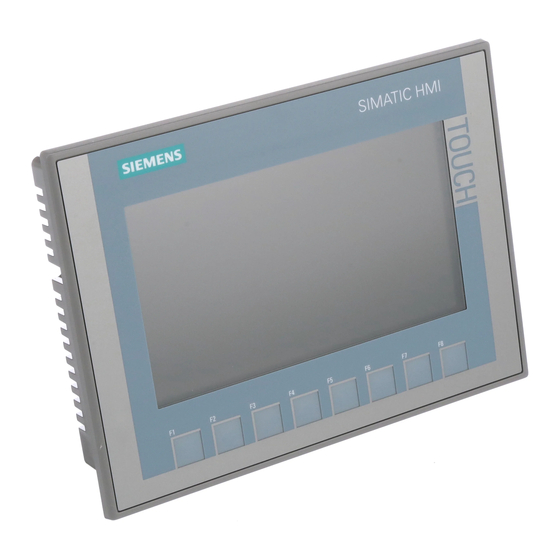
Overview 1.3 Design of the built-in units 1.3.2 IFP1500/1900/2200 Touch This section describes the design of the monitor and touch devices, using the IFP1500 Touch as an example. Front view and side view ① Display/touch screen ② Recesses for mounting clips ③... -
Page 16: Ifp1500 Touch/Key
Overview 1.3 Design of the built-in units 1.3.3 IFP1500 Touch/Key Front view ① Display and function keys with LED ② Alphanumeric keys ③ Control keys ④ Cursor keys ⑤ USB port 1.3.4 Interfaces 1.3.4.1 Standard versions ① X80 connector for 24 V DC power supply ②... -
Page 17: Ethernet Monitor Devices
Overview 1.3 Design of the built-in units 1.3.4.2 Ethernet Monitor devices ① X80 connector for 24 V DC power supply ② X1 Ethernet port ③ Reset button ④ X70 DisplayPort interface ⑤ X61/X62 USB Type A ⑥ X60 USB Type B 1.3.4.3 Extended versions ①... -
Page 18: Design Of The Pro Devices
Overview 1.4 Design of the PRO devices Design of the PRO devices 1.4.1 PRO devices for support arm (not extendable, flange top) The following figures show the design of the devices using the IFP1900 PRO for support arm (not extendable, flange top) as an example. Front view and side view ①... -
Page 19: Pro Devices For Pedestal (Extendable, Flange Bottom)
Overview 1.4 Design of the PRO devices Rear view ① Mechanical interface for fastening ② Rating plate ③ Enclosure ④ Backplane cover 1.4.2 PRO devices for pedestal (extendable, flange bottom) The following figures show the design of the devices using the IFP1900 PRO for pedestal (extendable, flange bottom) as an example. - Page 20 Overview 1.4 Design of the PRO devices Bottom view ① Mechanical interface for fastening Rear view ① Backplane cover ② Enclosure ③ Rating plate ④ Mechanical interface for fastening IFP, IFP PRO, IFP ETH Operating Instructions, 11/2017, A5E31298376-AH...
-
Page 21: Pro Devices For Support Arm (Extendable, Round Tube)
Overview 1.4 Design of the PRO devices 1.4.3 PRO devices for support arm (extendable, round tube) The following figures show the design of the devices using IFP1900 PRO for support arm (extendable, round tube) as an example. Front view and side view ①... -
Page 22: Interfaces
Overview 1.4 Design of the PRO devices Rear view ① Mechanical interface for fastening (round tube) ② Terminal compartment cover ③ Nameplate ④ Mechanical interface below ⑤ Lower cover, included in the product package 1.4.4 Interfaces ① ⑤ Protective conductor terminal X61/X62 USB Type A ②... -
Page 23: System Components And Accessories
Overview 1.5 System components and accessories System components and accessories System components are products that have been developed for a specific system and can not be used in general, for example, like the base adapter. System components are always directly related to a core product. Accessories can typically be used for multiple devices from the same or different device families, for example, batteries, touch pens or protective membranes. - Page 24 ● A Siemens VESA adapter set for VESA compatible systems ● Manufacturer-specific adapters or couplings The following table shows the available Siemens adapter sets and examples of vendor- specific adapter versions: Adapter version Suitable for supporting arm systems...
- Page 25 Overview 1.5 System components and accessories Flange mount adapter A flange mount adapter is available for mounting a PRO device for support arm (extendable, round tube). ① Flange mount adapter ② Ring groove for fastening on PRO device with setscrews ③...
- Page 26 In addition, different operator controls, such as Emergency Stop pushbutton, selector switch, illuminated pushbutton, keyswitch, indicator light and RFID reader, are available. Note Only operator controls with Siemens approval may be installed in the Extension Unit. Additional information You can find additional information on system components for full-enclosed IP65-protected devices on the Internet (https://mall.industry.siemens.com/mall/en/WW/Catalog/Products/10268745).
-
Page 27: Accessories
This section contains the number of accessories available at the time of publication of the operating instructions. You will find additional accessories on the Internet at: All Industrial Flat Panels ● Industry Mall (https://mall.industry.siemens.com) ● Expansion components and accessories (http://www.automation.siemens.com/mcms/pc- based-automation/en/industrial-pc/expansion_components_accessories) ●... - Page 28 Overview 1.5 System components and accessories Touch/Key Extended version Name Article number Film for labeling the function Print templates for the slide-in labels are 6AV7672-0DA00-0AA0 keys (slide-in labels) available on the "Documentation and Drivers" CD/DVD. Ethernet Monitors Name Specification Article number Recommended Ethernet RJ45 TP Cord RJ45/RJ45, 15 m 6XV1870-3QN15...
-
Page 29: Safety Information
Safety information General safety instructions The device is designed for use in the industrial sector for operating and monitoring plant processes. Machinery Directive WARNING The device may only be used in machines which comply with the Machinery Directive The Machinery Directive specifies precautions to be taken when commissioning and operating machinery within the European Economic Area. - Page 30 Siemens’ products and solutions undergo continuous development to make them more secure. Siemens strongly recommends that product updates are applied as soon as they are available and that the latest product versions are used. Use of product versions that are no longer supported, and failure to apply latest updates may increase customer’s exposure to...
-
Page 31: Notes About Usage
2.2 Notes about usage Disclaimer for third-party software updates This product includes third-party software. Siemens AG only provides a warranty for updates/patches of the third-party software, if these have been distributed as part of a Siemens software update service contract or officially released by Siemens AG. Otherwise, updates/patches are undertaken at your own risk. - Page 32 Safety information 2.2 Notes about usage Note 24 V DC devices The device is intended for operation in an SELV circuit according to IEC/EN 61010-2-201 in a dry environment, which means for the various device types: • Built-in units: dry environment on the rear of the device •...
- Page 33 Safety information 2.2 Notes about usage Use with additional measures The device should not be used at the following locations unless additional measures are taken: ● In locations with a high degree of ionizing radiation ● In locations with severe operating conditions, for example, due to: –...
- Page 34 (e.g. a clean air supply). • Only use suitable detergents. Read the information about Chemical resistance of the HMI devices and industrial PCs (http://support.automation.siemens.com/WW/view/en/39718396) on the Internet. TFT displays NOTICE Burn-in effect, backlighting A permanent picture with bright screen objects can have a burn-in effect.
-
Page 35: Use In Hazardous Areas
Safety information 2.3 Use in hazardous areas Defective pixels in the display The manufacturing process of modern displays does not currently guarantee that all pixels of the display are perfect. It is therefore inevitable that the display will contain a small number of defective pixels. - Page 36 Safety information 2.3 Use in hazardous areas IFP, IFP PRO, IFP ETH Operating Instructions, 11/2017, A5E31298376-AH...
-
Page 37: Installing And Connecting The Device
Installing and connecting the device Preparing for installation 3.1.1 Checking the delivery package Procedure 1. When accepting a delivery, please check the packaging for visible transport damage. 2. If any transport damage is present at the time of delivery, lodge a complaint at the shipping company in charge. -
Page 38: Built-In Unit
Installing and connecting the device 3.1 Preparing for installation NOTICE Damage from condensation If the device is subjected to low temperatures or extreme fluctuations in temperature during transportation, as is the case in cold weather, for example, moisture can build up on or inside the device (condensation). - Page 39 Installing and connecting the device 3.1 Preparing for installation Mounting position Select one of the approved mounting positions for your device. The approved mounting positions are described in the following sections. Mounting in horizontal format All devices are suitable for horizontal mounting positions. A maximum ambient temperature of +50 °C is permitted for vertical mounting of the IFP1500 (0°...
-
Page 40: Checking Clearances
Installing and connecting the device 3.1 Preparing for installation 3.1.2.2 Checking clearances The following clearances are required around the device to ensure adequate self-ventilation: ● At least 15 mm to the right and left of the mounting cutout (in x direction) to allow for insertion of the mounting clips during installation ●... -
Page 41: Preparing The Mounting Cutout
Installing and connecting the device 3.1 Preparing for installation 3.1.2.3 Preparing the mounting cutout Note Stability of the mounting cutout The material in the area of the mounting cutout must be sturdy enough to ensure permanent safe mounting of the device. To achieve the degrees of protection described below, it must be ensured that deformation of the material cannot occur due to the force of the mounting clips or operation of the device. -
Page 42: Labeling The Function Keys
Labeling strip templates are available in a Word document on the Internet at: Labeling strips for 15" widescreen (http://support.automation.siemens.com/DE/view/en/59000814) If you would like to make your own labeling strips, you can find the dimensions under "Dimensions for labeling strips (Page 106)". - Page 43 Installing and connecting the device 3.1 Preparing for installation The figure below shows the positions of the guides for the labeling strips of the 15" Touch/Key version. ① Guide for labeling strips F1, F3 ... F15 ② Guide for labeling strips F2, F4 ... F16 ③...
-
Page 44: Pro Devices
Installing and connecting the device 3.2 Installing the built-in unit 3.1.3 PRO devices 3.1.3.1 Permitted mounting positions The device is intended for mounting on a support arm or stand. The figure below shows the permitted mounting positions and the associated ambient temperatures using a device for stand mounting as an example. -
Page 45: Mounting Clips Or Mounting Brackets, Position For Ip65
Installing and connecting the device 3.2 Installing the built-in unit ● Ensure that the protective contact socket of the building installation is easily accessible and that there is a mains disconnect switch in switchgear cabinet installations. ● Position the device so that it is not exposed to direct sunlight. ●... - Page 46 Installing and connecting the device 3.2 Installing the built-in unit Positions of the mounting clips or mounting brackets for IP65 To achieve the IP65 degree of protection for the device, the mounting clips or brackets must be affixed at the positions shown below. Device Position Touch screen device with:...
-
Page 47: Fastening The Device With Mounting Clips Or Mounting Brackets
Installing and connecting the device 3.2 Installing the built-in unit 3.2.3 Fastening the device with mounting clips or mounting brackets Requirement ● All packaging components and protective films have been removed from the device. ● The mounting clips included in the accessory kit are to hand. Procedure Note If the mounting seal is damaged, the degree of protection is not guaranteed. -
Page 48: Position Of The Mounting Clips For Ip66-Complaint Installation
Installing and connecting the device 3.2 Installing the built-in unit Mounting with optional mounting brackets Mounting brackets can be used instead of mounting clips in steps 1 to 5: 3.2.4 Position of the mounting clips for IP66-complaint installation Positions of the mounting clips To achieve IP66 degree of protection instead of IP65 for a device with capacitive multi-touch screen, fasten 4 additional mounting clips (available as accessories) at the positions marked by the red boxes. -
Page 49: Mounting The Pro Device
Installing and connecting the device 3.3 Mounting the PRO device Mounting the PRO device 3.3.1 Notes on mounting WARNING The device must be mounted securely. Inadequately dimensioned fasteners may cause the device to fall down. Serious physical injury may result. Make sure that fasteners are adequately dimensioned during installation. - Page 50 Liability disclaimer The device is mounted to a pedestal or a support arm via the mechanical interface with screws. Siemens AG assumes no liability for the consequences of incorrect installation. Warranty at risk If you do not install the HMI device in accordance with the specifications in these operating instructions, the warranty for the device is voided.
-
Page 51: Pro Devices For Support Arm (Not Extendable, Flange Top) And For Pedestal (Extendable, Flange Bottom)
Requirement ● All packaging components and protective films have been removed. ● Siemens basic adapter with screws, included in product package of a PRO device for support arm (not extendable, flange top) or for pedestal (extendable, flange bottom). ● One of the following support arms or pedestal systems: –... - Page 52 A device for a support arm system cannot be used on a pedestal, and vice versa. 1. If an adapter plate for the Siemens base adapter is included in your support arm system, attach the adapter plate to the support arm with 4 M6x12 screws. Pay attention to the torque that is specified for the support arm.
-
Page 53: Pro Devices For Support Arm (Extendable, Round Tube)
The following figures show an example of how to attach the PRO device to a support arm system using the optionally available Siemens flange mount. The same approach is used to mount the PRO device to a 48.3 mm round tube. - Page 54 3. Attach the flange mount or the 48.3 mm round tube with the two M8 threaded pins. Observe the appropriate torque: – Siemens flange mount: 8 Nm – 48.3 mm steel round tube 8 Nm – 48.3 mm aluminum round tube: 5 Nm...
- Page 55 Installing and connecting the device 3.3 Mounting the PRO device 4. When you are using an adapter plate from a Siemens VESA adapter set, attach the adapter plate to the support arm with 4 M6x12 screws. When you are using another adapter plate matching the Siemens flange mount, attach the adapter plate to the support arm with the supplied mounting hardware.
-
Page 56: Connecting The Device
Installing and connecting the device 3.4 Connecting the device Connecting the device 3.4.1 Notes on connection Requirement ● The device has been installed according to the information provided in these operating instructions. Connecting cables Note Use copper cables at connectors with terminal connections Use copper (Cu) cables for all supply lines that are connected to the device with terminals, e.g. -
Page 57: Earthing The Device
Installing and connecting the device 3.4 Connecting the device Connecting the cables NOTICE Observe local installation regulations Observe the local installation guidelines and the local installation conditions, such as protective wiring for power supply cables, when connecting the cables. Short-circuit and overload protection Different measures for short-circuit and overload protection are required when setting up an entire plant. -
Page 58: Connecting The Power Supply
Installing and connecting the device 3.4 Connecting the device Procedure The figure below shows the connection of a protective conductor in a built-in unit. Proceed the same way as you would when connecting an equipotential-bonding cable in a built-in unit or the PRO device. -
Page 59: Connecting Devices With 24 V Dc 2-Pin
An external protective circuit is required for operation with 24 V DC, see section 7 "Lightning protection and overvoltage protection" in function manual "Designing interference-free controllers (https://support.industry.siemens.com/cs/ww/en/view/59193566)". The following lightning protection element was used during the testing of the Industrial Flat Panel: Dehn BVT AVD 24" (Order No. 918 422) - Page 60 Installing and connecting the device 3.4 Connecting the device Procedure 1. Ensure that the cable ends of the power supply lines are fitted with end sleeves. 2. Switch off the 24 V DC power supply. 3. Fasten the end of a connecting cable L+ and a connecting cable M with the supplied power supply connector.
-
Page 61: Connecting Devices With 3-Pin 24 V Dc
An external protective circuit is required for operation with 24 V DC, see section 7 "Lightning protection and overvoltage protection" in function manual "Designing interference-free controllers (https://support.industry.siemens.com/cs/ww/en/view/59193566)". The following lightning protection element was used during the testing of the Industrial Flat Panel: Dehn BVT AVD 24" (Order No. 918 422) -
Page 62: Connecting An Ac Power Supply
Installing and connecting the device 3.4 Connecting the device Procedure 1. Switch off the external 24 V DC power supply. 2. Connect the 24 V DC power supply connector to the device. Observe the correct polarity of the contacts: ① DC 24 V ②... - Page 63 Installing and connecting the device 3.4 Connecting the device Regional information Outside the United States and Canada, in regions with 230 V supply voltage: If you do not use the safety-certified power cable, use a flexible, double-insulated power supply cable (no single cables) with the following characteristics: ●...
-
Page 64: Connecting Ifp Standard, Extended And Pro To A Pc
Installing and connecting the device 3.4 Connecting the device Procedure • Plug the connector of the supplied power supply cable into the AC power supply connector of the device. 3.4.4 Connecting IFP Standard, Extended and PRO to a PC 3.4.4.1 Overview Connection diagram for standard monitor version Connection diagram for standard touch version... - Page 65 Connection diagram for Extended versions and PRO devices (24 V DC only) Distance up to 5 meters Distance of 5m to 30m See also Internet entry for possible number of IFPs on different IPCs (https://support.industry.siemens.com/cs/ww/en/view/109483774) IFP, IFP PRO, IFP ETH Operating Instructions, 11/2017, A5E31298376-AH...
-
Page 66: Standard Version
Installing and connecting the device 3.4 Connecting the device 3.4.4.2 Standard version Procedure 1. Connect the Flat Panel and the PC using a DVI or DisplayPort line. 2. If using a Touch version, also connect the device and the PC with a USB line. -
Page 67: Connecting Ethernet Monitor To A Pc
Connecting Ethernet Monitor to a PC 3.4.5.1 Overview Connection diagram for "Commissioning" mode Connection diagram for "Ethernet" mode See also Internet entry for possible number of IFPs on different IPCs (https://support.industry.siemens.com/cs/ww/en/view/109483774) IFP, IFP PRO, IFP ETH Operating Instructions, 11/2017, A5E31298376-AH... -
Page 68: Connection Versions
Installing and connecting the device 3.4 Connecting the device 3.4.5.2 Connection versions "Commissioning" mode When you commission an Ethernet Monitor with the "Ethernet Monitor" software or want to change the network parameters of an Ethernet Monitor, connect the Ethernet Monitor and IPC in the "Commissioning"... -
Page 69: Securing The Cables
Installing and connecting the device 3.4 Connecting the device Note Functional problem with USB port If you connect an external device with a 230 V power supply to the USB port without using a non-insulated installation, you may experience functional problems. Use a non-insulated system design. -
Page 70: Securing Cables For Use In Hazardous Areas
Installing and connecting the device 3.4 Connecting the device The figure below shows the fasteners of the IFP1900 PRO. 3.4.8 Securing cables for use in hazardous areas For securing the connected cables, use the appropriate mounting elements, as described in the previous chapter. -
Page 71: Commissioning The Device
Commissioning the device If you operate the device exclusively as monitor and do not change the brightness, you do not need to commission the device. To use advanced functions of the device, perform the following commissioning. Requirement ● The Industrial Flat Panel is mounted according to the Quick Install Guide. ●... - Page 72 Commissioning the device IFP, IFP PRO, IFP ETH Operating Instructions, 11/2017, A5E31298376-AH...
-
Page 73: Operating The Device
Operating the device Operator input options Depending on your device and the connected I/O devices, the following operator input options are available: ● Integrated keyboard on touch device (not for all IPC) ● Touch screen for touch device CAUTION Unintentional actions with touch screen operation If you touch the touch screen while system-internal processes are running, unintended reactions of the device may be triggered. -
Page 74: Operating A Device With Resistive Single Touch Screen
Operating the device 5.2 Operating a device with resistive single touch screen Operating a device with resistive single touch screen When you touch an object on the single touch screen, the corresponding function is performed. WARNING Personal injury or property damage due to incorrect operation Incorrect operation of devices with a touch screen can occur. -
Page 75: Operating A Device With Capacitive Multi-Touch Screen
Operating the device 5.3 Operating a device with capacitive multi-touch screen Operating a device with capacitive multi-touch screen You operate the multi-touch screen with one or multiple fingers. You can also operate it using gestures with up to five fingers at a time. WARNING Personal injury or property damage due to no earth connection An inadequate earth connection or the lack of one may cause malfunction of the capacitive... - Page 76 Operating the device 5.3 Operating a device with capacitive multi-touch screen WARNING Danger of malfunction due to improper execution of gestures on the touch screen If gestures are executed incorrectly on the touch screen with multi-touch function, these gestures may not be recognized or could be recognized incorrectly. The entries made are then not implemented by the device or are implemented incorrectly or in an unintended manner.
-
Page 77: Operating A Touch/Key Device
Operating the device 5.4 Operating a Touch/Key device Functions of the multi-touch screen General functions ● Detection of up to 5 finger touches at a time. ● Detection of gestures that are supported by the operating system or the software installed on the device. - Page 78 Operating the device 5.4 Operating a Touch/Key device External keyboard Note The keyboard layout has been set to "English/USA international". If you use a keyboard with a layout other than the "English/USA international" layout, the key codes of the internal and external keyboards might no longer correspond.
- Page 79 Operating the device 5.4 Operating a Touch/Key device Control keys The following table describes the control keys and their associated functions. With keyboard shortcuts, hold the first key down. Then press the second button. Key or keyboard Function shortcut Switch between upper and lower case: LED on: Upper case •...
-
Page 80: Advanced Device Functions
Operating the device 5.5 Advanced device functions Cursor keys Key or keyboard Function shortcut Moves the cursor, selection or a controller in the specified direction. Moves the cursor or selection one page up. Moves the cursor or selection one page down. Moves the cursor to the start of the first screen. -
Page 81: Maintaining And Servicing Your Device
Maintaining and servicing your device General information on maintenance and servicing Observe the following when servicing and repairing protective features such as ground circuits, overvoltage protection components or batteries: ● Observe the maintenance and replacement intervals specified by the respective manufacturer for all system components. -
Page 82: Ethernet Monitors - Diagnostics And Reset
Maintaining and servicing your device 6.3 Ethernet Monitors - Diagnostics and reset Ethernet Monitors - Diagnostics and reset 6.3.1 Diagnostics screen The diagnostics screen shows information on the system state of the Ethernet Monitor when no picture is displayed. The diagnostics screen is not displayed permanently; it alternates with a black screen. -
Page 83: Restoring The Factory Settings For An Ethernet Monitor
Maintaining and servicing your device 6.3 Ethernet Monitors - Diagnostics and reset 6.3.2 Restoring the factory settings for an Ethernet Monitor When the Ethernet Monitor was operated in the LAN network, it has an individual IP address. When you connect the Ethernet Monitor to another location in the network, it is no longer found because the Ethernet Monitor software is looking for the default IP address. -
Page 84: Spare Parts And Repairs
Kraftwerkstraße 25a 91056 Erlangen Germany See also Spare parts and repairs (http://support.automation.siemens.com/WW/view/en/16611927) Recycling and disposal The devices described in these operating instructions can be recycled thanks to their low level of pollutants. Contact a certified disposal service company for environmentally sound recycling and disposal of your old devices. -
Page 85: Technical Information
P.O. Box 1963 D-92209 Amberg, Germany You can download information on the EC Declaration of Conformity, here under the keyword "Declaration of Conformity": ● IFP certificates (https://support.industry.siemens.com/cs/ww/en/ps/16788/cert) ● IFP PRO certificates (https://support.industry.siemens.com/cs/ww/en/ps/21662/cert) IFP, IFP PRO, IFP ETH Operating Instructions, 11/2017, A5E31298376-AH... - Page 86 Technical information 7.1 Certificates and approvals Software license agreements If the device is supplied with preinstalled software, you must observe the corresponding license agreements. UL approval See the following notes: ● The device shall be supplied from an isolating source, rated 24 VDC. ●...
- Page 87 II 3 D Ex tc IIIC T 70 °C Dc Observe all information on the Internet (https://support.industry.siemens.com/cs/ww/en/view/291285) regarding use of the device in hazardous areas. When using the device in hazardous areas, ensure that all connectors connected to the device are secured in a captive manner, see section "Securing cables for use in hazardous areas (Page 70)".
- Page 88 Technical information 7.1 Certificates and approvals FCC and Canada Federal This equipment has been tested and found to comply with the limits for a Class Communications A digital device, pursuant to Part 15 of the FCC Rules. These limits are Commission designed to provide reasonable protection against harmful interference when the equipment is operated in a commercial environment.
-
Page 89: Directives And Declarations
Technical information 7.2 Directives and declarations WEEE label (European Union) Disposal instructions, observe the local regulations and the section "Recycling and disposal (Page 84)". Marine approvals Acceptance procedures for shipping and offshore applications: ● ABS American Bureau of Shipping (USA) ●... - Page 90 Technical information 7.2 Directives and declarations NOTICE Damage to ESD from touch Electrostatic sensitive devices, ESD, can be destroyed by voltages which are far below the human perception limit. If you touch a component or electrical connections of a module without discharging any electrostatic energy, these voltages may arise.
- Page 91 Technical information 7.2 Directives and declarations NOTICE Grounding measures There is no equipotential bonding without grounding. An electrostatic charge is not discharged and may damage the ESD. Protect yourself against discharge of static electricity. When working with electrostatic sensitive devices, make sure that the person and the workplace are properly grounded. Protective measures against discharge of static electricity ●...
-
Page 92: Dimension Drawings
Technical information 7.3 Dimension drawings Dimension drawings 7.3.1 Dimension drawing of the IFP1500 Multitouch IFP, IFP PRO, IFP ETH Operating Instructions, 11/2017, A5E31298376-AH... -
Page 93: Dimension Drawing Of The Ifp1500 Monitor And Touch
Technical information 7.3 Dimension drawings 7.3.2 Dimension drawing of the IFP1500 Monitor and Touch IFP, IFP PRO, IFP ETH Operating Instructions, 11/2017, A5E31298376-AH... -
Page 94: Dimension Drawing Of The Ifp1900 Multitouch And Ifp1900 Eth
Technical information 7.3 Dimension drawings 7.3.3 Dimension drawing of the IFP1900 Multitouch and IFP1900 ETH IFP, IFP PRO, IFP ETH Operating Instructions, 11/2017, A5E31298376-AH... -
Page 95: Dimension Drawing Of The Ifp1900 Monitor And Touch
Technical information 7.3 Dimension drawings 7.3.4 Dimension drawing of the IFP1900 Monitor and Touch IFP, IFP PRO, IFP ETH Operating Instructions, 11/2017, A5E31298376-AH... -
Page 96: Dimension Drawing Of The Ifp2200 Multitouch And Ifp2200 Eth
Technical information 7.3 Dimension drawings 7.3.5 Dimension drawing of the IFP2200 Multitouch and IFP2200 ETH IFP, IFP PRO, IFP ETH Operating Instructions, 11/2017, A5E31298376-AH... -
Page 97: Dimension Drawing Of The Ifp2200 Monitor And Touch
Technical information 7.3 Dimension drawings 7.3.6 Dimension drawing of the IFP2200 Monitor and Touch IFP, IFP PRO, IFP ETH Operating Instructions, 11/2017, A5E31298376-AH... -
Page 98: Dimension Dimensional Drawing Of The Ifp1900 Pro
Technical information 7.3 Dimension drawings 7.3.7 Dimension dimensional drawing of the IFP1900 PRO IFP1900 PRO for pedestal (extendable, flange bottom) ① Without base adapter ② With base adapter IFP, IFP PRO, IFP ETH Operating Instructions, 11/2017, A5E31298376-AH... - Page 99 Technical information 7.3 Dimension drawings IFP1900 PRO for support arm (not extendable, flange top) ① Without base adapter ② With base adapter IFP, IFP PRO, IFP ETH Operating Instructions, 11/2017, A5E31298376-AH...
- Page 100 Technical information 7.3 Dimension drawings IFP1900 PRO for support arm (extendable, round tube) ① Without flange mount ② With flange mount IFP, IFP PRO, IFP ETH Operating Instructions, 11/2017, A5E31298376-AH...
-
Page 101: Dimension Drawing Of The Ifp2200 Pro
Technical information 7.3 Dimension drawings 7.3.8 Dimension drawing of the IFP2200 PRO IFP2200 PRO for pedestal (extendable, flange bottom) ① Without base adapter ② With base adapter IFP, IFP PRO, IFP ETH Operating Instructions, 11/2017, A5E31298376-AH... - Page 102 Technical information 7.3 Dimension drawings IFP2200 PRO for support arm (not extendable, flange top) ① Without base adapter ② With base adapter IFP, IFP PRO, IFP ETH Operating Instructions, 11/2017, A5E31298376-AH...
- Page 103 Technical information 7.3 Dimension drawings IFP2200 PRO for support arm (extendable, round tube) ① Without flange mount ② With flange mount IFP, IFP PRO, IFP ETH Operating Instructions, 11/2017, A5E31298376-AH...
-
Page 104: Dimension Drawing Of The Ifp1500 Touch/Key
Technical information 7.3 Dimension drawings 7.3.9 Dimension drawing of the IFP1500 Touch/Key IFP, IFP PRO, IFP ETH Operating Instructions, 11/2017, A5E31298376-AH... -
Page 105: Dimension Drawing Host Unit Usb
Technical information 7.3 Dimension drawings 7.3.10 Dimension drawing Host Unit USB The Host Unit USB is available as an accessory (DVI/USB cable sets >5 m). IFP, IFP PRO, IFP ETH Operating Instructions, 11/2017, A5E31298376-AH... -
Page 106: Dimensions For Labeling Strips
This section contains the dimensions of the labeling strips for 15" widescreen devices. Labeling strip templates are available in a Word document on the Internet at: Labeling strips for 15" widescreen (http://support.automation.siemens.com/DE/view/en/59000814) IFP, IFP PRO, IFP ETH Operating Instructions, 11/2017, A5E31298376-AH... -
Page 107: Rating Plate
Technical information 7.4 Rating plate Rating plate The rating plate includes information that clearly identifies your device. You need this information when you contact Customer Support. The figure below shows an example of a rating plate. ① Order number ② Serial number ③... - Page 108 Technical information 7.5 Technical specifications Display IFP1500 IFP1500 IFP1900 IFP2200 Type LCD widescreen TFT Active display area 15.4'' 15.6'' 18.5'' 21.5'' 344.2 × 193.5 mm 331.2 × 207 mm 409.8 × 230.4 mm 475.2 × 267.3 mm Resolution 1280 x 800 pixels 1366 x 768 pixels 1366 x 768 pixels 1920 x 1080 pixels...
- Page 109 Technical information 7.5 Technical specifications Interfaces Monitor standard Touch standard Touch Extended/ ETH versions IFP1500 versions versions PRO devices Touch/Key DVI-D DisplayPort USB Type A, rear USB Type A, front USB Type B, host USB-Link/Ethernet, RJ45 USB type A, maximum load 500 mA, equivalent to USB standard 2.0 DC power supply IFP1500 IFP1900...
-
Page 110: Ambient Conditions
Technical information 7.5 Technical specifications 7.5.2 Ambient conditions 7.5.2.1 Transport and storage conditions Proper transport and storage, installation and assembly as well as careful operation and maintenance are prerequisites for trouble-free and safe operation of the device. Non-compliance with these regulations shall render the device warranty void. Mechanical transport and storage conditions The following information is for a device that is transported and stored in its original packaging. -
Page 111: Operating Conditions
Technical information 7.5 Technical specifications 7.5.2.2 Operating conditions Mechanical and climatic conditions of use The device is designed for use in locations protected from the effects of the weather. The conditions of use meet the requirements for DIN IEC 60721-3-3: ●... - Page 112 Technical information 7.5 Technical specifications Climatic ambient conditions The following table shows the climatic ambient conditions for operation of the device. Ambient conditions Permitted range Comments Temperature built-in units: 0 ... 50 °C (landscape format) Vertical mounting • 0 ... 40 °C (portrait format) 0 ...
-
Page 113: Electromagnetic Compatibility
Powerful single pulse (surge) according to IEC 61000-4-5, external protective circuit is required (see function manual "SIMATIC S7-1500, ET 200MP, ET 200SP, ET 200AL Designing interference-free controllers", section 7 "Lightning protection and overvoltage protection") on the Internet (https://support.industry.siemens.com/cs/ww/en/view/59193566). Asymmetrical 2 kV power supply cable... -
Page 114: Information On Insulation Tests, Protection Class And Degree Of Protection
Technical information 7.5 Technical specifications Emission of radio interference The following table shows the emitted interference from electromagnetic fields according to EN 61000-6-4, measured at a distance of 10 m. Radiated emission (emitted interference) 1 GHz to 3 GHz < 66 dB peak and < 46 dB average 3 GHz to 6 GHz <... -
Page 115: Interface Description
Technical information 7.6 Interface description Protection against foreign objects and water PRO device Degree of protection Explanation All-round When mounted: IP65 according to IEC 60529 • Enclosure Type 4X / 12 (indoor use only) according to UL50 • The degree of protection can only be guaranteed if the seals are completely flush at the mechanical interfaces and the associated covers are closed. -
Page 116: Dvi-D Interface
Technical information 7.6 Interface description 7.6.2 DVI-D interface DVI-D interface Pin no. Abbreviation Signal TX2N TDMS data 2- TX2P TDMS data 2+ TMDS data shield 2, ground Not assigned Not assigned DDC CLK DDC clock DDC CLK DDC data Not assigned TX1N TDMS data 1- TX1P... -
Page 117: Displayport
Technical information 7.6 Interface description 7.6.3 DisplayPort DisplayPort interface Pin no. Abbreviation Meaning Input/output ML_Lane3- DP data 3- Input Ground ML_Lane3+ DP data 3+ Input ML_Lane2- DP data 2- Input Ground ML_Lane2+ DP data 2+ Input ML_Lane1- DP data 1- Input Ground ML_Lane1+... -
Page 118: Usb Hub, Type A
Technical information 7.6 Interface description 7.6.5 USB hub, Type A USB port Pin No. Abbreviation Signal + 5 V (fused) - Data Data channel + Data Data channel Ground 7.6.6 Ethernet Ethernet RJ45 interface Pin no. Short description Meaning Input / output BI_DA+ Bi-directional data A+ Input/output... -
Page 119: Technical Support
Always use the current documentation available for your product. You can find the latest edition of this manual and other important documents by entering the article number of your device on the Internet (https://support.industry.siemens.com). If necessary, filter the comments for the entry type "Manual". -
Page 120: Troubleshooting
Technical Support A.2 Troubleshooting Troubleshooting Ethernet Monitors Error pattern Possible cause Possible remedy The Windows Start screen is Occurs when Uninstalling cannot be performed with an not visible and only the uninstalling the Ethernet Monitor. Use a different monitor extended desktop is displayed. Ethernet Monitor for uninstalling. -
Page 121: Markings And Symbols
Markings and symbols Safety-relevant symbols The following table describes symbols that can be added to your SIMATIC device, to its packaging or to an enclosed document in addition to the symbols described in the manuals. Symbol Meaning Reference General danger sign Caution / Attention ISO 7000 No. - Page 122 Markings and symbols B.1 Safety-relevant symbols Symbol Meaning Reference Only for industrial applications and indoor areas (control cabinet) Install in control cabinet only Devices approved for Ex Zone 2 in a control cabinet with min. IP54 Devices approved for Ex Zone 22 in a control cabinet with min. IP6x IFP, IFP PRO, IFP ETH Operating Instructions, 11/2017, A5E31298376-AH...
-
Page 123: List Of Abbreviations
List of abbreviations ANSI American National Standards Institute ASCII American Standard Code for Information Interchange Width Backlight Inverter BIOS Basic Input Output System CD-ROM Compact Disc – Read Only Memory Central Processing Unit Direct Current DHCP Dynamic Host Configuration Protocol Domain Name Service Distributed I/O Data Source Name... - Page 124 List of abbreviations IFP, IFP PRO, IFP ETH Operating Instructions, 11/2017, A5E31298376-AH...
-
Page 125: Glossary
Glossary Application An application is a program which is put directly on the operating system MS-DOS or windows. An application on the PC/PG, for example, is STEP 7. Controller Installed hardware and software which control the functions of specific internal or external devices, e.g. - Page 126 Glossary Module Modules are plug-in units for PLCs, programming devices or PCs. Modules exist, for example, as central modules, power-ons, or as mass storage. Plug and play Through plug and play, the computer configures itself automatically to be able to communicate with peripheral devices, e.g.
-
Page 127: Index
Index Connecting, 66 2-pole DC power supply, 59 3-pole DC power supply, 61 AC power supply, 62 Abbreviations, 123 Cables, 57 AC power supply DVI, 66 Technical specifications, 109 Protective conductor, 58 ACK key, 79 USB, 66 Acknowledge key, 79 USB device, 68 Alphanumeric keys, 78 Connecting the PE conductor, 58... - Page 128 Index ESD Directive, 89 Ethernet interface, 118 Ethernet Monitor ACK, 79 Views, 13 ALT, 79 Extension Unit, 26 Backspace, 79 Cancel, 79 CTRL, 79 Cursor, 80 Factory settings Delete, 79 Ethernet Monitor, 83 END, 80 FCC, 88 ENTER, 79 Flange mount adapter, 25 ESC, 79 FM Approval, 86 HOME, 80...
- Page 129 Index Mounting position Protection class, 114 Built-in unit, 39 Protective conductor, 57 Protective measure PRO device, 44 Multi-touch device Static electricity, 91 Views, 13 Radiation, 29 New Zealand, 88 High-frequency radiation, 29 Note Radio interference, 32 General information, 34 Emission, 114 Rated load Interface, 69 Regional information, 63...
- Page 130 Index TAB key, 79 Technical specifications, 107 Test For ambient conditions, 111 Touch screen Operation, 73 Touch screen device Views, 15 Touch/key device Views, 16 Transport and storage conditions, 110 Troubleshooting Ethernet Monitor, 120 Turning off, 58 UL approval, 86 USA, 63 USB device Connecting, 68...
Need help?
Do you have a question about the SIMATIC HMI series and is the answer not in the manual?
Questions and answers