
Related Manuals for Rion UN-14


Summary of Contents for Rion UN-14
- Page 1 INSTRUCTION MANUAL SOUND LEVEL METER UNIT UN-14 3-20-41 Higashimotomachi, Kokubunji, Tokyo 185-8533, Japan http://www.rion.co.jp/english/...
- Page 3 This manual describes the features, operation, and other aspects of the Sound Level Meter Unit UN-14. If the unit is used together with other equipment to confi gure a measurement system, consult the documentation of all other components as well.
- Page 4 Performance Characteristics Contains charts that show the frequency weighting characteristics, characteristics of the high-pass filter and low-pass filter as well as the influence of extension cables. Specifi cations Lists the technical specifi cations of the unit. Reference Material Provides an explanation of group delay, microphone measurement range, user fi lters, and maintenance parts.
-
Page 5: For Safety
FOR SAFETY In this manual, important safety instructions are specially marked as shown below. To prevent the risk of severe damage to the unit or peripheral equipment, make sure that all instructions are fully understood and observed. Caution D isrega rd i ng i nst r uct ions printed here incurs the risk of injury to persons and/or damage to peripheral equipment. - Page 6 The product described in this manual is in conformity with the following standards; Electrical equipment for measurement control and laboratory use. RION Co., Ltd. 3-20-41 Higashimotomachi, Kokubunji, Tokyo 185-8533, Japan...
-
Page 7: Precautions
Precautions • Operate the unit only as described in this manual. • Do not disassemble the unit or attempt internal alterations. • Observe the following precautions before using the unit: Make sure that all connections are properly and safely established. Make sure that the unit is operating normally. -
Page 8: Table Of Contents
Linking procedure ..............12 Removing the cable from the link connector ......17 Linking with Battery Unit BP-17 ..........18 Using a single UN-14 unit ............19 Linking with Interface Unit UV-22 .........20 Power Supply Connection ............. 21 Using an AC adapter ...............22 Using the Battery Unit BP-17 ..........23... - Page 9 Operation Modes ................31 Input setup mode ..............31 Sensitivity setting ..............32 1) Direct input of sensitivity setting ........32 2) Calibration with Sound Calibrator NC-75/NC-74 or Pistonphone NC-72A ........... 36 3) TEDS communication mode ......... 41 Setting the ID number ............42 Measurement setup mode ............44 Calibration mode (OUTPUT CAL) .........46 Measurement mode ..............47...
- Page 10 viii...
-
Page 11: Outline
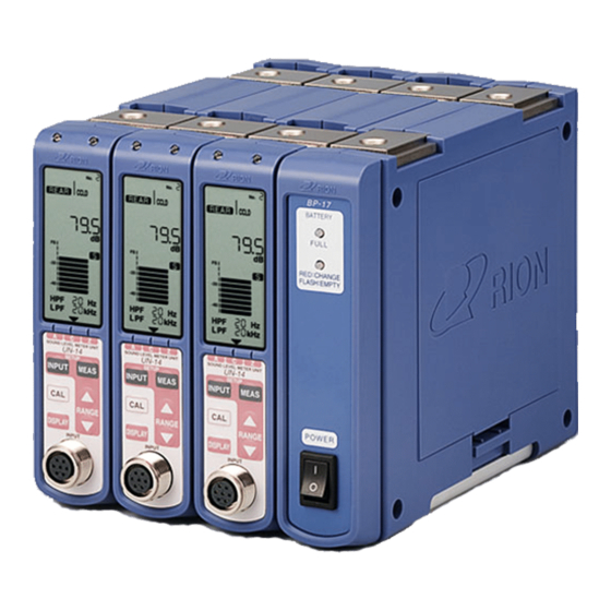
Outline The UN-14 is a single-channel sound level meter unit designed for connection of a measurement microphone and preamplifi er. The chassis of up to 16 units can be linked to create a multi-channel confi guration. Two types of input connectors are provided (7-pin and BNC), providing support for the following types of microphones and preamplifi ers. - Page 12 Battery Unit BP-17 Designed to hold eight IEC R14 (size C) batteries, this unit can be linked to the UN-14 and/or UV-15 to provide power. The power switch on the front panel of the BP-17 can be used to switch the entire system on and off.
- Page 13 Outline UN-14 Block Diagram 7-pin connector (Front panel) OVER AMP 3 Preamplifier power supply±12 V AMP 4 Microphone bias power supply 30 V/60 V/200 V DC ATT 1 AMP 1 BNC connector ATT 2 (Rear panel) AMP 2 CCLD 24 V 4 mA...
-
Page 14: Names Of Parts And Functions
Names of Parts and Functions Front panel Sub LED Overload indicator LED LCD panel SOUND LEVEL METER UNIT UN-14 SETUP MEAS INPUT Operation panel RANGE DISPLAY INPUT Microphone input connector Sub LED Lights up in green when the Master/Slave function is used. -
Page 15: Operation Panel
Names of Parts and Functions Operation panel Control keys for measurement mode (level range selection, display switching etc.) are located here. (For details, see pages 9 to 10.) LCD panel Shows setup information, a bar graph display, numeric readout etc. When the unit is powered from batteries using the Battery Unit BP-17, the display backlight is activated for 10 seconds when any key is pressed. -
Page 16: Rear Panel
INPUT (CCLD/ TEDS) INPUT connector AC OUT AC OUT connector DC OUT DC OUT connector RION CO.,LTD. MADE IN JAPAN No. 12345678 Name plate DC IN 9-15V DC IN jack INPUT connector This connector is designed for connection of a CCLD type preamplifi er or microphone. -
Page 17: Lcd Panel
Names of Parts and Functions LCD panel ID number indication FRONT indicator REAR CCLD/TEDS indicators ACOUST/CAL indicators RANGE/SENS indicators Numeric readout Unit indicator Time weighting indicators F/S/10 ms Bar graph HPF indicator LPF indicator Arrow indicators REAR CCLD/TEDS indicators Show whether REAR CCLD or REAR CCLD TEDS have been selected for the input. - Page 18 A, C, and Z. The arrow for the currently selected characteristic is visible. Frequency weighting characteristic indicated by arrow ( Select with RANGE keys SOUND LEVEL METER UNIT Frequency weighting characteristics UN-14 SETUP LPF indicator Shows the selected low-pass fi lter setting. HPF indicator Shows the selected high-pass fi lter setting.
-
Page 19: Operation Panel
Names of Parts and Functions Operation panel A/C/Z indicators SOUND LEVEL METER UNIT UN-14 SETUP MEAS key INPUT key INPUT MEAS CAL key RANGE keys RANGE DISPLAY key DISPLAY INPUT MEAS key This key serves to select settings for the following input related items. - Page 20 ID number setting A/C/Z indicators Show the frequency weighting characteristics selected with the RANGE keys. Arrow ( ) for selected frequency weighting characteristics flashes ("C" in illustration) Select with RANGE keys SOUND LEVEL METER UNIT Frequency weighting characteristics UN-14 SETUP INPUT MEAS...
-
Page 21: Top Panel
Names of Parts and Functions Top panel The top panel of the unit has two hooks which can be used to join multiple units together. Top view Link hook Link hook Bottom panel Removing the cover plates on the bottom of the unit gives access to a connector that is used to supply power when linking multiple units. -
Page 22: Linking
Linking Multiple UN-14 units can be linked to form a multi-channel system. The maximum number of units that can be linked is 16. Linking with UV-15 units (option) is also possible. When using the Battery Unit BP-17 to provide power, the maximum number of units that can be linked is three. - Page 23 Linking 2. Remove the two link hooks on the top panel. Do not remove these hooks for the unit that will be the rightmost unit as seen from the front. Put the screws and hooks in a box or other suitable container, to make sure that you do not lose any parts.
- Page 24 Linking 4. Plug the link connector of each unit into the next unit. Front side Rolled up link connector and cable Unit bottom Plug into link connector 5. After plugging in the link connectors, use the supplied link plates and screws to provisionally join the units as shown below. Use the screws removed in step 1.
- Page 25 Linking 6. Attach the link hooks removed in step 2 to the unit tops, so that the units are locked together. Lock unit tops with link hooks Link hooks Attach link hook on rightmost unit with orientation as shown Rotate 90 degrees Front side Insert link hook into slit on next unit and fasten 7.
- Page 26 Linking 8. Attach the link hooks to the unit tops, so that the units are locked together. Securely tighten all screws. Unit top Front side Note If you have lost the original screws, refer to the information about maintenance parts on page 66. Commercially available screws can also be used, provided that exact specifi cations are met.
-
Page 27: Removing The Cable From The Link Connector
Linking Removing the cable from the link connector To unplug the link connector, grasp the tag as shown in the illustration below and carefully pull the connector out. Important Be sure to grasp the side with the "3M" lettering. If you pull on the other side, the tag may break. Side with "3M"... -
Page 28: Linking With Battery Unit Bp-17
The cover of the battery compartment in the Battery Unit BP-17 is located on the right side. When installed in this way, the cover can be opened to access the compartment and insert/remove batteries. Sound Level Meter Unit UN-14 (up to three units when powered by batteries) BP-17 BATTERY... -
Page 29: Using A Single Un-14 Unit
Linking Using a single UN-14 unit Attach the supplied link plate to the bottom of the unit as shown below, to stabilize the unit when it is used in a free-standing confi guration. Use the screws removed from the unit. -
Page 30: Linking With Interface Unit Uv-22
Linking Linking with Interface Unit UV-22 Install the Interface Unit UV-22 as the leftmost unit as seen from the front. Sound Level Meter Unit UN-14 UV-22 LOCAL MASTER/SLAVE ETHERNET POWER RESET RED:ERROR SOUND LEVEL METER UNIT SOUND LEVEL METER UNIT... -
Page 31: Power Supply Connection
The UN-14 can be powered from an AC adapter (option), the Battery Unit BP-17 (option), or a car battery (12 V). The UN-14 does not have a power switch. It will start to operate when power is supplied. The Battery Unit BP-17 (option) and Interface Unit UV-22 (option) have a power switch which allows shutting down the system. -
Page 32: Using An Ac Adapter
Do not use any AC adapter other than the specifi ed models. Otherwise malfunction and damage may occur. If no Battery Unit BP-17 or Interface Unit UV-22 is installed in the system, the AC adapter may be connected to any UN-14 unit. INPUT (CCLD/ TEDS) -
Page 33: Using The Battery Unit Bp-17
Using the Battery Unit BP-17 Battery life Figures for approximate battery life when using the Battery Unit BP-17 are given below. These fi gures are for using three UN-14 units. Manganese batteries Approx. 1.5 hours Alkaline batteries Approx. 6 hours Continuous operation at ambient temperature of 25ºC, with FRONT setting, normal... - Page 34 When not using the unit, remove the batteries to guard against the risk of damage by leaking battery fl uid. When powering a system from batteries using the BP-17, the maximum number of UN-14 units that can be linked is three.
- Page 35 The Battery Unit BP-17 does not have a charging function. If a system which includes the UN-14 and the Battery Unit BP-17 is to be powered by an AC adapter, be sure to connect the AC adapter to the BP-17.
-
Page 36: Microphone Connection
UN-14. The UN-14 has is equipped with an input connector on the front panel and one on the rear panel. For details on the combination of microphone, preamplifi er, and extension cable, see page 28. - Page 37 (CCLD/ TEDS) Microphone UC-52, UC-53A AC OUT UC-57, UC-59 DC OUT Preamplifier NH-22A RION CO.,LTD. MADE IN JAPAN No. 12345678 DC IN 9-15V BNC-BNC coaxial cable EC-90A: 2 m EC-90B: 5 m Note When connecting a TEDS compliant sensor, the allowable cable length for TEDS communication should be 20 meters or less on the condition as follows.
-
Page 38: Possible Microphone/Preamplifi Er/Extension Cable Combinations
EC-04D: 40 m (BNC) 1/4-inch microphone adapter EC-04E: 100 m Rear panel NC-75-S11 Sound Level Meter Unit Sound Calibrator NC-75 Extension cable UN-14 EC-04: 1/2-inch microphone adapter Microphone input EC-04A: 5 m NC-75-022 connector (7-pin) Front panel EC-04B: 10 m... - Page 39 Microphone Connection To use a microphone tripod, fasten the microphone holder supplied with the extension cable to the tripod, and plug the connector of the extension cable into the microphone holder. Preampli er Connector Preampli er NH-04A NH-05A NH-06A NH-17A Microphone holder EC03001 Extension cable...
-
Page 40: Output Connections
Output Connections The rear panel of the UN-14 provides one AC output connector and one DC output connector. These can be used to supply a signal for example to an oscilloscope for waveform observation, to a data recorder for recording, or to an FFT analyzer for analysis. -
Page 41: Operation Modes
Input setup mode This serves to make settings for the connected microphone and preamplifi er and select an ID number for the UN-14. Be sure to make or check these set- tings before starting a measurement. Input setup mode functions... -
Page 42: Sensitivity Setting
Use the RANGE keys to change and select the setting. Press the INPUT key when the setting has been made. ID number indication (Flashes during setup) SOUND LEVEL METER UNIT Input connector setting UN-14 SETUP (Flashes during setup) MEAS key INPUT key INPUT... - Page 43 1 V/Pa) 22.1 mV/Pa Cartridge Capacitance : 17.8 Leakage Resistance : > at Relative Humidity<85% Conditions of Tests : 1000 Frequency: Polarization Voltage: Barometric Pressure: mmHg Relative Humidity: Temperature: RION CO., LTD Ч0.1 Ч1 Ч10 RP-00 Calibration chart (example)
- Page 44 Operation Modes The preamplifier loss (loss caused by microphone capacitance and preampli- fier capacitance) can be determined from the chart below, according to the equipment combination. 1-inch 1/2-inch 1/4-inch Microphone UC-27 UC-30 UC-52 UC-53A UC-57 UC-59 UC-54 UC-29 UC-32P UC-31 Preampli er UC-33P NH-04, NH-12...
- Page 45 Operation Modes Example Combination of 1/2-inch condenser microphone UC-52 (sensitivity −32.9 dB) and preamplifi er NH-17A (loss −0.4 dB) (−32.9) + (−0.4) = −33.3 Consequently, the sensitivity value to enter is "−33.3". Use RANGE keys to set value to microphone sensitivity + preamplifier loss 4.
-
Page 46: Calibration With Sound Calibrator Nc-75/Nc-74 Or Pistonphone Nc-72A
Operation Modes 2) Calibration with Sound Calibrator NC-75/NC-74 or Pistonphone NC-72A This section describes the procedure for mounting the Sound Calibrator NC-75/NC-74 or Pistonphone NC-72A on the microphone and performing acoustic calibration by matching the indicated level to the sound pressure level inside the coupler. - Page 47 7. When the sound pressure level of the Sound Calibrator NC-75/NC-74 or Pistonphone NC-72A is the same as the measurement value at the UN-14, the setting is completed. Press the INPUT key to return to the OUTPUT CAL mode, and press the CAL key to return to the measurement mode.
- Page 48 Operation Modes To perform calibration using a 1/2-inch condenser microphone, mount the 1/2-inch adapter on the coupler of the Sound Calibrator NC-75/NC-74 or Pistonphone NC-72A. The adapter is not required when using a 1-inch condenser microphone. 1/2 inch adapter Pistonphone NC-72A 1/4 inch adapter for NC-74 1/2 inch adapter...
- Page 49 Operation Modes The calibration values for the Sound Calibrator NC-75/NC-74 are listed in the table below. Calibration value (dB) Nominal diameter Microphone model NC-75 NC-74 UC-11 93.8 93.8 UC-25 93.6 93.5 1-inch UC-27 93.8 93.8 UC-34 93.9 93.8 UC-26 93.9 93.9 UC-30 94.0...
- Page 50 Operation Modes Note For details on using the Sound Calibrator NC-75/ NC-74 or Pistonphone NC-72A, refer to the docu- mentation of the respective product. Information about atmospheric pressure compensation is provided in the documentation of the Pistonphone NC-72A. The Sound Calibrator NC-75/NC-74 is designed and manufactured to produce a sound pressure level of 94.0 dB under the rated conditions.
-
Page 51: Teds Communication Mode
Operation Modes 3) TEDS communication mode In this mode, the UN-14 communicates with the TEDS sensor to receive sensitivity information and set the sensitivity accordingly. TEDS communication can be carried out in the input setup mode. If a TEDS sensor was used previously, TEDS communication will also be carried out when power is supplied the next time. -
Page 52: Setting The Id Number
Operation Modes Setting the ID number When the UN-14 is used in conjunction with the Interface Unit UV-22, an ID number for the UN-14 must be set fi rst. To set the ID number, the keys on the operational panel of the respective UN-14 unit must be used. - Page 53 Operation Modes 1. When you press the INPUT key on the operation panel of the UN-14 three times in succession, the ID number starts to fl ash. 2. Use the RANGE keys to set the number. When the setting is complete, press the MEAS key to enable the setting and return to the measurement screen.
-
Page 54: Measurement Setup Mode
[ ] Select with RANGE keys Frequency weighting SOUND LEVEL METER UNIT characteristics UN-14 SETUP Setup procedure 1) Pressing the MEAS key in measurement mode allows you to set the time weighting characteristics. You can change the setting with the RANGE keys. - Page 55 OFF: ---, 20 kHz: "20 kHz" shown Selected frequency weighting is indicated by flashing arrow SOUND LEVEL METER UNIT Frequency weighting characteristics A, C, Z UN-14 SETUP MEAS INPUT In measurement setup mode, all items that can be changed are shown, and...
-
Page 56: Calibration Mode (Output Cal)
Operation Modes Calibration mode (OUTPUT CAL) This mode serves for electrical calibration of external equipment connected to the BNC connectors on the rear panel. Calibration procedure 1. Press the CAL key while the unit is in measurement mode. 2. While the CAL key is being held down, the AC OUT and DC OUT connectors on the rear panel supply a calibration signal for use as reference (range full-scale value −6 dB). -
Page 57: Measurement Mode
HPF indication OFF/20 Hz When OFF, Frequency weighting "---" is shown indication LPF indication OFF/20 kHz Points to A/C/Z SOUND LEVEL METER UNIT When OFF, UN-14 SETUP Frequency weighting "---" is shown MEAS INPUT characteristics A/C/Z Normal measurement mode (Instantaneous value indication) Changing the range The RANGE keys can be used to change the range setting. -
Page 58: Overload Indicator Led
In this case, correct measurement is not possible. Use the RANGE keys to change the level range setting so that the LED does not light up. Overload indicator LED SOUND LEVEL METER UNIT UN-14 SETUP MEAS INPUT RANGE... -
Page 59: Relationship Between Ac Out Signal Voltage And Sound Pressure Level
Operation Modes Relationship between AC OUT signal voltage and sound pressure level The AC signal supplied at the AC OUT connector on the rear panel corre- sponds to the selected frequency weighting and HPF and LPF settings. The amplitude of the signal can be calculated from the selected range and the voltage value. -
Page 60: Dc Out Signal
Operation Modes DC OUT signal The DC signal supplied at the DC OUT connector on the rear panel is ob- tained by rms conversion of the AC signal using the selected time weighting characteristics. − − − − − − FS: Range full-scale value Example for level range 120 setting Range... -
Page 61: Check Mode
Operation Modes Check mode You can check the software version of the UN-14 as follows. 1. Pressing the CAL key while the unit is in measurement mode activates OUTPUT CAL mode. 2. Hold down the RANGE key for at least 2 seconds, until the version number is shown on the numeric readout of the LCD panel. -
Page 62: Using The Interface Unit Uv-22 (Option)
Both USB and Ethernet connections are supported. Sound Level Meter Unit UN-14 (max. 16 units) Interface Unit UV-22 To Ethernet or USB port... - Page 63 Operation Modes • User fi lter settings One cutoff frequency as specifi ed below can be added to the HPF and LPF settings. For information on user fi lter frequencies, see pages 64 and 65 in the "Reference Material" section starting on page 62. HPF cutoff frequency (attenuation −18 dB/oct): Any center frequency from 3 Hz to 160 Hz can be specifi ed, in 1/3 octave steps.
-
Page 64: Factory Default Settings
Operation Modes Factory default settings The factory default settings are as follows. Input settings INPUT: FRONT Sensitivity: −29.9 dB ID number: Level range: Numeric readout: Measurement value Frequency weighting: Time weighting: HPF: OFF (display shows ---) LPF: OFF (display shows ---) Restoring the factory default settings Turning power to the unit on while holding down the MEAS key will clear the resume information and return the unit to the factory default... -
Page 65: Performance Characteristics
Performance Characteristics Frequency response characteristics The frequency weighting curves of the UN-14 (representative characteristics) are shown below. Z (Flat) Z (Flat) − − − − − − − − 50 100 500 1 k 5 k 10 k 50 k 80 k... -
Page 66: Infl Uence Of Extension Cable Ec-04 Series
Performance Characteristics Infl uence of extension cable EC-04 series Due to the capacitance between the signal lines and shield of the extension cable EC-04 series, there are limitations with regard to the maximum sound pressure and frequency that can be measured. This phenomenon is plotted in the diagram below. -
Page 67: Specifi Cations
Inputs Number of measurement channels Connectors 7-pin input connector (on front panel) For Rion measurement microphone or preamplifi er Max. input voltage ±10 V Microphone bias voltage +30 V, +60 V, +200 V BNC connector (on rear panel) For CCLD compliant microphone or preamplifi er TEDS compliance rating IEEE 1451.4-2000 Template ID 12.27.28... - Page 68 Specifi cations Sensitivity setting Setting range −10.0 dB/Pa to −59.9 dB/Pa in 0.1-dB/Pa steps Level range settings 6 settings Sensitivity value Level range −10.0 to −19.9 70 dB to 120 dB in 10-dB steps −20.0 to −29.9 80 dB to 130 dB in 10-dB steps −30.0 to −39.9 90 dB to 140 dB in 10-dB steps −40.0 to −49.9...
- Page 69 Rear (using NH-22A, UC-59): approx. 170 mA (12 V) Suitable AC adapter NC-99 series:(max. 16 UN-14 units and one UV-22) Max. 85 VA with 16 UN-14 units (100 V AC) NC-97 series:(max. 10 UN-14 units and one UV-22) Battery Unit...
- Page 70 Instruction manual Inspection certifi cate Optional accessories Interface Unit UV-22 Vibration Meter Unit UV-15 AC adapter NC-99 series (max. 16 UN-14 units and one UV-22) NC-97 series (max. 10 UN-14 units and one UV-22) Battery Unit BP-17 Measurement microphone Various...
-
Page 71: Dimensional Drawing
Specifi cations INPUT (CCLD/ TEDS) AC OUT DC OUT SOUND LEVEL METER UNIT UN-14 RION CO.,LTD. SETUP MADE IN JAPAN INPUT MEAS No. 12345678 RANGE DC IN DISPLAY 9-15V INPUT Side view Front view Rear view Unit: mm Dimensional Drawing... -
Page 72: Reference Material
Reference Material Delay of output signal The UN-14 incorporates an A/D converter which converts the microphone input signal into digital format for processing by a DSP chip. The result is then returned to analog format by a D/A converter and output as an AC and DC signal. -
Page 73: Measurement Range
Reference Material Measurement Range The frequency and level range that can be measured depends on the combi- nation of microphone and preamplifi er. Frequency range (representative characteristics) The measurement frequency range specifi cations of various microphones are indicated below. Microphone UC-27 UC-32P UC-30... -
Page 74: User Filter
When used in conjunction with the UV-22, one each of the HPF and LPF characteristics shown below can be added as a user fi lter. Available user fi lter frequency characteristics are as follows. UN-14 user fi lter characteristics for HPF UN-14 user filter characteristics for HPF 3 Hz 3.15 Hz... - Page 75 Reference Material UN-14 user fi lter characteristics for LPF UN-14 user filter characteristics for LPF 50 kHz 300 Hz 40 kHz 315 Hz 31.5 kHz 400 Hz 25 kHz 500 Hz 20 kHz 630 Hz 16 kHz 800 Hz 15 kHz 1 kHz 12.5 kHz...
-
Page 76: Maintenance Parts
Part name: Cover plate Part number: UV-16-008 M3 pan-head screw Part name: M3 pan-head screw Cover plates Rion designation: KS 3 × 10 Conventional market designation: Unit bottom Pan-head screw M3 × 10 Screw length 10 mm Part name: Link hook... - Page 78 This product is environment-friendly. It does not include toxic chemicals on our policy. No. 52136 18-03...
Need help?
Do you have a question about the UN-14 and is the answer not in the manual?
Questions and answers