
Related Manuals for Rion UV-15


Summary of Contents for Rion UV-15
- Page 1 INSTRUCTION MANUAL Vibration Meter Unit UV-15 3-20-41 Higashimotomachi, Kokubunji, Tokyo 185-8533, Japan http://www.rion.co.jp/english/...
- Page 3 Organization of this manual This manual describes the features, operation, and other aspects of the Vibration Meter Unit UV-15. If the unit is used together with other equipment to confi gure a measurement system, consult the documentation of all other components as well.
- Page 4 Performance Characteristics Contains charts that show the characteristics of the high-pass fi lter and low- pass fi lter as well as velocity (VEL) and displacement (DISP) frequency response characteristics. Specifi cations Lists the technical specifi cations of the unit. Reference Material Provides an explanation of output signal delay.
-
Page 5: For Safety
FOR SAFETY In this manual, important safety instructions are specially marked as shown below. To prevent the risk of death or injury to persons and severe damage to the unit or peripheral equipment, make sure that all instructions are fully understood and observed. - Page 6 The product described in this manual is in conformity with the following standards; Electrical equipment for measurement control and laboratory use. Core Core AC adapter NC-99 series Core A: ZCAT2749-0430 (TDK) Core B~H: ZCAT2436-1330 (TDK) Equivalent product RION Co., Ltd. 3-20-41 Higashimotomachi, Kokubunji, Tokyo 185-8533, Japan...
-
Page 7: Precautions
Precautions • Operate the unit only as described in this manual. • Do not disassemble the unit or attempt internal alterations. • Observe the following precautions before using the unit: Make sure that all connections are properly and safely established. Make sure that the unit is operating normally. -
Page 8: Table Of Contents
Removing the cable from the link connector ......17 Linking with Battery Unit BP-17 ..........18 Linking with Interface Unit UV-22 ..........19 Using a single UV-15 unit ............20 Power Supply Connection .............. 21 Using an AC adapter ..............22 Using the Battery Unit BP-17 ...........23 Accelerometer Selection and Connection ........25... - Page 9 Operation Modes ................31 Input setup mode ..............31 TEDS communication mode ............34 Setting the ID number .............35 Measurement setup mode ............36 Calibration mode (OUTPUT CAL) ..........38 Measurement mode ..............39 Measurement range ............41 Frequency range ..............41 Measurement upper limit ............ 41 Measurement lower limit ............42 Check mode ................45 Using the Interface Unit UV-22 (option) ........46...
- Page 10 viii...
-
Page 11: Outline
Outline The UV-15 is a single-channel vibration meter unit with a wide measurement range. It supports connection of piezoelectric accelerometers, accelerom- eters with integrated preamplifi er (24 V DC, 4 mA power supplied), TEDS compliant accelerometers with integrated preamplifi er, and accelerometers connected via the Preamplifi er VP-26A. - Page 12 Outline Interface Unit UV-22 Linking the UV-22 allows connection to a computer for controlling the sound and vibration level measurement system and for transfer of measurement data. Both USB and Ethernet connections are supported.
- Page 13 Outline UV-15 Block Diagram Microdot ACC (m/s Charge amplifier 0 dB connector Integrator VEL (mm/s) Charge amplifier -20 dB DISP (mm) Integrator OVER CCLD 24 V 4 mA OVER AMP 1 TEDS AMP 2 AMP 0 dB AMP 3 AMP 4...
-
Page 14: Names Of Parts And Functions
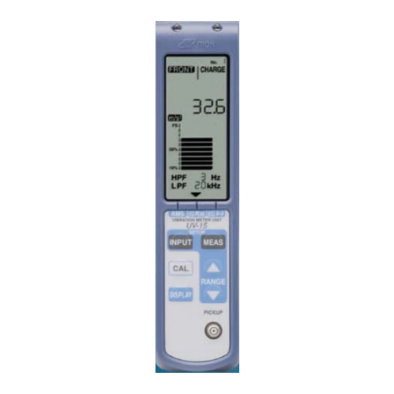
Names of Parts and Functions Front panel Sub LED Overload indicator LED LCD panel EQ PEAK EQ P-P VIBRATION METER UNIT UV-15 SETUP MEAS INPUT Operation panel RANGE DISPLAY PICKUP PICKUP connector Sub LED Lights up in green when a control command from the Interface Unit UV-22 has been received normally and when the Master/Slave function is used. - Page 15 Names of Parts and Functions Operation panel Control keys for measurement mode (range selection, display switching etc.) are located here. LCD panel Shows setup information, a bar graph display, numeric display etc. When the unit is powered from batteries using the Battery Unit BP-17, the display backlight is activated for 10 seconds when any key is pressed.
-
Page 16: Rear Panel
INPUT (PREAMP) INPUT (PREAMP) connector AC OUT AC OUT connector DC OUT DC OUT connector RION CO.,LTD. MADE IN JAPAN No. 12345678 Name plate DC IN 9-15V DC IN jack INPUT (PREAMP) connector This connector is designed for connection of a piezoelectric accelerometer via the Preamplifi er VP-26A. -
Page 17: Lcd Panel
Names of Parts and Functions LCD panel REMOTE ID number indication FRONT CHARGE Input indicators REAR CCLD TEDS ACOUST Calibration indicator RANGE SENS Range/sensitivity indicators Numeric display mm/s mm Unit indicators 10ms Bar graph HPF indicator LPF indicator Arrow indicators LCD panel ID number indication Serves to identify the unit in a multi-channel confi guration. - Page 18 Names of Parts and Functions Unit indicators Show the measurement unit for the currently selected measurement mode. • Acceleration (ACC): • Velocity (VEL): mm/s • Displacement (DISP): mm During sensitivity indication, no unit is shown. Arrow indicators Below these arrows are labels for RMS, EQ PEAK, and EQ P-P indica- tion characteristics.
-
Page 19: Operation Panel
Names of Parts and Functions Operation panel EQ PEAK EQ P-P RMS, EQ PEAK, EQ P-P labels VIBRATION METER UNIT UV-15 SETUP MEAS INPUT INPUT key MEAS key CAL key RANGE RANGE keys DISPLAY DISPLAY key PICKUP PICKUP connector (See page 4) MEAS key Serves to select the following modes. - Page 20 Names of Parts and Functions DISPLAY key Serves to switch the numeric display between range indication and mea- surement value indication. CAL key Pressing this key causes the AC OUT and DC OUT connectors on the rear panel to supply a calibration signal for calibration of external equip- ment.
-
Page 21: Top Panel
Names of Parts and Functions Top panel The top panel of the unit has two hooks which can be used to join multiple units together. Top view Link hook Link hook Bottom panel Removing the cover plates on the bottom of the unit gives access to a con- nector that is used to supply power when linking multiple units. -
Page 22: Linking
Linking Multiple UV-15 units can be linked to form a multi-channel system. The maximum number of units that can be linked is 16. The Sound level Meter Unit UN-14, Battery Unit BP-17, and Interface Unit UV-22 can also be used. - Page 23 Linking 2. Remove the two link hooks on the top panel. Do not remove these hooks for the unit that will be the rightmost unit as seen from the front. Put the screws and hooks in a box or other suitable container, to make sure that you do not lose any parts.
- Page 24 Linking 4. Plug the link connector of each unit into the link connector of the next unit. Front side Rolled up link connector and cable Unit bottom Plug into link connector 5. After plugging in the link connectors, use the link plates and screws to provisionally join the units as shown below.
- Page 25 Linking 6. Attach the link hooks removed in step 2 to the unit tops, so that the units are locked together. Lock unit tops with link hooks Link hooks Attach link hook on rightmost unit with orientation as shown Rotate 90 degrees Front side Insert link hook into slit on next unit and fasten 7.
- Page 26 Linking 8. Attach the link hooks to the unit tops, so that the units are locked together. Securely tighten all screws. Unit top Front side Note If you have lost the original screws, refer to the information about maintenance parts on page 60. Commercially available screws can also be used, provided that exact specifi cations are met.
-
Page 27: Removing The Cable From The Link Connector
Linking Removing the cable from the link connector To unplug the link connector, grasp the tag as shown in the illustration below and carefully pull the connector out. Important Be sure to grasp the side with the "3M" letter- ing. If you pull on the other side, the tag may break. -
Page 28: Linking With Battery Unit Bp-17
The cover of the battery compartment in the Battery Unit BP-17 is located on the right side. When installed in this way, the cover can be opened to access the compartment and insert/remove batteries. Vibration Meter Unit UV-15 (up to three units when powered by batteries) BP-17... -
Page 29: Linking With Interface Unit Uv-22
Linking Linking with Interface Unit UV-22 Install the Interface Unit UV-22 as the leftmost unit as seen from the front. Vibration Meter Unit UV-15 UV-22 LOCAL MASTER/SLAVE ETHERNET POWER RESET RED:ERROR EQ PEAK EQ P-P EQ PEAK EQ P-P EQ PEAK... -
Page 30: Using A Single Uv-15 Unit
Linking Using a single UV-15 unit Attach the supplied link plate to the bottom of the unit as shown below, to stabilize the unit when it is used in a free-standing confi guration. Use the screws removed from the unit. -
Page 31: Power Supply Connection
The UV-15 can be powered from an AC adapter (option), the Battery Unit BP-17 (option), or a car battery (12 V). The UV-15 does not have a power switch. It will start to operate when power is supplied. The Battery Unit BP-17 (option) and Interface Unit UV-22 have a power switch which allows shutting down the system. -
Page 32: Using An Ac Adapter
Do not use any AC adapter other than the specifi ed models. Otherwise malfunction and damage may occur. If no Battery Unit BP-17 or Interface Unit UV-22 is installed in the system, the AC adapter may be connected to any UV-15 unit. INPUT (PREAMP) AC OUT... -
Page 33: Using The Battery Unit Bp-17
When not using the unit, remove the batteries to guard against the risk of damage by leaking battery fl uid. When powering a system from batteries using the BP-17, the maxi- mum number of UV-15 units that can be linked is three. - Page 34 The Battery Unit BP-17 does not have a charging function. If a system which includes the UV-15 and the Battery Unit BP-17 is to be powered by an AC adapter, be sure to connect the AC adapter to the BP-17.
-
Page 35: Accelerometer Selection And Connection
Accelerometer Selection and Connection The following types of accelerometers can be connected to the UV-15. Accelerometer type Sensitivity setting range Piezoelectric accelerometer 0.100 to 99.9 pC/(m/s Accelerometer with integrated preamplifi er 0.100 to 99.9 mV/(m/s TEDS compliant accelerometer with integrated preamplifi er 0.100 to 99.9 mV/(m/s... -
Page 36: Accelerometer Connection
Accelerometer Selection and Connection Accelerometer connection Connect the accelerometer to the PICKUP connector on the front panel of the UV-15, as shown in the illustration below. Vibration Meter Unit UV-15 Accelerometer Connection cable VP-51 series If the accelerometer cable uses BNC connectors, make the connection as follows. -
Page 37: Input (Preamp) Connector Wiring Diagram
Accelerometer Selection and Connection Connect the accelerometer to the INPUT (PREAMP) connector on the rear panel of the UV-15, as shown in the illustration below. Extension cable EC-02S series (option) INPUT (PREAMP) AC OUT Preamplifier DC OUT VP-26A RION CO.,LTD. -
Page 38: Accelerometer Mounting
Accelerometer Selection and Connection Accelerometer mounting The UV-15 is a vibration meter designed for use with piezoelectric acceler- ometers or accelerometers with integrated preamplifi er. Other types of ac- celerometers such as electrokinetic accelerometers cannot be used with this product due to different structure. Choose a suitable accelerometer according to the measurement requirements including measurement range, frequency range, and environmental conditions. - Page 39 Accelerometer Selection and Connection Rod attachment mounting Pressing the accelerometer against the measure- Accelerometer ment object with a rod is the simplest method, but the measurement frequency range would be about several hundred Hz, because the contact resonance frequency will be very low. This method should only be used if none of the other three mounting attachment methods are feasible.
-
Page 40: Output Connections
Output Connections The rear panel of the UV-15 provides one AC output connector and one DC output connector. These can be used to supply a signal for example to an oscilloscope for waveform observation, to a data recorder for recording, or to an FFT analyzer for analysis. -
Page 41: Operation Modes
Check the software version of the UV-15 Input setup mode This serves to make settings for the connected accelerometer and select an ID number for the UV-15. Be sure to make or check these settings before starting a measurement. Input setup mode functions... - Page 42 If FRONT CCLD TEDS was selected, the unit switches to TEDS com- munication mode when you press the INPUT key. (See page 34.) ID number indication EQ PEAK EQ P-P FRONT CHARGE VIBRATION METER UNIT Input indicators UV-15 REAR CCLD TEDS ACOUST SETUP RANGE SENS INPUT MEAS...
- Page 43 The ID number setting is required for unit identifi cation when multiple UN-14 and UV-15 units are used. For details, see page 35. The setting range is 1 to 16. Use the RANGE keys to select the number. Holding down a RANGE key changes the numeric value more quickly.
-
Page 44: Teds Communication Mode
Operation Modes TEDS communication mode In this mode, the UV-15 communicates with the TEDS sensor to receive sensitivity information and set the sensitivity accordingly. TEDS communication can also be carried out in the input setup mode. If a TEDS sensor was used previously, TEDS communication will also be carried out when power is supplied the next time. -
Page 45: Setting The Id Number
CO S ID number setup screen 1. When you press the INPUT key on the operation panel of the UV-15 three times in succession, the ID number starts to fl ash. 2. Use the RANGE keys to set the number. When the setting is complete, press the MEAS key to return to the measurement screen. -
Page 46: Measurement Setup Mode
Operation Modes Measurement setup mode This mode serves for selecting the measurement mode (unit), display char- acteristics, HPF (high-pass fi lter), and LPF (low-pass fi lter) settings. Be sure to make or check these settings before starting a measurement. Measurement setup mode functions Settings Select measurement mode (unit) (Acceleration: ACC), mm/s (Velocity: VEL), mm... - Page 47 Select measurement mode with EQ PEAK EQ P-P INPUT key VIBRATION METER UNIT MEAS key FRONT CHARGE UV-15 REAR Select unit with RANGE keys CCLD TEDS SETUP ACOUST Selected m/s flashes MEAS INPUT...
-
Page 48: Calibration Mode (Output Cal)
1 V (P-P) ±2% DC OUT: 1 V ±2% 3. Press the CAL key again to return to the measurement mode. EQ PEAK EQ P-P REMOTE VIBRATION METER UNIT FRONT CHARGE UV-15 REAR CCLD TEDS SETUP ACOUST CAL indication MEAS INPUT RANGE flashes... -
Page 49: Measurement Mode
RANGE indication 10ms EQ PEAK EQ P-P VIBRATION METER UNIT UV-15 Bar graph indication The bar graph indicator has 10 segments. The refresh cycle of the bar graph is 100 milliseconds. Range full-scale value (Example: 10 m/s when range setting is 10 m/s... - Page 50 LED to light up. In such a case, correct measurement is not possible, and you should increase the range setting. Overload indicator LED EQ PEAK EQ P-P VIBRATION METER UNIT UV-15 SETUP MEAS INPUT Numeric display RANGE keys RANGE...
-
Page 51: Measurement Range
Operation Modes Measurement range The measurable frequency range and measurement upper and lower limits depend on the accelerometer in use and the measurement mode. If the overload indicator LED lights up, the measurement upper limit is be- ing exceeded. Frequency range The frequency range for measurement depends on the measurement mode, as listed below. -
Page 52: Measurement Lower Limit
Operation Modes Measurement lower limit The lower limit for measurement is determined by the noise level. This is the level that is indicated when a dummy load of 1000 pF is connected to the PICKUP connector and the sensitivity switch is set to 5.00 pC/(m/s In order to limit the infl uence of noise upon the measurement to no more than 1 dB (approx. - Page 53 Operation Modes AC OUT signal The AC signal supplied at the AC OUT connector on the rear panel cor- responds to the selected measurement mode (acceleration/velocity/dis- placement) and HPF and LPF settings. The amplitude of the signal can be calculated from the selected range and the voltage value.
- Page 54 When saturation of the internal circuits occurs, the red overload indicator LED lights up. In this case, correct measurement is not possible. Overload indicator LED EQ PEAK EQ P-P VIBRATION METER UNIT UV-15 SETUP INPUT MEAS Numeric display RANGE keys...
-
Page 55: Check Mode
Operation Modes Check mode You can check the software version of the UV-15 as follows. 1. Press the CAL key while the unit is in measurement mode. 2. Hold down the RANGE key for at least 2 seconds, until the ver- sion number is shown on the LCD panel. -
Page 56: Using The Interface Unit Uv-22 (Option)
Both USB and Ethernet connections are supported. A Software UV-22Viewer is also supplied to the UV-22. Vibration Meter Unit UV-15 (max. 16 units) Interface Unit UV-22 UV-22 LOCAL... - Page 57 Operation Modes • User fi lter settings One cutoff frequency as specifi ed below can be added to the HPF and LPF settings. For information on user fi lter frequencies, see pages 58 and 59 in the "Reference Material" section. HPF cutoff frequency (attenuation −18 dB/oct): Any center frequency from 3.15 Hz to 160 Hz can be specifi ed, in 1/3 octave steps.
-
Page 58: Restoring The Factory Default Settings
Operation Modes Restoring the factory default settings Turning power to the unit on while holding down the MEAS key will clear the resume information and return the unit to the factory default condition. Input settings INPUT: FRONT CHARGE Sensitivity: 5.00 ID number: Range: Numeric display:... -
Page 59: Performance Characteristics
10 Hz 100 Hz 15 Hz −30 150 Hz 20 Hz 200 Hz −40 Frequency (Hz) UV-15 HPF frequency response characteristics LPF (low-pass fi lter) characteristics 3 kHz −10 300 Hz 5 kHz 500 Hz 10 kHz −20 1 kHz 15 kHz 1.5 kHz... - Page 60 Performance Characteristics VEL (velocity) and DISP (displacement) characteristics Velocity (VEL) displacement −10 (DISP) −20 −30 −40 −50 1000 Frequency (Hz) Velocity (VEL) and displacement (DISP) frequency response characteristics...
-
Page 61: Specifi Cations
Specifi cations Applicable standards CE marking Inputs Number of measurement channels Connectors Microdot connector For piezoelectric accelerometer Max. input charge 100,000 pC For accelerometer with integrated preamplifi er CCLD 24 V 4 mA For TEDS compliant accelerometer with integrated preamplifi er CCLD 24 V 4 mA 7-pin preamplifi er connector For connection of piezoelectric accelerometer via... - Page 62 Specifi cations Sensitivity 1.00 to 9.99 ACC (acceleration): 1, 3, 10, 30, 100, 300, 1000 VEL (velocity): 1, 3, 10, 30, 100, 300, 1000 DISP (displacement): 0.1, 0.3, 1, 3, 10, 30, 100 Sensitivity 10.0 to 99.9 ACC (acceleration): 0.1, 0.3, 1, 3, 10, 30, 100 VEL (velocity): 0.1, 0.3, 1, 3, 10, 30, 100 DISP (displacement):...
- Page 63 Specifi cations Filters HPF (attenuation −18 dB/oct, −10% dB drop) 3 Hz, 5 Hz, 10 Hz, 15 Hz, 20 Hz, 30 Hz, 50 Hz, 100 Hz, 150 Hz, 200 Hz, OFF LPF (attenuation -18 dB/oct, -10% dB drop) 300 Hz, 500 Hz, 1 kHz, 1.5 kHz, 2 kHz, 3 kHz, 5 kHz, 10 kHz, 15 kHz, 20 kHz, OFF Display Segment-type LCD with backlight (constantly on)
- Page 64 Specifi cations Outputs BNC connector × 2 AC output Output impedance 50 Ω Output voltage accuracy (80 Hz full-scale) ACC (acceleration) 1 V ±2% VEL (velocity) 1 V ±3% DISP (displacement) 1 V ±5% Maximum output voltage approx. ±10 V (peak) DC output Output impedance 50 Ω...
- Page 65 Suitable AC adapter: NC-99 series (up to sixteen UV-15 units and one UV-22 unit) (CE mark) 80 VA or less when using sixteen UV-15 units (100 V AC) NC-97 series (up to ten UV-15 units and one UV-22 unit) Battery Unit...
- Page 66 Specifi cations Supplied accessories Instruction manual Link plate Inspection certifi cate Optional accessories Sound level Meter Unit UN-14 Interface Unit UV-22 AC adapter NC-99 series (up to 16 units) (CE mark) NC-97 series (up to 10 units) Battery Unit BP-17 Piezoelectric accelerometer Various Accelerometer cable...
- Page 67 Specifi cations INPUT (PREAMP) AC OUT DC OUT EQ PEAK EQ P-P VIBRATION METER UNIT UV-15 RION CO.,LTD. SETUP MADE IN JAPAN MEAS INPUT No. 12345678 RANGE DC IN DISPLAY 9-15V PICKUP Rear view Front view Side view Unit: mm...
-
Page 68: Reference Material
Reference Material Delay of output signal The UV-15 incorporates an A/D converter which converts the vibration input signal into digital format for processing by a DSP chip. The result is then returned to analog format by a D/A converter and output as an AC and DC signal. -
Page 69: User Filter
When used in conjunction with the UV-22, one each of the HPF and LPF characteristics shown below can be added as a user fi lter. Available user fi lter frequency characteristics are as follows. UV-15 user fi lter characteristics for HPF UV-15 user filter characteristics for HPF −10 −20... - Page 70 Reference Material UV-15 user fi lter characteristics for LPF UV-15 user filter characteristics for LPF 20 kHz −10 16 kHz 15 kHz −20 12.5 kHz 10 kHz −30 8 kHz 6.3 kHz −40 5 kHz −50 10 k 50 k...
-
Page 71: Maintenance Parts
Part name: Cover plate Part number: UV-16-008 M3 pan-head screw Part name: M3 pan-head screw Cover plates Rion designation: KS 3 × 10 Conventional market designation: Unit bottom pan-head screw M3 × 10 Screw length 10 mm Part name: Link hook... - Page 72 This product is environment-friendly. It does not include toxic chemicals on our policy. No. 52117 18-07...
Need help?
Do you have a question about the UV-15 and is the answer not in the manual?
Questions and answers