
Related Manuals for Rion NL-42A


Summary of Contents for Rion NL-42A
- Page 1 INSTRUCTION MANUAL Sound Level Meter NL-42A / NL-52A 3-20-41 Higashimotomachi, Kokubunji, Tokyo 185-8533, Japan https://www.rion.co.jp/english/...
- Page 3 Organization of the NL-42A/NL-52A documentation Documentation for the Sound Level Meter NL-42A/NL-52A comes in three parts, as listed below. Instruction Manual (this document) Describes operating procedures for the NL-42A/NL-52A, connection and use of peripheral equipment such as a level recorder and printer, and use of the SD memory card.
- Page 5 Organization of this manual This manual describes the features, operation and other aspects of the NL-42A/ NL-52A. If the unit is used together with other equipment to confi gure a mea- surement system, consult the documentation of all other components as well.
- Page 6 Input/Output Connectors Explains the input and output connectors of the unit. Default Settings Lists the factory default settings of the unit. Setup Files Explains how to start up the unit using settings saved in a setup fi le. Optional Accessories Explains how to use the optional microphone extension cable, printer, and level recorder with the unit.
-
Page 7: For Safety
FOR SAFETY In this manual, important safety instructions are specially marked as shown below. To prevent the risk of death or injury to persons and severe damage to the unit or peripheral equipment, make sure that all instructions are fully understood and observed. - Page 9 Quantifi er Notation (Sound level and sound pressure level are expressed uniformly as sound pressure level, distinguished by the use of frequency weighting.) The time weighting characteristics Measurement value F, S A-weighted sound pressure level Sound pressure C-weighted sound pressure level level Z-weighted sound pressure level Equivalent continuous A-weighted...
- Page 10 viii...
- Page 11 Quantifi er Notation of NL-42A/NL-52A According to International Stan- dards and JIS (Excerpts from ISO 1996, ISO 3891, IEC 61672-1, JIS Z 8202, JIS Z 8731) NL-42A/52A Frequency Description notation notation notation notation weighting — Sound level — A-weighted sound level —...
- Page 12 100 V AC cord for domestic use in Japan, which is compliant with Japanese laws and electrical safety standards. Do not use this power cord outside Japan or with any voltage other than 100 V AC. Otherwise, RION cannot guarantee the safety of the equipment. Use a power cable that is compliant with the laws and electrical safety standards of your location.
- Page 13 Up to two units can be stored in the storage case. When storing the unit in an empty space, protect the unit by wrapping it with cushioning material. Note that we are not responsible for any failure or damage to the unit which occurs while the unit is stored in an empty space.
- Page 14 The life of the backup battery for the internal clock of the unit is lim- ited. You should have the battery replaced about once every fi ve years. Regarding replacement of the battery, please contact your supplier. Please note that this product is warranted up to the product purchase price against defects in material.
-
Page 15: Table Of Contents
Contents FOR SAFETY .................v Outline ....................1 Controls and Functions ..............5 Front view ..................5 Bottom view ................8 Rear view ...................9 Preparations .................. 10 Power ..................10 Power on/off ................14 Windscreen (WS-10, WS-15, WS-16) ........16 Diffuse sound fi eld correction ..........17 SD memory card and program cards ........ - Page 16 Processed data display screen other than L value ....46 Time-Level screen ..............47 Indicator messages ..............48 Menu list screen ...............49 System (Language) ............. 51 Display ................54 I/O ..................57 Store ...................59 Measure ................62 LN Mode ................64 Save/Print ................65 Option ................66 Recall .................67 WR ..................70 MENU list items ..............
- Page 17 Formatting an SD memory card ..........104 Screen hard copy ..............105 Input/Output Connectors ............. 106 AC OUT connector ..............106 DC OUT connector ..............108 I/O connector ................. 110 Default Settings ................111 Setup Files .................. 113 Resume function ..............113 Loading a start up fi le at startup ..........
-
Page 19: Outline
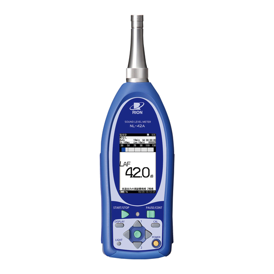
The NL-42A and NL-52A consist of the 1/2-inch electret condenser micro- phone UC-52 (for NL-42A) and UC-59 (for NL-52A), preamplifi er NH-24 (for NL-42A) and NH-25 (for NL-52A), and the main unit. The preamplifi er can be used by separating and extending from the main body. The unit is equipped with the operation keys and 2.8-inch backlit semitransparent color... - Page 20 Up to 1000 measurement results can be stored in the main unit. The NL-42A/NL-52A allows the following quantity measurements. Main processing Simultaneous measurement of all items with selected time weighting (F,...
- Page 21 Outline Additional processing One of the following measurements can be selected for simultaneous processing with main processing. C-weighted equivalent continuous sound level C-weighted peak sound level Cpeak Z-weighted peak sound level Zpeak I-time-weighted equivalent continuous sound level AIeq Takt-max A-weighted sound level Atm5 Maximum I-time-weighted equivalent continuous sound level AImax...
- Page 22 Outline FFT Analysis Program NX-42FT For performing FFT analysis. Once the optional Extended Function Program NX-42EX has been installed, it can no longer be uninstalled.
-
Page 23: Controls And Functions
Controls and Functions Front view Microphone grid Microphone Microphone/ Preamplifier Preamplifier Display Operation key panel Microphone/Preamplifi er The microphone/preamplifi er unit can be detached from the main unit and connected via an optional extension cable. This allows use at a separate location. Be sure to use only the microphone/preamplifi er assembly with the number as shown on the name plate of the unit. - Page 24 Controls and Functions Operation key panel Indicator LED START/STOP key PAUSE/CONT key CAL key DISPLAY key POWER key LIGHT key MENU/ENTER key START/STOP key Press to start or stop the measurement (including the various processing functions). Indicator LED Lights/fl ashes in red or blue to indicate the operation or status of the unit. PAUSE/CONT key During a measurement, this key can be used to exclude unwanted portions from processing.
- Page 25 Controls and Functions MENU/ENTER key Press this key to make or fi nalize the setting of an item in a menu or any other setting. When the key is pressed at the measurement screen, the menu list screen comes up. CAL key (Calibration key) This key is used for calibration of the unit and for level calibration of connected equipment.
-
Page 26: Bottom View
Controls and Functions Bottom view SD card slot DC IN connector DC IN 5-7 V DC OUT AC OUT AC OUT USB connector connector connector Bottom cover (mini B) DC OUT connector Bottom cover This cover protects the connectors on the bottom during transport or storage. Removing the cover gives access to the connectors shown above. -
Page 27: Rear View
Controls and Functions Rear view Seal Model plate Tripod mounting thread Battery compartment Seal The seal guarantees the dustproof and waterproof performance of the unit. Important Note that the unit will not be covered by warranty against dustproof and waterproof performances if the seal is removed. -
Page 28: Preparations
Preparations Power The unit can be powered by four IEC R6, size AA batteries (alkaline), the optional AC adapter NC-98 series, and the optional battery pack BP-21A. Rechargeable nickel metal-hydride batteries may also be used, but the unit does not have a facility for charging the batteries. WARNING If the unit is heated during use or the unit produces smoke or smell of burning, im-... - Page 29 Preparations Inserting the batteries 1. Remove the battery compartment lid as shown below. 2. Insert four IEC LR6, size AA batteries, paying attention to the polarity as indicated in the compartment. 3. Replace the cover. IEC LR6 (size Push the latch in the arrow AA) battery direction and then lift up ×...
- Page 30 Battery life may also be shorter when the program option is operating. Important The rechargeable nickel metal-hydride battery is not charged by the NL-42A/NL-52A. Note The life of rechargeable nickel metal-hydride battery depends on the battery type and charge condition.
- Page 31 Preparations AC adapter To operate the unit with the AC adapter, connect it as shown below. Important To prevent the risk of damage, do not use any AC adapter other than the NC-98 series. The AC adapter NC-34 series used for the conventional sound level meter cannot be used.
-
Page 32: Power On/Off
Preparations Power on/off To turn the unit on Hold down the POWER key until the power-on screen appears (at least 1 second). When the screen is shown, release the POWER key. After the unit has been started, the measurement screen appears. During start up, the indicator LED fl ashes red blue Indicator LED... - Page 33 Preparations Power-on mode switch Opening the battery compartment as shown below gives access to a switch labeled “A-B”. Normally the “A” position is used. Setting this switch to the ''B'' position allows the unit to be turned on simply by supplying power to the DC IN connector.
-
Page 34: Windscreen (Ws-10, Ws-15, Ws-16)
Preparations Windscreen (WS-10, WS-15, WS-16) When making outdoor measurements in windy weather or when measuring air conditioning equipment or similar, wind noise at the microphone can cause measurement errors. Such effects can be reduced by using the windscreen. Mounting the windscreen on the microphone will cause change in frequency response, as shown in the Technical Notes. -
Page 35: Diffuse Sound Fi Eld Correction
Preparations Diffuse sound fi eld correction When using the unit as an ANSI compliant device, set the diffuse fi eld correction to ON. This correction feature is designed to ensure fl at frequency response in a diffuse sound fi eld. 1. -
Page 36: Sd Memory Card And Program Cards
If the SD memory card is removed while data is being read or written to the card, the data may be destroyed. Use SD memory cards provided by Rion. The performance of other cards is not guaranteed. Note that we assume no responsibility for any damage or loss of stored measurement data. -
Page 37: Microphone Extension Cables (Ec-04 Series)
Preparations Microphone extension cables (EC-04 series) Be sure to turn power to the unit OFF before separating the microphone from the main unit. To reduce measurement deviations due to refraction effects and the acoustic infl uence of the operator, the microphone can be detached from the unit and connected via an extension cable. - Page 38 Preparations 2. Connect the extension cable to the preamplifi er and to the main unit and fasten the connectors with the fastening screw. 3. When mounting the microphone on a tripod, fi rst fasten the microphone holder (supplied with the extension cable) to the tripod. Then insert the extension cable connector into the microphone holder.
-
Page 39: Tripod Mounting
Preparations Tripod mounting For long-term measurements, the unit can be mounted on a camera tripod. Caution Proceed carefully, to avoid dropping the unit or tipping over the tripod. When using the tripod, ensure that it is stable with the unit mounted on it. Do not carry the unit with the tripod attached. -
Page 40: Connection To A Printer (Dpu-414)
Preparations Connection to a printer (DPU-414) Connect the I/O connector on the bottom of the NL-42A/NL-52A with an input connector of a printer DPU-414, using the printer cable CC-42P as shown below. The performance of other cables is not guaranteed. - Page 41 A printout showing the current status of the printer is produced. An example showing suitable software DIP switch settings for use of the printer with the NL-42A/NL-52A is shown below. (The actual printout will be in a different font.) [DIP SW setting mode]...
-
Page 42: Connection To A Level Recorder (Lr-07, Lr-20A) And Data Recorder (Da-20, Da-21, Da-40)
Connection to a level recorder (LR-07, LR-20A) and data recorder (DA-20, DA-21, DA-40) Connect the AC OUT connector on the bottom of the NL-42A/NL-52A with an input connector of level recorder (LR-07, LR-20A) and data recorder (DA-20, DA-21, DA-40), using the optional BNC - Pin output code CC-24 as shown below. -
Page 43: Connection To A Computer
Preparations Connection to a computer Connect the USB connector on the bottom of the NL-42A/NL-52A with a USB connector of a computer, using the optional (generic) A - mini B USB cable as shown below. An SD memory card inserted in the unit will be recognized as a removable disk by the computer when connected via USB, without having to install a USB driver. -
Page 44: Setting The Date And Time
Preparations Setting the date and time The unit incorporates a clock which allows recording the date and time along with measurement data. Set the date and time as described below. 1. Press the MENU/ENTER key to bring up the menu list screen. 2. -
Page 45: Measurement In A Dark Location
Preparations Measurement in a dark location Pressing the LIGHT key will turn on the display backlight, for easier reading in a dark location. The backlight operation pattern can be controlled via a menu, as follows. 1. Press the MENU/ENTER key to bring up the menu list screen. 2. - Page 46 Preparations Backlight/LCD System screen settings screen...
-
Page 47: Sub Channel Settings
Preparations Sub channel settings When the sub channel is set to ON, the sound level will be shown using the frequency weighting and time weighting settings made for the sub channel, along with the main channel sound level display. To use the sub channel, you must make certain settings on a menu screen. 1. - Page 48 Preparations Note If the sub channel is not set to “ON”, measurement value are not displayed. Since the sound level data of sub channel is not saved, it will not be displayed on the recall screen (see pages 67 and 90). When the optional Extended Function Program NX- 42EX is not installed, the time weighting characteristic I (Impulse) cannot be selected.
- Page 49 Preparations Additional processing When the [Sub Channel Settings] is set to ON, one of the following items can be measured with main channel as simultaneous measurement function (see page 80). C-weighted equivalent continuous sound level C-weighted peak sound level Cpeak Z-weighted peak sound level Zpeak I-time-weighted equivalent continuous sound level...
-
Page 50: Eco Setting (Power-Saving Mode)
Preparations Eco setting (Power-saving mode) The Eco setting enables the power saving feature. A long-time measurement can be performed using batteries only. 1. Press the MENU/ENTER key to bring up the menu list screen. 2. Use the keys to select [System (Language)] and press the MENU/ENTER key. -
Page 51: Comparator Output
Preparations Comparator output This is an open collector output that can be used to control external equipment. When the optional Extended Function Program NX-42EX is not installed, the comparator output cannot be set. 1. Press the MENU key to bring up the menu list screen. 2. - Page 52 Comparator screen Connecting external equipment Connect the I/O connector on the bottom of the NL-42A/NL-52A with an input connector of external equipment, using the optional comparator output cable CC-42C as shown below. The performance of other cables is not guaranteed.
- Page 53 Preparations About the comparator output When the sub channel is OFF, the comparator will not function if sub channel (SUB AP) is selected as comparator band. The comparator signal output timing pattern is as shown below. Comparator output Comparator signal output continues for 1 second after signal crosses level threshold Comparator level...
-
Page 54: Language Selection
Preparations Language selection The language used for displaying messages and menus can be selected as follows. 1. Press the MENU/ENTER key to bring up the menu list screen. 2. Use the keys to select [System (Language)] and press the MENU/ENTER key. The system screen appears. 3. -
Page 55: Calibration
Calibration Before starting a measurement, the unit must be calibrated. There are two types of calibration, namely electrical calibration using an internally generated signal and acoustic calibration using an external sound calibrator. Internal calibration (Electrical calibration) Calibration is carried out using a signal generator (1 kHz, sinusoidal wave) built into the unit. - Page 56 Calibration 4. When calibration to 124.0 dB is completed, press the CAL key once more to return to the measurement screen. Note If the bar graph upper limit setting is not 130 dB, bring the level indication to a value that is 6 dB below the upper limit of the bar graph scale.
-
Page 57: Acoustic Calibration (With Sound Calibrator Nc-75/Nc-74 Or Pistonphone Nc-72B/Nc-72A)
Z or C. For acoustic calibration, a sound calibrator or a pistonphone is mounted to the microphone of the NL-42A/NL-52A, and adjustment is performed so that the reading of the meter is equal to the sound pressure level inside the coupler. - Page 58 If “Internal Calibration” is shown in the upper part of the screen, press the DISPLAY key. The calibration mode will change to “Acoustic Calibration”. 6. Use the keys to adjust the reading of the NL-42A/NL-52A to the value shown below. When using NC-75/NC-74: NL-42A: 93.9 dB NL-52A: 94.0 dB...
-
Page 59: Reading The Display
Reading the Display Measurement screen display The illustration below shows all elements of the display for explanation pur- poses. In actual operation, such a screen will not be shown. Diffuse sound field correction Back-erase function Mode of analysis SD memory card insertion indicator Windscreen correction SD memory card remaining capacity Delay time... - Page 60 Reading the Display SD memory card remaining capacity Shows the remaining capacity of an inserted SD memory card. Delay time Shows the delayed measurement time set by “Delay Time” (see page 75). Operation/measurement elapsed time Shows the elapsed time from the start of measurement. Address Shows the current memory address.
- Page 61 Reading the Display Overload indication When a sound level overload condition is detected, the indication (white on red) is shown for at least 1 second. If processed data contain signal overload data, the indication shown. This indication remains on the processed data display screen until the next processing measurement is started.
- Page 62 Reading the Display Current date and time Shows the current date and time. Backlight Indicates that the display backlight has been lit up (see page 27). Touch panel lock Indicates that the touch panel lock function has been set to ON. Touch panel operations are disabled while this symbol is displayed (see page 53).
- Page 63 Reading the Display Time weighting Indicates the main channel time weighting characteristic. F: Fast, S: Slow Under-range indication When a signal under-range condition is detected, the indication (white on black) is shown. If processed data contain signal under-range data, the indication is shown.
-
Page 64: Sub Channel Display Screen
Reading the Display Sub channel display screen The sub channel L value can be displayed on the measurement screen by setting [Sub Channel Settings] to ON on the [Measure] screen from the menu (see page 29). Main channel value display Sub channel value display Processed data display screen other than L... -
Page 65: Time-Level Screen
Reading the Display Time-Level screen While [Time-Level] is set to ON on the [Display] screen from the menu, the time-level screen will be displayed by pressing the DISPLAY key on the measurement screen (see page 55). -
Page 66: Indicator Messages
Reading the Display Indicator messages When keys such as START/STOP or PAUSE/CONT are pressed, indicator messages such as shown below will appear on the display for about 1 second. When START/STOP key was pressed and processing has started When START/STOP key was pressed and processing has ended When PAUSE/CONT key was pressed and operation is paused... -
Page 67: Menu List Screen
Reading the Display Menu list screen When the measurement screen is displayed, pressing the MENU/ENTER key brings up the menu list screen as shown below. Use the keys to select the desired menu and press the MENU/ ENTER key. Pressing the DISPLAY key displays explanation screen of the item that has been selected. - Page 68 Reading the Display The following settings of frequency weighting, time weighting and sub channel measurement ON/OFF can be done with the touch panel. (The current setting is shown when the menu list screen is displayed.) Touch the screen directly with your fi nger. Freq Selects the frequency weighting characteristic for the main channel.
-
Page 69: System (Language)
Reading the Display System (Language) This screen sets the item concerning the system of the unit. Use the keys to select [System (Language)] and press the MENU/ ENTER key. The system screen appears. Each item of the system screen is selected using the key. - Page 70 Reading the Display Backlight/LCD Settings Displays the screen to set the function of the backlight and the LCD of the unit. Select [Backlight/LCD Settings] and press the MENU/ENTER key. The backlight/LCD settings screen appears (see page 27). Battery Type Displays the screen to select the type of battery used for the unit. The battery power corresponding to the selected battery is displayed on the measurement screen.
- Page 71 Reading the Display Index Displays the screen to set the identifi cation number of the unit when multiple units are used in a parallel measurement. Select [Index] and press the MENU/ENTER key. The index screen appears. Use the keys to select the digit, and use the keys to set the value (1 to 255).
-
Page 72: Display
Reading the Display Display This screen sets the measurement values displayed on the measurement screen. Use the keys to select [Display] and press the MENU/ENTER key. The display screen appears. Each item of the display screen is selected using the key. -
Page 73: Output Level Range Upper
Reading the Display LN1, LN2, LN3, LN4, LN5 Displays the screen to select the percentile sound level displayed on the measurement screen. To set the L1 to L99 value for LN1 to LN5, use the keys to change the value (only LN5 can be set the value from L0.1 to L99.9.). Select the percentile sound level (LN1 to LN5) and press the MENU/ ENTER key. -
Page 74: Output Level Range Lower
Reading the Display Output Level Range Lower Displays the screen to set the lower bound value of the bar graph on the measurement screen. Select [Output Level Range Lower] and press the MENU/ENTER key. The lower limit of bar graph screen appears. Use the keys to set the value (20 to 80, 10 dB step). -
Page 75: I/O
Reading the Display This screen sets the type of output signal etc. Use the keys to select [I/O] and press the MENU/ENTER key. The I/O screen appears. Each item of the I/O screen is selected using the key. Pressing the DISPLAY key displays explanation screen of the item that has been selected. - Page 76 Reading the Display DC OUT Displays the screen to select the DC signal output from the DC OUT connector of the unit. Select [DC OUT] and press the MENU/ENTER key. The DC OUT setting screen appears (see page 108). Use the keys to select the DC signal output (OFF or MAIN) and press the MENU/ENTER key.
-
Page 77: Store
Reading the Display Store This screen sets the mode that stores the operation result data. Use the keys to select [Store] and press the MENU/ENTER key. The store screen appears. Each item of the store screen is selected using the key. - Page 78 Reading the Display Store Name (common to each mode) Displays the screen to set the identifi cation number of the store data. (0000 to 9999) Select [Store Name] and press the MENU/ENTER key. The store name screen appears. The store name cannot be set in manual mode when an SD card is not inserted.
- Page 79 Reading the Display Start (Timer Auto mode) Displays the screen to set the measurement start time in the Timer Auto mode. Select [Start] and press the MENU/ENTER key. The start time setting screen appears. When the start time setting screen is displayed for the fi rst time, current time is indicated.
-
Page 80: Measure
Reading the Display Measure This screen sets the correction of the measurement etc. Use the keys to select [Measure] and press the MENU/ENTER key. The measurement setting screen appears. Each item of the measurement setting screen is selected using the key. -
Page 81: Back Erase
Reading the Display Time Weighting (Main) Displays the screen to select the time weighting characteristics for the main channel. Select [Time Weighting (Main)] and press the MENU/ENTER key. The time weighting screen appears. Use the keys to select the time weighting characteristics (F [Fast], S [Slow]) and press the MENU/ENTER key. -
Page 82: Ln Mode
Reading the Display LN Mode Displays the screen to select calculation date for percentile sound level L Select [LN Mode] and press the MENU/ENTER key. The LN mode screen appears. Use the keys to select the calculation date (Lp, Leq,1s) and press the MENU/ENTER key. -
Page 83: Save/Print
Reading the Display Save/Print The measurement data or recall data displayed on the screen can be saved or printed on the save/print screen. Use the keys to select [Save/Print] and press the MENU/ENTER key. The save/print screen appears. Each item of the save/print screen is selected using the key. - Page 84 Select a desired program name to switch the function. Select the program name to be used and press the MENU/ENTER key. Either NL-42A or NL-52A is displayed depending on the model used. Program names which are not installed will not be displayed.
-
Page 85: Recall
If a data fi le saved on a computer is copied or manip- ulated, and the copied fi le is then loaded back into the NL-42A/NL-52A, the displayed measurement date and time may not match the actual time stamp of the measurement. - Page 86 Reading the Display Select data fi le and press the MENU/ENTER key. The fi le processing screen appears. Confi rm the data Displays the measurement data of the selected data fi le. Select [Confi rm the data] and press the MENU/ENTER key. You can use the keys to display data stored at higher or lower address numbers.
- Page 87 Reading the Display Delete the data Deletes the selected data fi le. Select [Delete the data] and press the MENU/ENTER key. The confi rmation screen appears. Use the keys to select [Yes] and press the MENU/ENTER key. Copy to the card (only internal memory data) Copies the selected internal memory data fi le to the inserted SD memory card.
- Page 88 Reading the Display Select this screen to record the waveform using optional program NX-42WR. If NX-42WR is not installed, it is not possible to select this screen. For details, please refer to the instruction manual of Waveform Recording Program NX-42WR.
-
Page 89: Menu List Items
Reading the Display MENU list items System (Language) Read/Save Settings [v]---------- Load Default Settings Internal Memory---- List of setting groups on internal memory Startup File SD---- List of setting groups on SD memory card Clock Settings Backlight/LCD Settings [v]-----Backlight Auto Off Backlight brightness LCD Auto Off (Auto Store) Battery Type---- Alkaline/Ni-MH... -
Page 90: Measurement
Measurement When using the unit in a mode other than “sound level measurement”, all processing functions provided by the unit (L ) are carried out simultaneously. (However, for the sub channel, only the additional processing function set to “ON” in the menu list screen is carried out.) For example, when equivalent continuous sound level measurement is selected, the sound exposure level and percentile sound level are also determined. - Page 91 Measurement 2. Press the MENU/ENTER key and select the frequency weighting characteristic on the menu list screen. For normal sound level measurements, select the “A” setting. When Z is selected, the sound pressure level from 10 Hz to 20 kHz is measured with fl at characteristics.
-
Page 92: Equivalent Continuous Sound Level (L Eq ) Measurement
Measurement Equivalent continuous sound level (L ) measurement The procedure for equivalent continuous sound level measurement is described below. Preparations as described in the “Preparations” chapter must be completed fi rst. 1. Turn power to the unit on. 2. Press the MENU/ENTER key and select the frequency weighting characteristic on the menu list screen. - Page 93 Measurement 7. Use the keys to select [ON] and press the MENU/ENTER key. Press the PAUSE/CONT key to return to the menu list screen. 8. For information about how to store data, refer to the section starting (see page 85). 9.
- Page 94 Measurement 16. Use the keys to select the delayed measurement time (OFF, 1s [second], 3s, 5s, 10s) and press the MENU/ENTER key. Press the PAUSE/CONT key to return to the menu list screen. Measurement start START/STOP key pressed Preset delayed time measurement time Time...
- Page 95 Measurement 21. Press the START/STOP key to start the measurement. At this point, previous measurement values are cleared. While the measurement is in progress, the symbol fl ashes and the elapsed time is displayed. In addition, the indicator LED fl ashes red. When the measurement time set in step 13 has elapsed, the measure- ment is terminated automatically.
-
Page 96: Off
Measurement Data excluded by back-erase function (ON, 5 s) Time-Level screen Note If any or several of the following conditions apply, the back-erase function will not be available. - Waveform Recording Program NX-42WR is installed and Wave Rec Mode is set to a setting other than “OFF”. - “L ”... -
Page 97: Measurement
Measurement Sound exposure level (L ), Maximum sound level (L Minimum sound level (L ) and Percentile sound level (L measurement The sound exposure level (L ), maximum sound level (L ), minimum sound level (L ) and percentile sound level (L ) are all measured at the same time as the equivalent continuous sound level (L When the equivalent continuous sound level is measured with desired... -
Page 98: Additional Processing Value Measurement
Measurement Additional processing value measurement When the sub channel is ON, one of the following processing functions is available in addition to L , and L C-weighted equivalent continuous sound level C-weighted peak sound level Cpeak Z-weighted peak sound level Zpeak I-time-weighted equivalent continuous sound level AIeq... - Page 99 Measurement Settable measurement value of additional processing The measurement value that can be set by the additional processing is different according to the sub channel settings. The relation between settable measurement value of additional processing and the sub channel setting is as follows. Sub channel settings Measurement value Measurement values of...
- Page 100 Measurement Additional processing value setting procedure Set the sub channel according to the desired additional processing beforehand (see page 29). 1. Press the MENU/ENTER key to bring up the menu list screen. 2. Use the keys to select [Measure] and press the MENU/ ENTER key.
-
Page 101: Card Capacity And Store Time
Card capacity and store time The measurement duration for which data can be stored on an SD memory card depends on the capacity of the inserted card. Approximate times are listed below. Using Auto store (when the NX-42EX is installed) Only L store interval set SD memory card capacity... -
Page 102: When Performing Waveform Recording (When The Nx-42Wr Is Installed)
Card capacity and store time When performing waveform recording (when the NX- 42WR is installed) Using Auto store, 16 bit, L store interval 100 ms SD memory card capacity 512 MB 2 GB 32 GB 48 k 1 hour 4 hours 40 min. 74 hours 40 min. -
Page 103: Store Operation
Store Operation The NL-42A/NL-52A can store measurement data (processed data such as sound level and equivalent continuous sound level, and measurement param- eters such as frequency weighting and time weighting characteristics) in the internal memory or on SD memory card. - Page 104 Store Operation Auto (only when the NX-42EX is installed) The processing result which is obtained using the selected sound level and specifi ed interval by the store interval setting will be recorded continuously. When the following one of conditions occurred, the store is stopped and data is saved.
- Page 105 Since AS-60 cannot read Manual store data, perform measurement with Auto or Timer Auto store to handle measurement data using AS-60. When setting the L • Store Interval to 200 ms or 1s on the NL-42A/ NL-52A, the AS-60 software calculates the maximum L as L the minimum L as L from within the measured period.
-
Page 106: Manual Mode Operation
Store Operation Manual mode operation Memory store When an operator performs store operation on the confi rmation screen dis- played after processing fi nishes, each processed data will be stored. If no SD memory card is inserted, the data will be stored in the internal memory of the unit. - Page 107 Store Operation 6. Specify the store name (number of four digits: when SD memory card is inserted). 6-1. Use the keys to select [Store Name] and press the MENU/ ENTER key. The store name screen appears. 6-2. Use the keys to select the fi rst two digits, and use the keys to set the value.
- Page 108 Store Operation 10. Start a measurement. When it fi nishes, a confi rmation screen will be displayed. Select “Store data” and press the MENU/ENTER key to store the processing results. The store process takes about 1 second. When it is completed, the address is incremented by one step.
- Page 109 Store Operation Deleting stored data The procedure for deleting data stored in memory using Manual mode is described below. Note Data are deleted in store name units. It is not possible to selectively delete data for a specifi c address. 1.
-
Page 110: Auto Mode Operation
Store Operation Auto mode operation Memory store The optional Extended Function Program NX-42EX should be installed. An SD memory card should be inserted. With the Auto mode, L store and L store are executed simultaneously (separate operation also possible). The procedure for storing data using Auto mode is as follows. Confi rm the SD memory card has been inserted in the card slot. - Page 111 Store Operation 6. Specify the store name. 6-1. Use the keys to select [Store name] and press the MENU/ ENTER key. The store name screen appears. 6-2. Use the keys to select the fi rst two digits, and use the keys to set the value.
- Page 112 Store Operation keys to select the L 9-2. Use the calculation interval (OFF, 10s, 1min, 5min, 10min, 15min, 30min, 1h, 8h, 24h, Manual) and press the MENU/ENTER key. If the L calculation interval set to OFF, L is not stored. 9-3.
-
Page 113: Marker
Store Operation Marker When the store mode is set to Auto or Timer Auto, and the L store interval is specifi ed, a marker can be added to the data. 1. Select [Store] from the menu list screen and set the store mode to Auto or Timer Auto. - Page 114 Store Operation Recalling stored data The procedure for recalling data stored in memory using Auto mode is de- scribed below. 1. Press the MENU/ENTER key to bring up the menu list screen. 2. Use the keys to select [Recall] and press the MENU/ ENTER key.
-
Page 115: Timer Auto Mode Operation
Store Operation Timer Auto mode operation Memory store The optional Extended Function Program NX-42EX should be installed. An SD memory card should be inserted. With the Timer Auto mode, L store and L store are executed simultaneously (separate operation also possible). The procedure for storing data using Timer Auto mode is as follows. - Page 116 Store Operation 6. Specify the store name. 6-1. Use the keys to select [Store Name] and press the MENU/ ENTER key. The store name screen appears. 6-2. Use the keys to select the fi rst two digits, and use the keys to set the value.
- Page 117 Store Operation 9. Set the start time. The measurement is started at the preset start time. 9-1. Use the keys to select [Start] and press the MENU/ENTER key. The start time setting screen appears. When the start time set- ting screen is displayed for the fi rst time, current time is indicated. 9-2.
- Page 118 Store Operation When timer auto interval is set Measurement time (actual measurement time) Measurement time (actual measurement time) set as L set as L calculation interval calculation interval Data saved Data saved Measurement in address 1 in address 1 start Measurement Measurement Standby...
- Page 119 Store Operation Note Relationship between elapsed measurement time and number of data When using Timer Auto mode and 100-ms sampling, 10 data sets are stored per second. Therefore, when 10 seconds of measurement time have elapsed, the number of stored data is 100 (10 when using 1-second sampling).
-
Page 120: Data Size Information
The memory cards that can be used in this unit are SD memory cards. Be sure to use optional SD memory cards provided by Rion. SD memory cards even from the same manufacturer and of the same type exhibit certain varia- tions in specifi cations which may cause problems. - Page 121 If measurement data in the SD memory card is moved to a computer and then moved back to NL-42A/ NL-52A, the measurement date (time stamp) may be different from the actual date.
-
Page 122: Formatting An Sd Memory Card
In the following cases, you should format the SD memory card: • When using the SD memory card in the NL-42A/NL-52A for the fi rst time • When wishing to delete all data from the SD memory card To format an SD memory card, proceed as follows. -
Page 123: Screen Hard Copy
Store Operation Screen hard copy When you press the key of keys while holding down the DISPLAY key, the “Screenshot was saved to the card” message is displayed and the current screen contents will be saved as a bitmap fi le on the SD memory card. -
Page 124: Input/Output Connectors
Input/Output Connectors AC OUT connector Set the frequency weighting characteristic of the signal output from the AC OUT connector of the unit. 1. Press the MENU/ENTER key to bring up the menu list screen. 2. Use the keys to select [I/O] and press the MENU/ENTER key. - Page 125 Input/Output Connectors The relationship between the display value shown by the unit and the output voltage is indicated below. When the unit is set to the calibration mode, the output signal (output level range upper 120 dB − 6 dB = 114 dB, 1000 Hz sinusoidal wave) is 0.5 Vrms.
-
Page 126: Dc Out Connector
Input/Output Connectors DC OUT connector Set the frequency weighting characteristic of the signal output from the DC OUT connector of the unit. 1. Press the MENU/ENTER key to bring up the menu list screen. 2. Use the keys to select [I/O] and press the MENU/EN- TER key. - Page 127 Input/Output Connectors The relationship between the display value shown by the unit and the output voltage is indicated below. When the unit is set to the calibration mode, the output signal (output level range upper 120 dB − 6 dB = 114 dB) is 2.35 V. −110 −100 −90 −80...
-
Page 128: I/O Connector
Input/Output Connectors I/O connector The I/O connector is located at the bottom of the unit and used for RS-232C communication or comparator output. To use this connector for RS-232C communication and connect to a printer, see page 22. For comparator output, see page 33. Note The RS-232C communication and the comparator output cannot be used at the same time. -
Page 129: Default Settings
Default Settings The factory default settings of the unit are listed below. Main channel frequency weighting ....A Main channel time weighting ......F(Fast) Output level range upper ........130 dB Output level range lower ........30 dB Calibration mode ..........Internal Back erase ............ - Page 130 Default Settings Comparator (NX-42EX)........OFF Communication interface ......... OFF Baud rate ............9600 bps Backlight auto off ..........30 s Backlight brightness ........2 LCD auto off at auto store ........ OFF Index ..............1 Battery type ............. Alkaline Touch panel lock ..........OFF When you turn power to the unit on while holding down the START/STOP key, the unit will be initialized to the above settings.
-
Page 131: Setup Files
Setup Files Resume function When power to the unit is turned on, the measurement screen appears. The settings active at this point are the same as were selected before the unit was last turned off (resume function). Note When the unit is started while a start up fi le exists in the internal memory and SD memory card, the start up fi le load function (see the following description) will be executed fi rst. -
Page 132: Restoring Default Settings (Factory Default Settings)
Setup Files Restoring default settings (factory default settings) Follow the steps below to restore the default settings. 1. Use the keys to select [System (Language)] and press the MENU/ENTER key. The system screen appears. 2. Use the keys to select [Read/Save setting] and press the MENU/ ENTER key. -
Page 133: Using Setup Fi Les
Setup Files Using setup fi les Setup fi les enable the following functions. • Establish settings quickly and precisely by loading from a fi le prepared beforehand and stored on internal memory or SD memory card • Return settings that were accidentally changed to the previous condition by loading from a fi le stored on internal memory or SD memory card Setup fi les can be saved up to fi ve in the internal memory of the unit and up to fi ve in an SD memory card. - Page 134 Setup Files Loading a setup fi le Note When you load settings from a fi le, the current settings will be overwritten. If necessary, you should save the current settings before loading a new set of settings. 1. Use the keys to select [System (Language)] and press the MENU/ENTER key.
- Page 135 Setup Files Copying a setup fi le 1. Use the keys to select [System (Language)] and press the MENU/ENTER key. The system screen appears. 2. Use the keys to select [Read/Save setting] and press the MENU/ ENTER key. The setting operation screen appears. 3.
-
Page 136: Setting A Start Up Fi Le
Setup Files Setting a start up fi le When a setting is saved in a start up fi le, the unit can be started using the setting. 1. Set the unit to the intended condition, so that measurement param- eters and other settings are as desired. 2. -
Page 137: Optional Accessories
Optional Accessories Microphone extension cables (EC-04 series) For enhanced measurement accuracy, the microphone can be detached from the unit and connected via an extension cable. This will reduce measurement deviations due to refraction effects of the unit or the acoustic infl uence of the operator. -
Page 138: Printer Dpu-414
Optional Accessories Printer DPU-414 Data stored in the memory of the unit and on SD memory card can be printed out on a printer. You can also produce hard copy of measurement screens. To print measurement data, turn the unit and the printer on and set the printer to the online state. - Page 139 Optional Accessories Printing stored data The steps for printing hard copy of a stored data are described below. 1. Press the MENU/ENTER key to bring up the menu list screen. 2. Use the keys to select [Recall] and press the MENU/ ENTER key.
- Page 140 Optional Accessories 6. Use the keys to select [Save/Print] and press the MENU/ ENTER key. The save/print screen appears. 7. Use the keys to select [Range Setting Print] and press the MENU/ENTER key. The range setting print screen appears. 8. Set the [Start Addr.] and [End Addr.] and then select [Print Execution] and press the ENTER key.
-
Page 141: Level Recorder Lr-07/Lr-20A
Sound level recording The procedure for recording sound level changes over time is described be- low. Turn power to the NL-42A/NL-52A and the level recorder on. The steps described in the chapter “Preparations” (page 10) should be completed. For details about level recorder operation, refer to the documentation supplied with the level recorder. - Page 142 Optional Accessories 8. Press the CAL key once more to return the NL-42A/NL-52A to the measurement mode. 9. Set the time weighting characteristic at the level recorder. 10. Set the [Output Level Range Upper] and [Output Level Range Lower] on the [Display] screen.
-
Page 143: Program Options
Optional Accessories Program options The unit can make use of a range of program options. For details on usage, refer to the documentation supplied with the respective program. Note Once the Extended Function Program NX-42EX has been installed, it can no longer be uninstalled. -
Page 144: Specifi Cations
IEC 61672-1:2013/2002 class 1 ANSI/ASA S1.4-2014/Part 1 class 1 JIS C 1509-1:2017 class 1 JIS C 1516:2020 class 1 NL-42A/NL-52A CE marking, UKCA marking, China RoHS KC mark Measurement function Simultaneous measurement of all items, using selected time weighting and frequency weighting... - Page 145 5 min, 10 min, 15 min, 30 min, 1 h, 8 h, 24 h and manually selected arbitrary time. Arbitrary period of time up to 24 h can be set manually. When Auto store mode is selected, up to 1000 hours can be set. Microphone NL-42A NL-52A Model: UC-52 UC-59 Sensitivity: −33 dB...
- Page 146 25 dB to 138 dB (A-weighting, 1 kHz) Linear operating range All-pass (A-weighting) 113 dB Measurement frequency range 20 Hz to 8 kHz (NL-42A) 10 Hz to 20 kHz (NL-52A) Reference frequency 1 kHz Reference sound pressure level 94 dB...
- Page 147 Internal calibration Electrical calibration with signal from built-in oscillator (1 kHz, [scale upper limit of the bar graph] − 6 dB) Acoustic calibration NC-75/NC-74 (1 kHz, 93.9 dB [NL-42A] / 94.0 dB [NL-52A]) NC-72B/NC-72A (250 Hz, 114.0 dB) Correction functions...
-
Page 148: Measurement Time
1 sec to 24 hours Data store capacity Up to 1000 data sets in the internal memory External memory depends on the SD memory card capacity (only the performance of Rion genuine cards is guaranteed). Data recall Allows viewing of store data. - Page 149 Specifi cations DC/AC simultaneous output Enables simultaneous output of DC output and AC output. Overload Characteristics / Under-Range OVER is displayed when the input level is 138.3 dB or higher at all-pass level. OUTPUT OVER is displayed at +8.3 dB or higher above the indicated upper range when AC or DC output is available.
- Page 150 Specifi cations Power requirements Four AA batteries or external power supply Battery life (at 23°C): Alkaline batteries LR6: Approx. 26 hours Ni-MH secondary batteries: Approx. 25 hours (Depending on the manufacturer) Battery life varies depending on the setting of this unit. AC adapter NC-98 series External DC power supply...
- Page 151 Specifi cations Optional accessories SD Card 512 MB MC-51SD1 SD Card 2 GB MC-20SD2 SD Card 32 GB MC-32SP3 AC adapter (100 V to 240 V) NC-98 series Battery pack BP-21A Microphone extension cable EC-04 series All-Weather Windscreen WS-15 Mounting adapter for windscreen WS15006 Rain-protection Windscreen WS-16...
- Page 152 Specifi cations Front view Side view Rear view Bottom view Unit: mm Dimensional Drawings...
- Page 154 No. 66301 22-05...
Need help?
Do you have a question about the NL-42A and is the answer not in the manual?
Questions and answers