
Related Manuals for Rion NA-83


Summary of Contents for Rion NA-83
-
Page 1: Sound Level Meter
INSTRUCTION MANUAL SOUND LEVEL METER NA-83 3-20-41 Higashimotomachi, Kokubunji, Tokyo 185-8533, Japan http://www.rion.co.jp/english/... - Page 3 This manual describes the features, operation and other aspects of the Sound Level Meter NA-83. If the unit is used together with other equipment to confi gure a mea- surement system, consult the documentation of all other components as well. The following pages contain important information about safety.
- Page 4 Technical Reference Provides information about the confi guration of the unit, electrical and acoustic specifi cations, IEC compliance, and other items. Specifi cations Lists the technical specifi cations of the unit. Serial Interface Transfer Format and Protocol Provides information about connection to a computer, and the procedures for command reception and data transfer.
-
Page 5: For Safety
FOR SAFETY In this manual, important safety instructions are specially marked as shown below. To prevent the severe damage to the unit or peripheral equipment, make sure that all instructions are fully understood and observed. Important D isrega rd i ng i nst r uct ions printed here incurs the risk of damage to the product. - Page 6 Precautions Operate the unit only as described in this manual. The NA-83 is a precision instrument. Protect it from shocks and vibra- tions. Take special care not to touch the microphone diaphragm. The diaphragm is a very thin metal fi lm which can easily be damaged.
- Page 7 The product described in this manual is in conformity with the following standards; EN61326-1:2006/IEC 61326-1:2005 Electrical equipment for measurement control and laboratory use. RION Co., Ltd. 3-20-41 Higashimotomachi, Kokubunji, Tokyo 185-8533, Japan RION Co., Ltd. Europe Representative Offi ce Schaepmanlaan 66, 4623 XZ, Bergen op Zoom, The Netherlands...
-
Page 8: Table Of Contents
Contents FOR SAFETY ..................iii Outline ....................1 Controls and Functions ................2 Front panel ..................2 Right side panel .................3 Left side panel ...................5 Rear panel ..................6 Display panel ..................7 Outdoor Microphone MS-11 ............10 Connections ..................11 Using the All-Weather Windscreen WS-13 ........11 Microphone connection .............. - Page 9 Measurement ...................33 Measurement of time-weighted sound level L (instantaneous value) .33 Measurement of maximum time-weighted sound level L ....35 Connectors ....................37 MIC. IN connector ................37 Rear-panel connector .................38 Wiring diagram ..................39 DC power supply ................. 40 Reset control ................40 Default Values ..................41 Technical Reference .................42 Microphone and Preamplifi er .............42...
- Page 10 Serial Interface Transfer Format and Protocol ..............80 Transfer protocol ................80 Local Mode/Remote Mode ..............80 Transfer codes .................. 81 Transfer format ................82 Block reception processing ............83 Communication cutoff ..............88 Ratings ....................88 Commands .....................89 Command list ...................89 Command format ................90 Error codes ..................91 Command send example ..............
-
Page 11: Outline
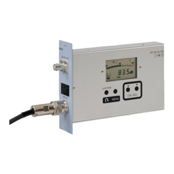
Outline The NA-83 is a Sound Level Meter that conforms to Measurement Law re- quirements for precision sound level meters, IEC 61672-1:2002 Class 1 (JIS C 1509-1:2005 Class 1). It features a wide measurement range for sound levels from 28 dB to 138 dB without range switching. Measurement values are displayed on the integrated LCD panel. -
Page 12: Controls And Functions
Controls and Functions Front panel NA-83 AC/DC OUT AC/DC OUT connector Serial number plate AC/DC OUT connector cap MIC. IN MIC. IN connector AC/DC OUT connector Supplies either an AC or DC output signal (selectable). For details on the AC/DC OUT setup screen, see page 26. -
Page 13: Right Side Panel
Controls and Functions Right side panel Display DC IN 10- 15V Fast Lp/Lmax CAL ADJ. MENU MENU key CAL ADJ. keys Determines whether sound level measurement is for instantaneous value or maximum hold value. When a menu screen has been called up with the MENU key, the key serves for selecting a setting item. - Page 14 Controls and Functions CAL ADJ. keys When the “Calibration/operation check with microphone integrated sound source” screen and “Calibration with external sound calibrator” screen is used, these keys serve to adjust the calibration level. When another menu screen is shown, the keys serve for returning to the measurement screen.
-
Page 15: Left Side Panel
Controls and Functions Left side panel SOUND LEVEL METER MODEL NA- 83 SER.NO. MICROPHONE MS- 11 IEC 61672 - 1:2002 Class 1 MADE IN JAPAN Name plate Name plate Shows information about the model name, type, serial number, micro- phone serial number, standard compliance, etc. -
Page 16: Rear Panel
Controls and Functions Rear panel Power supply connector Connector cover plate (for rear-panel connector) Power supply connector A DC source rated for 10 to 15 V can be connected here. The AC adapter RC45-12L should be used. Connector cover plate Protects the rear-panel connector. -
Page 17: Display Panel
Controls and Functions Display panel Windscreen Microphone integrated correction sound source indicator frequency indicator AC/DC OUT Maximum value CAL indicator MS-11 indicator indicator measurement indicator Bar graph Over Over Under Under-range Over-range indicator indicators Fast Slow Power supply voltage indicator Frequency weighting Time weighting Numeric readout... - Page 18 Controls and Functions Microphone integrated sound source frequency indicator When “Calibration with microphone integrated sound source” or “Op- eration check with microphone integrated sound source” is carried out, the frequency of the integrated sound source is shown here. The follow- ing four indications are available.
- Page 19 Controls and Functions Power supply voltage indicator Shows the voltage of the power supplied to the unit, as follows. ] (2 segments on): approx. 11.3 to 15 V ] (1 segment on): approx. 9.8 to 11.3 V ] (fl ashing): lower than approx.
-
Page 20: Outdoor Microphone Ms-11
Integrated sound source This source is driven by a signal from the NA-83 and generates a cali- bration tone (1 kHz, 114 dB, at an atmospheric pressure of 101.3 kPa) within the microphone cartridge. It can be used to calibrate and verify operation of the system consisting of the microphone and sound level meter. -
Page 21: Connections
Connections Using the All-Weather Windscreen WS-13 Important Disconnect the power before making any con- nections (see page 21). Use only the microphone whose serial number is shown on the name plate of the unit. The All-Weather Windscreen WS-13 and Microphone Extension Cable EC- 04 series are sold separately as options. - Page 22 Connections 3. Pass the lower part of the insulation attachment onto the fl ange sec- tion of the MS-11. The insulation attachment is not yet fi xed at this point. Lower part of insulation attachment Flange section MS-11 Pass onto flange 4.
- Page 23 Connections (Attaching the windscreen) (If windscreen and inner cap are to be reattached after replacing these parts, perform steps 7 to 9.) 6. The windscreen is shipped from the factory with the base and inner cap attached. Insert the MS-11 directly into the assembly and rotate the base to attach it to the mounting tube.
- Page 24 Connections (Procedure after replacing the inner cap) 7. Insert the microphone into the base and rotate the base to securely fasten it to the mounting tube. While doing this, take care that the tips of the springs attached to the base do not come into contact with the MS-11 microphone.
- Page 25 Connections (Mounting the windscreen) 8. In the lower part of the windscreen, there are three slits. Align these slits with the hooks on the base and push the windscreen fully onto the base. Slit (3 locations) Push to end of slit Base hooks 9.
-
Page 26: Microphone Connection
Select the required length for your installation. For IEC compliance, the maximum cable length is 35 meters. For CE marking compliance, the maximum cable length is 30 meters. Outdoor Microphone MS-11 NA-83 DC IN 10- 15V Microphone Extension Cable Fast Lp/Lmax EC-04 series CAL ADJ. -
Page 27: Mounting The All-Weather Windscreen Ws-13 On A Tripod
Connections Mounting the All-Weather Windscreen WS-13 on a tripod The All-Weather Windscreen WS-13 attached to the microphone can be mounted to the optional All-Weather Windscreen Tripod ST-81 or ST-88. Mounting on All-Weather Windscreen Tripod ST-81 Connect the adapter of the WS-13 mounting tube and the tip of the ST-81, as shown below. -
Page 28: Mounting On All-Weather Windscreen Tripod St-88
Connections Mounting on All-Weather Windscreen Tripod ST-88 1. Loosen the three screws at the bottom of the WS-13 mounting tube and remove the adapter. Use Phillips screwdriver to loosen 3 screws Adapter... - Page 29 Connections 2. Push the WS-13 mounting tube into the tip of the ST-88. Align counterbores on ST-88 with screw holes on WS-13 mounting tube All-Weather Windscreen Tripod ST-88...
- Page 30 Connections 3. Tighten the three screws on the WS-13 mounting tube. When fi nished, verify that the connection is fi rm and without play. Use Phillips screwdriver to tighten 3 screws All-Weather Windscreen Tripod ST-88 Note When mounting to the ST-88, the screw hole next to the cable cutout on the mounting tube is not used.
-
Page 31: Power On/Off Switching (Ac Adapter Connection)
Connections Power on/off switching (AC adapter connection) Power on/off to the NA-83 is controlled by connecting the AC adapter. The allowable power supply voltage range is 10 to 15 V DC. Use the specifi ed AC adapter (RC45-12L, option). Use six ferrite cores (option) together with the AC adapter, and wrap the cable once around each core, as shown below. -
Page 32: Connection Of Ac/Dc Out Connector
Connections Connection of AC/DC OUT connector The AC/DC OUT connector of the NA-83 is a BNC type connector which can be used to supply a signal to other equipment such as a level recorder or signal analyzer. Use a cable with BNC plug for the connection, and mount one ferrite core (option) on the cable. -
Page 33: Menu Setup
The sound source integrated in the MS-11 can be used, for acoustic calibration including the microphone and NA-83. OFF: The internal test signal generator (1 kHz, sinusoidal wave) of the NA-83 is used, for electrical calibration of the NA-83 only. Indicator flashes Turn this setting on or oFF Microphone integrated sound source setup screen 1. -
Page 34: Frequency Weighting Setup
20 Hz to 20 kHz. For compliance with specifi cations and legal requirements, select the ap- propriate frequency weighting setting. The default setting when power is supplied to the NA-83 is “A” weighting. Indicator flashes Frequency weighting setup screen 1. -
Page 35: Time Weighting Setup
Menu Setup Time weighting setup For compliance with specifi cations and legal requirements, select the ap- propriate time weighting setting. The default setting when power is supplied to the NA-83 is time weighting F (Fast). Fast Slow One of these indicators flashes,... -
Page 36: Ac/Dc Out Setup
When the sound level is 120 dB, the output level is calculated as: 5.5 - 0.05 × (130 - 120) = 5.0 (V). The default setting when power is supplied to the NA-83 is DC OUT. Indicator flashes AC/DC OUT setup screen 1. -
Page 37: Windscreen Correction Setup Screen
Measurement Law requirements for precision sound level meters, IEC 61672-1:2002 Class 1 (JIS C 1509-1:2005 Class 1). The default setting when power is supplied to the NA-83 is no windscreen correction. Indicator flashes Turn this setting on or oFF Windscreen correction setup screen 1. -
Page 38: Calibration And Operation Check
NA-83. Verify that the serial number of the microphone matches the number shown on the name plate of the NA-83 unit. The microphone also picks up vibrations. Ensure that the installed MS-11 does not vibrate due to wind or other causes. -
Page 39: Atmospheric Pressure Correction
Calibration and Operation Check 1. Set the frequency weighting to “A” (page 24). 2. Verify that the MS-11 indicator (ms) is shown. If not, set the micro- phone integrated sound source to ON from the MENU screen (page 23). 3. From the normal measurement screen, press the MENU key three times to bring up the screen for calibration and operation check with microphone integrated sound source. -
Page 40: Acoustic Calibration With Sound Calibrator Nc-74
Calibration and Operation Check Acoustic calibration with Sound Calibrator NC-74 This section describes how to perform acoustic calibration with the Sound Calibrator NC-74 attached to the Outdoor Microphone MS-11. The test tone is a 1 kHz sinusoidal wave signal, and the calibration level is 94.0 dB. Use the CAL ADJ. - Page 41 Calibration and Operation Check 1. Turn power to the Sound Calibrator NC-74 off. 2. Set the frequency weighting to “A” (page 24). 3. From the normal measurement screen, press the MENU key four times to bring up the screen for calibration with an external sound calibrator.
-
Page 42: Operation Check With Microphone Integrated Sound Source
Calibration and Operation Check Operation check with microphone integrated sound source Using the integrated sound source of the Outdoor Microphone MS-11, perform an operation check as follows. The sound source frequencies for operation check are 250 Hz, 500 Hz, and 4 kHz (sinusoidal wave signals). Important The 250 Hz, 500 Hz, and 4 kHz sound source frequencies are for operation checking only. -
Page 43: Measurement
Measurement Measurement of time-weighted sound level L (instantaneous value) The following explanation assumes that the steps for menu setup and cali- bration/operation check as explained in the preceding sections have been completed. Indicator for maximum value measurement not shown Windscreen correction indicator shown CAL indicator not shown MS-11 indicator... - Page 44 Measurement 5. Check the frequency weighting indication. To measure sound level normally, frequency weighting should be set to “A”. To measure C-weighted or Z-weighted sound level, frequency weight- ing should be set to “C” or “Z”. To change the setting, use the frequency weighting setup screen (page 24).
-
Page 45: Measurement Of Maximum Time-Weighted Sound Level L Max
Measurement Measurement of maximum time-weighted sound level L The following explanation assumes that the steps for menu setup and cali- bration/operation check as explained in the preceding sections have been completed. Windscreen correction indicator shown CAL indicator Indicator for maximum not shown value measurement MS-11 indicator... - Page 46 Measurement 6. Check the time weighting indication. “Fast”: Time weighting F (Fast) “Slow”: Time weighting S (Slow) To change the setting, use the time weighting setup screen (page 25). 7. Use the L key to turn on the maximum value measurement indicator.
-
Page 47: Connectors
The MS-11 has connector pins for the integrated heater and integrated sound source. Do not con- nect the MS-11 to a sound level meter other than the NA-83. In particular, sound level meters that provide a bias voltage through the microphone connector may damage the MS-11. -
Page 48: Rear-Panel Connector
The rear-panel connector becomes accessible when the cover plate is removed. Plug in the supplied communica- tion connector (KEL 8300-032-281), and use the pinout information given below to supply power to the NA-83 and perform serial communication for operation control and measurement data retrieval. -
Page 49: Wiring Diagram
Connectors Wiring diagram... -
Page 50: Dc Power Supply
(see page 41). A reset is triggered when the reset signal falls below the in- ternal comparator voltage (1.24 V) of the NA-83. If reset does not need to be performed, either leave the pins open or pull up the voltage to +3.3 V with a... -
Page 51: Default Values
Default Values Each time when power to the NA-83 is supplied, the following settings are established. (The unit does not have a resume function.) - Numeric readout Time-weighted sound level L (instantaneous value) - Frequency weighting - Time weighting F (Fast) -
Page 52: Technical Reference
Technical Reference Microphone and Preamplifi er The Sound Level Meter NA-83 uses the MS-11 which incorporates a small and highly stable electret condenser microphone with a heater, internal sound source, and preamplifi er. The MS-11 is suitable for long-term outdoor measurement of sound levels. -
Page 53: Thermal Characteristics
Technical Reference Thermal Characteristics The thermal characteristics of a microphone indicate how sensitivity changes at various temperatures. This is infl uenced by the choice of materials and the design of the microphone. Normally, materials with a linear expansion coeffi cient are used. The diagrams below show the thermal characteristics of the microphone MS-11. -
Page 54: Preamplifi Er
Technical Reference Preamplifi er Since the condenser microphone is a small-capacity transducer, it has high impedance, especially at low frequencies. Therefore a very high load resis- tance is required to ensure uniform response extending to the low frequency range. The relationship between the microphone capacitance and the low- range cutoff frequency can be expressed as follows. -
Page 55: Infl Uence Of Microphone Extension Cable
Technical Reference Infl uence of Microphone Extension Cable When the output of the microphone/preamplifi er is routed through an exten- sion cable, certain limitations regarding measurable sound pressure level and frequency range will apply. This is due to the infl uence of the cable capacitance. The longer the cable, the lower the measurable sound pressure level and the lower the frequency limit. -
Page 56: Frequency Weighting Network
Technical Reference Frequency Weighting Network The NA-83 provides frequency weightings A, C and Z. The electrical char- acteristics of the frequency weighting network are as shown below. Z weighting Z weighting A weighting C weighting C weighting A weighting 10 k... -
Page 57: Rms Detection Circuit And Time Weighting
T is performed. The result is divided by T and the square root is extracted. The circuit confi guration for performing the above mathematical operation looks as follows. The NA-83 uses digital processing to determine the rms value. E(rms) Second power... - Page 58 Technical Reference During sound level measurements, the level often fl uctuates drastically, which would make it diffi cult to evaluate readings if some kind of averaging is not applied. Sound level meters therefore provide the capability for index weighting (index averaging) using the rms circuit. The parameters of this weighting process are called the time weightings, determined by the time constant (see next page).
- Page 59 Technical Reference Time weightings and time constant Time constant Time weightings Rise time Decay time F (Fast) 125 ms 125 ms S (Slow) The time weighting network of the sound level meter performs index averaging on the square of the sound pressure signal. The equivalent circuit is shown below.
-
Page 60: Infl Uence Of Background Noise
Technical Reference Infl uence of Background Noise When measuring a certain sound in a certain location, all other sounds present at that location except the measurement target sound are background noise. Since the sound level meter will display the combination of target sound and background noise, the amount of background noise must be taken into consideration when determining the level of the target sound. -
Page 61: Description For Iec 61672-1
Remark paragraph Performance specifi cations General 5.1.4 Configuration & normal mode 9.2.1 b) Confi guration of operation • NA-83 • MS-11 • WS-13 • Microphone extension cable • AC adapter • Ferrite cores ( Connections) Normal mode of operation Connections... - Page 62 Technical Reference Standard Description See also Remark paragraph 5.2.3 Procedure for calibration & 9.2.4 c) Calibration and Operation Check: Acoustic adjustment with sound calibrator calibration with Sound Calibrator NC-74 94.0 dB 5.2.4 Data for correction - with and 9.2.4 d) Fig.
- Page 63 Technical Reference Standard Description See also Remark paragraph 5.6.3 Self-noise at the more sensitive 9.3 h) Dummy microphone (12 pF) ranges with dummy microphone Maximum value Equal to 5.6.1 Typical value A: 13 dB C: 17 dB Z: 23 dB 5.6.5 Instruction to measure low level 9.2.5 d)
- Page 64 Technical Reference Standard Description See also Remark paragraph 5.16 Analogue and digital outputs 5.16.1 Electric output connector (AC 9.2.5 p) Frequency weighting: C output) Output voltage: 1 Vrms (at 110 dB) Output range: 10 Vrms or less Output impedance: 50 Ω Load impedance: >10 kΩ...
- Page 65 Technical Reference Standard Description See also Remark paragraph 6.6.1 Operating mode with least 9.3 o) Fig. 6 i m m u n i t y t o A C p o w e r Operation mode: normal operation frequency fi elds and RF fi elds Connection pattern: AC adapter (with ferrite cores): RC45-12L Output cable (with ferrite cores): NC-39A...
- Page 66 Technical Reference Standard Description See also Remark paragraph 9.2.2 f) Operation of the level range 5.1.12 Refer to 5.1.12 control 9.2.2 g) Description of the display and 5.15.2-3-4-5 Refer to 5.15.2-3-4-5 update rates 9.2.2 h) Total range of A- weighted SPL 5.1.12 Refer to 5.1.12 (@ 1 kHz)
- Page 67 Technical Reference Standard Description See also Remark paragraph 9.2.5 e) I n i t i a l t i m e i n t e r va l a f t e r 5.1.18 Refer to 5.1.18 switching on power 9.2.5 f) Time interval for completion of 5.15.6 Refer to 5.15.6...
- Page 68 Technical Reference Standard Description See also Remark paragraph Information for testing 9.3 a) Reference sound pressure level 5.1.13 Refer to 5.1.13 9.3 b) Reference level range 5.1.13 Refer to 5.1.13 9.3 c) Microphone reference point 5.1.13 Refer to 5.1.13 9.3 d) For A-weighted sound levels: 5.2.7 Refer to 5.2.7...
-
Page 69: Iec61672-1 (Jis C 1509-1) Frequency Response
Technical Reference IEC61672-1 (JIS C 1509-1) Frequency Response Nominal Exact MS-11 Electrical Wind- Wind- Wind- Total Total frequency frequency Frequency Response screen screen screen Response expanded (Hz) (Hz) Response (dB) effect correction combined (Wind- uncertainty (dB) (dB) (dB) (dB) Screen (dB) combined) (dB) - Page 70 Technical Reference Nominal Exact MS-11 Electrical Wind- Wind- Wind- Total Total frequency frequency Frequency Response screen screen screen Response expanded (Hz) (Hz) Response (dB) effect correction combined (Wind- uncertainty (dB) (dB) (dB) (dB) Screen (dB) combined) (dB) 2 800 2 818.4 -0.2 -0.2 -0.2...
-
Page 71: Reference Incidence Direction And Reference Point Position
Technical Reference Reference incidence direction and reference point position Reference direction of incidence Reference point position Center of diaphragm plane Fig. 1 Reference incidence direction and reference point position... -
Page 72: Frequency Response
Technical Reference Frequency Response The frequency response of a sound fi eld microphone is expressed as the fre- quency response in the reference direction of incidence (0º). The diagram below shows an example for the frequency response of the microphone MS-11. -0.5 -1.0 -1.5... - Page 73 Technical Reference -0.5 -1.0 -1.5 -2.0 -2.5 -3.0 1 000 10 000 100 000 Frequency (Hz) Fig. 4 Infl uence of WS-13 on acoustic performance of MS-11 (Referenced to microphone-only characteristics) No windscreen, correction OFF With windscreen, correction OFF With windscreen, correction ON -0.5 -1.0 -1.5...
-
Page 74: The Greatest Susceptibility Confi Guration For Radio Frequency Fi Elds
Technical Reference The greatest susceptibility confi guration for radio frequency fi elds Microphone extension cable EC-04 Output cable NC-39A Microphone MS-11 Antenna Polarization direction is parallel to drawing plane Operation mode: normal operation Connection pattern - AC adapter (with ferrite core) RC45-12L - Output cable (with ferrite core) NC-39A 1.5 m - Microphone extension cable (with ferrite core) EC-04 35 m AC adapter RC45-12L... -
Page 75: The Lower And Upper Limits Of The Linear Operating Range
Technical Reference The lower and upper limits of the linear operating range Tab. 2 The lower and upper limits of the linear operating range A-weighting Sound level (dB) Frequency (Hz) 31.5 12.5 k Microphone extension cable 5 m 98.0 138.0 137.0 134.0 131.0... -
Page 76: Directional Characteristics
Technical Reference Directional Characteristics The directional characteristics of a microphone is a measure of its differing sensitivity for sound waves arriving from various angles. Since the prepolarized condenser microphone used in the MS-11 is a pressure-sensitive type, it should be equally sensitive in all directions. However, refraction and cavity effects cause a certain microphone directional response at high frequencies. - Page 77 Technical Reference 1 kHz 0° 350° 10° 2 kHz 340° 20° 4 kHz 330° 30° 8 kHz 320° 40° 12.5 kHz 310° 50° -5dB 300° 60° -10dB 290° 70° -15dB 280° 80° -20dB 270° 90° 260° 100° 250° 110° 240° 120°...
- Page 78 Technical Reference 0° 1 kHz 350° 10° 2 kHz 340° 20° 4 kHz 330° 30° 8 kHz 320° 40° 12.5 kHz 310° 50° -5dB 300° 60° -10dB 290° 70° -15dB 280° 80° -20dB 270° 90° 260° 100° 250° 110° 240° 120°...
-
Page 79: Random Incidence Response Correction
Technical Reference Random incidence response 1 000 10 000 100 000 Frequency (Hz) Fig. 9 Random incidence response (only MS-11) 1 000 10 000 100 000 Frequency (Hz) Fig. 10 Random incidence response (with WS-13) Statement of conforming to the basic statement Tab. -
Page 80: Specifi Cations
Specifi cations Applicable standards Measurement Law -precision sound level meters IEC 61672-1:2002 Class 1 (JIS C 1509-1:2005 Class 1) (Microphone extension cable length max. 35 m) CE marking (EMC Directive: 2004/108/EC EN61326-1:2006/IEC 61326-1:2005) (Microphone extension cable length max. 30 m) WEEE Directive Measurement functions Measurement items... - Page 81 Specifi cations Bar graph indication range 30 to 130 dB RMS detection digital processing (sampling cycle 20.8 µs) Reference frequency 1 kHz Reference sound pressure level 94 dB Reference conditions Ambient temperature 23ºC Relative humidity Static pressure 101.325 kPa Microphone and preamplifi er Outdoor Microphone MS-11 Sensitivity -29 dB (re.
- Page 82 Specifi cations Frequency characteristics of microphone integrated sound source (-10ºC to +50ºC range, referenced to 1 kHz, atmospheric pressure 101.325 kPa) 250 Hz ±0.5 dB 500 Hz ±0.5 dB 4 kHz ±1.5 dB Windscreen correction function Corrects frequency response for compliance with stan- dard requirements also when All-Weather Windscreen WS-13 is mounted.
- Page 83 Connection to NA-37 Power supply to NA-83 See power requirements section NA-83 hard reset signal handling Reset triggered when NA-37 open-collector output is NA-83 control by NA-37 and data output (serial communication) Transfer protocol Sync. principle asynchronous Data word length...
- Page 84 Specifi cations Supplied accessories Outdoor Microphone MS-11 Ferrite core FCA8K (for microphone extension cable) MS-11 storage case MS-11 calibration chart Instruction manual Communication connector 8300-032-281 (KEL) Inspection certifi cate Optional accessories Sound Calibrator NC-74 Pistonphone NC-72A All-Weather Windscreen WS-13 Microphone Extension Cable EC-04 series EC-04, EC-04A, EC-04B (maximum cable length for CE marking compliance: 30 meters) EC-04C, EC-04D, EC-04E (no CE marking compli-...
- Page 85 Specifi cations Outdoor Microphone MS-11 Specifi cations Frequency response Free-fi eld type Microphone cartridge 1/2 inch electret condenser microphone Overall characteristics for microphone and preamplifi er Sensitivity -29 dB (typical) (re 1 V/Pa at 1 kHz, in reference con- ditions) Output impedance 300 Ω...
- Page 86 Specifi cations Heater Heater power consumption 0.9 W (typical with input current 94 mA DC) Heater electrical resistance 102 Ω (typical) Ambient temperature/humidity conditions for operation -20°C to +50°C, 10 to 100% RH (no condensation) Dimensional drawing See Fig. 2 Mass approx.
- Page 87 Specifi cations NA-83 AC/DC OUT DC IN 10-15V Lp/Lmax MIC. IN CAL ADJ. MENU 172.3 6.45 27.6 Unit: mm Fig. 1 NA-83 Dimensional Drawings...
- Page 88 Specifi cations 16.2 13.2 Unit: mm Fig. 2 MS-11 Dimensional Drawings...
-
Page 89: Serial Interface
Serial Interface The NA-83 incorporates a serial interface which can be used to set up and control the unit using commands sent from a computer, and to transfer mea- surement data to the computer. This section explains how to use the interface for RS-232C communication. -
Page 90: Transfer Format And Protocol
Local Enabled Enabled Local mode In this mode, the NA-83 can be operated normally with the keys on the unit. This mode is always active after power-on. Communication is also possible in this mode. Remote mode In this mode, the NA-83 cannot be operated with the keys on the unit. -
Page 91: Transfer Codes
Transfer Format and Protocol Transfer codes The codes used for communication with the NA-83 are as follows. Control codes Code Hexadecimal notation Meaning <ACK> Acknowledge <NAK> Not Acknowledge <STX> Start Block <ETX> End Block <CR> Terminator, 1st character <LF> Terminator, 2nd character <SUB>... -
Page 92: Transfer Format
<STX> 01 ATTR Command Parameter <ETX> 00 <CR> <LF> 1 byte * ATTR = ‘C’ Data response block: Response from NA-83. Response data are ASCII. <STX> 01 ATTR Response data <ETX> BCC <CR> <LF> byte * ATTR = ‘A’ or ‘Q’... -
Page 93: Block Reception Processing
‘Q’ Data response block (intermediate block) BCC: Block Check Code The NA-83 calculates the following range and adds it as BCC to the send block. Calculation range: From STX to ETX Calculation method: 8 bits of exclusive OR sum of range BCC from the computer is fi xed to 00H (NULL). - Page 94 Transfer Format and Protocol Error processing Transmission errors Transmission errors can be detected in the following categories. Error item Content Processing step Framing Character level fram- Disregard character and wait error ing error for next character Block reset <STX> received after Start block again from that incomplete block point...
- Page 95 Normal processing An Acknowledge response is returned after command processing was initiated. “Initiated” means that execution of the command was started, but the process is not yet completed. Computer NA-83 Command block Block normal Acknowledge block Processing initiated Error processing When an error has occurred during block or command processing, a Not Acknowledge response is returned.
- Page 96 Transfer Format and Protocol Request sequence Normal processing A response is returned immediately to the request command. Computer NA-83 Command block Block normal Data Acknowledge block Error processing When an error has occurred during block or command processing, a Not Acknowledge response is returned.
- Page 97 The NA-83 sends blocks continuously. To stop the transmission, the computer sends the stop request code <SUB>. Any other commands received by the NA-83 are disre- garded. After stop mode was entered, the NA-83 goes into the idling state. Computer NA-83 Continuous request...
-
Page 98: Communication Cutoff
Transfer Format and Protocol Communication cutoff To shut down communication, turn power to the NA-83 off. Ratings Guaranteed values Case Rating Remarks NA-83 response time Max. 3 s Processing timeout error response if due to processing reasons Send character inter- Max. -
Page 99: Commands
Commands Command list Measurement parameter related commands Select frequency weighting ..........92 WGT? Get frequency weighting setting ........... 92 Select time weighting ............92 TMC? Get time weighting setting ........... 92 Select AC/DC OUT setting ..........93 OUT? Get AC/DC OUT setting ............93 Select windscreen correction setting ........ -
Page 100: Command Format
Commands Command format In this manual, 1 character is represented as “ ”, a space as “_”, parameters as “p1”, and response data as “d1,d2,...”. Response data may be more than 1 character long. Commands consists of three letters which are not case-sensitive (upper-case or lower-case can be used). -
Page 101: Error Codes
Commands Error codes Error code Meaning 0001 Undefi ned command or other command problem 0002 Parameter number or value not valid 0003 Processing not possible in current state 0004 Processing completion timeout interval has elapsed Command send example To set frequency weighting to “C” <STX>... -
Page 102: Command Description
= 2: Z-weighting Transfer format: Command block Get frequency weighting setting WGT? NA-83 response data to WGT? Response data d1 Corresponds to p1 Transfer format: Response block * This command is valid only in the normal measurement condition (L At other times, error code 0003 is returned. -
Page 103: Out Select Ac/Dc Out Setting
= 1: DC OUT Transfer format: Command block Get AC/DC OUT setting OUT? NA-83 response data to OUT? Response data d1 d1: Corresponds to p1 Transfer format: Response block * This command is valid only in the normal measurement condition (L At other times, error code 0003 is returned. -
Page 104: Msm Select Microphone Integrated Sound Source Setting
= 0: OFF (sound source not used) p1 = 1: ON (sound source used) Transfer format: Command block Get microphone integrated sound source setting MSM? NA-83 response data to MSM? Response data d1 Corresponds to p1 Transfer format: Response block * This command is valid only in the normal measurement condition (L At other times, error code 0003 is returned. -
Page 105: Calibration/Operation Check Related Commands
* Valid only when microphone integrated sound source setting (MSM) is ON p1 = 3: Electrical calibration of NA-83 unit only, using internal signal generator (1 kHz, sinusoidal wave) * Valid only when microphone integrated sound source setting (MSM) is OFF... -
Page 106: Measurement Data Retrieval Related Commands
= 3: 4 kHz Transfer format: Command block Get frequency of microphone integrated sound source CFR? NA-83 response data to CFR? Response data d1 Corresponds to p1 Transfer format: Response block * This command is valid in all conditions. -
Page 107: Continuous Output Of Time-Weighted Sound Level Instantaneous Value L
L , minimum value L , and time average sound level data for every 100 ms. DRD? NA-83 response data to DRD? Response data d1,d2,...,d9 Instantaneous value L with time weighting F, for every 100 ms Data are expressed as 3-digit or 4-digit numeral Examples: for 75.0 dB:... -
Page 108: Setting And Information Related Commands
Commands Setting and information related commands VER? Get version information VER? NA-83 response data to VER? Response data d1 X.Y system version Transfer format: Response block * This command is valid in all conditions. It has no setting command. Initialize (establish power-on default settings) There are no setting parameters. -
Page 109: Example For Control Via External Commands
(Frequency weighting: C, time weighting: S, windscreen correction: ON) Power-on Setting - WGT1 (frequency weighting: C) - TMC1 (time weighting: S) - WSC1 (windscreen correction: ON) DOD? (Get data shown on display) DRD? (Get measurement data continuously every 100 ms) Stop data output from NA-83 with <SUB>... - Page 110 No. 52261 14-08...
Need help?
Do you have a question about the NA-83 and is the answer not in the manual?
Questions and answers