Stahl 8150/1 Series Operating Instructions Manual
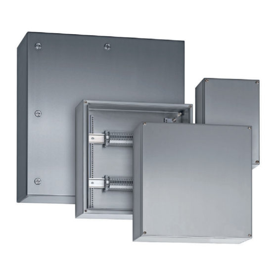
Terminal box
Hide thumbs
Also See for 8150/1 Series:
- Operating instructions manual (76 pages) ,
- Installation operating & maintenance manual (34 pages) ,
- Operating instructions manual (52 pages)

Related Manuals for Stahl 8150/1 Series


Summary of Contents for Stahl 8150/1 Series
- Page 1 Operating Instructions Additional Languages Www.stahl-ex.com Terminal Box Series 8150/1, Series 8150/2...
-
Page 2: Table Of Contents
Contents General Information ....................3 Manufacturer .......................3 About these operating instructions ..............3 Further documents ....................3 Conformity with standards and regulations ............3 Explanation of the symbols .................4 Symbols in these operating instructions .............4 Symbols on the device ..................4 Safety ........................4 Intended Use .......................4 Personnel qualification ..................4 Residual risks ......................5 Transport and storage ..................7... -
Page 3: En En En
• EU Type Examination Certificate For documents in additional languages, see www.stahl-ex.com. Conformity with standards and regulations • Certificates and EU Declaration of Conformity: www.stahl-ex.com. • The device has IECEx approval. See IECEx homepage: http://iecex.iec.ch/ 202161 / 815060300020 Terminal Box 2016-12-13·BA00·III·en·05... -
Page 4: Explanation Of The Symbols
Explanation of the symbols Explanation of the symbols Symbols in these operating instructions Symbol Meaning Tip for making work easier DANGER! Dangerous situation which can result in fatal or severe injuries causing permanent damage if the safety measures are not complied with. -
Page 5: Residual Risks
Use transporting or lifting equipment which is suitable for the size and weight of the device and can reliably carry the weight of the device. Check the packaging and the device for damage. Report any damage to R. STAHL immediately. - Page 6 Devices which have a polyester powder coating must not be installed in areas containing severely charge-producing processes. Do not paint the device. Consult with R. STAHL before mending flaws such as scratches. Comply with the area specification of EN IEC 60079-0 when fitting additional plastic adhesive plates.
-
Page 7: En Transport And Storage
Fit plates (on the outside) only without drilling any additional holes. Only drill additional holes exactly in accordance with the instructions in the "Mounting" chapter. Consult with R. STAHL first if there are any discrepancies or uncertainties. Equip the enclosure only with equipment (e.g. cable entries, stopping plugs, drain and breather valves) that is verifiably approved for use in hazardous areas. -
Page 8: Additional Through Holes In Flange Plates
The methods mainly considered for modification are subsequently machining or equipping the terminal box. In this case, the following possibilities are available: • Additional through holes on the flange plate, either by R. STAHL or by the customer (section 5.1) •... -
Page 9: Additional Through Holes In The Enclosure
(marking in accordance with EN IEC 60079-7 and EN IEC 60079-0, as incomplete equipment "U" inside the enclosure). 5.2.1 Creation of additional drilled holes and through holes by R. STAHL Give the following information to R. STAHL:... - Page 10 Product selection, project engineering and modification R. STAHL • will check whether the components, drilled hole diameters, quantity and position correspond with the approval • will create the drilled holes and through holes • will mount the components • will update the order documentation •...
-
Page 11: External Attached Components (Cable Entries, Stopping Plugs, Breathers)
Product selection, project engineering and modification 3.) Calculate the remaining usable area Subtract the required area for cable entries from the total usable area. Calculation example: Starting conditions: • Dimensions of inner enclosure wall: 297 mm (Side D) x 122 mm (Side C) •... -
Page 12: En En
Product selection, project engineering and modification 5.3.1 Fitting of attached components by R. STAHL Give the following information to R. STAHL: - Type - Data sheet - Quantity, manufacturers and approvals of the components that are to be attached. - Page 13 Product selection, project engineering and modification 5.4.1 Ascertain the number of conductors using the table from the EU Type Examination Certificate Refer to the specifications in the EU Type Examination Certificate for the maximum permitted number of conductors – in relation to the current load and conductor cross-section.
- Page 14 Ensure that operating temperatures – in particular low ones – of the terminal box and the selected electric lines match. 5.4.2 Additional terminals Fitting of additional terminals by R. STAHL Forward the following information to R. STAHL: - Type - Manufacturer - Data sheet...
-
Page 15: Mounting And Installation
Mounting and installation 5.4.3 Fuses Installing, modifying or retrofitting fuses is only permitted to be performed by R. STAHL! When fitting fuses, the ambient temperature values for the following temperature classes apply: Fuse current value Temperature class > 4 A ... ( 5 A >... -
Page 16: En 6.2 Installation
Mounting and installation • Alignment of enclosure depending on mounting type: • For vertical mounting: ≦ 90° any alignment • For horizontal mounting: cover on top • Hanging position/overhanging cover is not permitted! 16523E00 6.1.2 Environmental installation conditions Provide a protective roof or wall if the explosion-protected device is exposed to weather. ... - Page 17 Mounting and installation 6.2.1 Conductor Connection Select suitable conductors that do not exceed the permitted heating temperature within the enclosure. Ensure that conductors have the specified cross-sections. Guide the conductor insulation so that it reaches the terminals. ...
- Page 18 Mounting and installation Distances, creepage distances and clearances When installing components the creepage distances and clearances between the individual components as well as between the components and the enclosure wall must be sufficiently dimensioned. Observe the values from the EN IEC 66079-7 standard (table) when doing so.
-
Page 19: En 7 Commissioning
Perform maintenance on the device according to the applicable national regulations and the safety notes in these operating instructions (chapter 3). Repair Perform repairs to the device only using original spare parts and after consulting with R. STAHL. 202161 / 815060300020 Terminal Box 2016-12-13·BA00·III·en·05... -
Page 20: Returning The Device
Wait for confirmation. R. STAHL's customer service will contact you. You will receive an RMA slip after speaking with customer service. Send the device along with the RMA slip in the packaging to R. STAHL Schaltgeräte GmbH (refer to Section 1.1 for the address). -
Page 21: Annex A
Annex A Annex A 13.1 Technical data Explosion Protection Version 8150/1 8150/2 Global (IECEx) Gas and dust IECEx PTB 09.0048 IECEx PTB 09.0048 Ex db eb ia/ib mb IIA, IIB, IIC T6 Ex ia/ib IIA, IIB, IIC T6 (Ta = -60 ... +40 °C) (Ta = -60 ... - Page 22 300 mm depending on terminal types and explosion protected components used Note please refer to the manufacturer's terminal data, e.g. the tightening torque For further technical data, see www.stahl-ex.com. Terminal Box 202161 / 815060300020 Series 8150/1, Series 8150/2 2016-12-13·BA00·III·en·05...
-
Page 23: Annex B
Annex B Annex B 14.1 Dimensions / fastening dimensions Dimensional Drawings (All dimensions in mm [inches]) - Subject to alterations 25 0 98 0 28 Ø Ø 12648E00 202161 / 815060300020 Terminal Box 2016-12-13·BA00·III·en·05 Series 8150/1, Series 8150/2... - Page 24 Annex B Dimensional Drawings (All dimensions in mm [inches]) - Subject to alterations Width Height Depth Total Fixing dimensions [mm] [mm] [mm] [mm] depth [mm] Type 8150/.-0176-0116- 176.5 116.5 091-..1. [6.95] [4.59] [3.58] [4.17] [5.35] [2.99] [8.35] [5.98] [8.98] [6.61] 8150/.-0176-0176- 176.5 176.5...
Need help?
Do you have a question about the 8150/1 Series and is the answer not in the manual?
Questions and answers