Table of Contents
Advertisement
Available languages
Available languages
Quick Links
Advertisement
Chapters
Table of Contents

Related Manuals for Stahl 8250 Series


Summary of Contents for Stahl 8250 Series
- Page 1 Betriebsanleitung Additional languages r-stahl.com Ex d-Gehäuse aus Aluminium / Druckfeste Kapselung Reihe 8250/0 Leergehäuse, Reihe 8250/1 Klemmenkasten, Reihe 8250/5 Steuerung/Steuerkasten...
-
Page 2: Table Of Contents
Inhaltsverzeichnis Inhaltsverzeichnis Allgemeine Angaben....................3 Hersteller......................3 Zu dieser Betriebsanleitung .................3 Weitere Dokumente .....................3 Konformität zu Normen und Bestimmungen ............3 Erläuterung der Symbole ..................4 Symbole in der Betriebsanleitung ................4 Symbole am Gerät ....................4 Sicherheit ......................5 Bestimmungsgemäße Verwendung..............5 Qualifikation des Personals .................5 Restrisiken ......................6 Transport und Lagerung ..................7 Produktauswahl, Projektierung und Modifikation ..........8 Zusätzliche Bohrungen im Gehäuse..............8... -
Page 3: En Fr
▶ Betriebsanleitung dem Bedien- und Wartungspersonal jederzeit zugänglich machen. ▶ Betriebsanleitung an jeden folgenden Besitzer oder Benutzer des Geräts weitergeben. ▶ Betriebsanleitung bei jeder von R. STAHL erhaltenen Ergänzung aktualisieren. ID-Nr.: 303049 / 825060300230 Publikationsnummer: 2022-08-04·BA00·III·de·00 Die Originalbetriebsanleitung ist die deutsche Ausgabe. -
Page 4: Erläuterung Der Symbole
Erläuterung der Symbole Erläuterung der Symbole Symbole in der Betriebsanleitung Symbol Bedeutung Hinweis zum leichteren Arbeiten Gefahrensituation, die bei Nichtbeachtung der GEFAHR! Sicherheitsmaßnahmen zum Tod oder zu schweren Verletzungen mit bleibenden Schäden führen kann. Gefahrensituation, die bei Nichtbeachtung der WARNUNG! Sicherheitsmaßnahmen zu schweren Verletzungen führen kann. -
Page 5: Se Fi
Normen und Bestimmungen umfasst. Für Tätigkeiten in explosionsgefährdeten Bereichen sind weitere Kenntnisse erforderlich! R. STAHL empfiehlt einen Kenntnisstand, der in folgenden Normen beschrieben wird: • IEC/EN 60079-14 (Projektierung, Auswahl und Errichtung elektrischer Anlagen) • IEC/EN 60079-17 (Prüfung und Instandhaltung elektrischer Anlagen) •... -
Page 6: Restrisiken
▶ Alle Deckelschrauben mit den angegebenen Anzugsdrehmomenten befestigen (siehe Kapitel "Technische Daten"). Dabei darauf achten, dass in jedem Befestigungsloch die dem Einbausatz beigefügte originale Deckelschraube von R. STAHL montiert ist. ▶ Gerät zum Schutz vor Außeneinwirkungen gegebenenfalls mit Schutzgitter absichern. -
Page 7: Gr 4 Transport Und Lagerung
Verletzungen von Personen können die Folge sein. ▶ Schilder (außen) ausschließlich ohne weitere Bohrungen anbringen. ▶ Bohrungen am Gehäuse und Deckel für Anbaukomponenten nur von R. STAHL vornehmen lassen. ▶ Gerät nur in vorgeschriebener Montagelage montieren. Nähere Erläuterungen dazu im Kapitel "Montage"... -
Page 8: Produktauswahl, Projektierung Und Modifikation
Vorschriften durchgeführt werden. Anderenfalls muss sie durch R. STAHL oder eine Prüfstelle (3rd party inspection) (Kapitel 3.3.1) abgenommen werden. Dies kann auf Anfrage gegen ein entsprechendes Angebot durch R. STAHL erfolgen. Werden die Arbeiten durch R. STAHL durchgeführt ist keine zusätzliche Abnahme erforderlich. -
Page 9: Äußere Anbaukomponenten (Leitungseinführungen, Verschlussstopfen, Sk Klimastutzen)
Lockerungsschutz anbringen. 5.2.2 Weitere äußere Anbaukomponenten Weitere Anbaukomponenten dürfen nur durch R. STAHL angebracht werden. Sämtliche in Eigenregie angebrachten Komponenten müssen durch R. STAHL oder eine benannte Prüftstelle (3rd party inspection) einzeln abgenommen werden. 303049 / 825060300230 Ex d-Gehäuse aus Aluminium / Druckfeste Kapselung Reihe 8250/0 Leergehäuse,... -
Page 10: Innere Einbaukomponenten (Leiter, Klemmen)
Produktauswahl, Projektierung und Modifikation Innere Einbaukomponenten (Leiter, Klemmen) Maximale Leiteranzahl ermitteln Durch die Übergangswiderstände an Klemmstellen und durch die im Gehäuse verlegten Leitungen entsteht Wärme. Damit die maximal zulässige Temperatur des Gehäuses nicht überschritten wird, darf die Strombelastung der Stromkreise im Gehäuse nicht zu groß... - Page 11 Produktauswahl, Projektierung und Modifikation Maximalbestückung Klemmen Größe 1: unlackiert berechnet bei Umgebungstemperatur von 40 °C, Stromreduzierungsfaktor 1 Strom Anzahl Leiter bei Erwärmung um 27 K gegenüber der Umgebungstemperatur im Gehäuse [Stück] Querschnitt [mm²] 120 150 185 240 300 max. Anzahl der Klemmen je nach oben genannter Gehäusegröße und Querschnitt bzw. max.
- Page 12 Produktauswahl, Projektierung und Modifikation Größe 2: unlackiert berechnet bei Umgebungstemperatur von 40 °C, Stromreduzierungsfaktor 1 Strom Anzahl Leiter bei Erwärmung um 30 K gegenüber der Umgebungstemperatur im Gehäuse [Stück] Querschnitt [mm²] 120 150 185 240 300 max. Anzahl der Klemmen je nach oben genannter Gehäusegröße und Querschnitt bzw. max.
- Page 13 Produktauswahl, Projektierung und Modifikation Größe 3: unlackiert berechnet bei Umgebungstemperatur von 40 °C, Stromreduzierungsfaktor 1 Strom Anzahl Leiter bei Erwärmung um 30 K gegenüber der Umgebungstemperatur im Gehäuse [Stück] Querschnitt [mm²] 120 150 185 240 300 156 156 156 99 max.
- Page 14 Produktauswahl, Projektierung und Modifikation Größe 5: unlackiert berechnet bei Umgebungstemperatur von 40 °C, Stromreduzierungsfaktor 1 Strom Anzahl Leiter bei Erwärmung um 30 K gegenüber der Umgebungstemperatur im Gehäuse [Stück] Querschnitt [mm²] 120 150 185 240 300 558 558 558 390 312 246 64 max.
- Page 15 5.3.3 Weitere innere Einbaukomponenten Weitere Einbaukomponenten dürfen nur durch R. STAHL angebracht werden. Sämtliche in Eigenregie angebrachten Komponenten müssen durch R. STAHL oder eine benannte Prüftstelle (3rd party inspection) einzeln abgenommen werden. 303049 / 825060300230 Ex d-Gehäuse aus Aluminium / Druckfeste Kapselung Reihe 8250/0 Leergehäuse,...
-
Page 16: Montage Und Installation
Alle Deckelschrauben mit den angegebenen Anzugsdrehmomenten befestigen (siehe Kapitel "Technische Daten"). Dabei darauf achten, dass in jedem Befestigungsloch die dem Einbausatz beigefügte originale Deckelschraube von R. STAHL montiert ist. ▶ Gerät sorgfältig und nur unter Beachtung der Sicherheitshinweise (siehe Kapitel "Sicherheit") montieren. - Page 17 Montage und Installation ▶ Gehäuse mit Hilfe der Befestigungslaschen befestigen (Bemaßung der Befestigungslöcher siehe Maßzeichnung). Dazu Befestigungslaschen mit je zwei Schrauben M8 / M10 über Gewindebohrungen an der Unterseite des Gehäuses anbringen (Anzugsdrehmoment siehe Kapitel "Technische Daten"). Alternative: Gehäuse über Gewindebohrungen direkt an der Rückseite befestigen. ▶...
- Page 18 Montage und Installation ▶ 19118E00 Spaltfläche des Deckels mit einem säurefreiem Fett, das nach EN 60079-14 geeignet ist (z.B. Hevolit), behandeln. 19315E00 ▶ Bei Gehäusegröße 5: Zusätzlichen Positionsstift auf der Seite, die den Scharnieren gegenüberliegt, in das dafür vorgesehene Gewinde schrauben. ▶...
-
Page 19: Installation
Montage und Installation Installation Bei Betrieb unter erschwerten Bedingungen, wie z.B. auf Schiffen oder bei starker Sonneneinstrahlung, sind zusätzliche Maßnahmen zur korrekten Installation je nach Einsatzort zu treffen. Weitere Informationen und Anweisungen hierzu erhalten Sie gerne auf Anfrage von Ihrem zuständigen Vertriebskontakt. GEFAHR! Explosionsgefahr durch starke Erwärmung im Gehäuseinneren! Nichtbeachten führt zu tödlichen oder schweren Verletzungen. - Page 20 Montage und Installation 6.2.2 Schutzleiteranschluss Beim Anschluss eines Schutzleiters prinzipiell beachten: ▶ Stets Schutzleiter anschließen. ▶ Kabelschuhe für äußeren Schutzleiteranschluss verwenden. ▶ Schutzleiter fest und nahe am Gehäuse verlegen (Anzugsdrehmoment siehe Kapitel "Technische Daten"). ▶ Alle blanken, nicht spannungsführenden Metallteile in das Schutzleitersystem einbeziehen.
- Page 21 Montage und Installation 6.2.3 Einbaubedingungen Abstände, Luft- und Kriechstrecken ▶ Beim Einbau von Komponenten Luft- und Kriechstrecken zwischen den einzelnen Komponenten sowie zwischen den Komponenten zu den Gehäusewänden ausreichend bemessen. Hierbei die Werte aus den entsprechenden Normen / Herstellerangaben berücksichtigen. Abstand zwischen Anschlussteilen für eigensichere und nicht-eigensichere Stromkreise ▶...
- Page 22 Montage und Installation 6.2.4 Gehäusedeckel öffnen und schließen GEFAHR! Explosionsgefahr durch beschädigte Spaltflächen! Nichtbeachten führt zu tödlichen oder schweren Verletzungen. ▶ Gehäusedeckel stets vorsichtig anheben, abnehmen und aufsetzen. ▶ Sicherstellen, dass die Deckelschrauben beim Lösen oder Anziehen sowie beim Abnehmen des Deckels die Dichtflächen nicht verkratzen. ▶...
-
Page 23: Instandhaltung, Wartung, Reparatur
▶ Gerät gemäß den geltenden nationalen Bestimmungen und den Sicherheitshinweisen dieser Betriebsanleitung (Kapitel "Sicherheit") warten. Reparatur ▶ Reparaturen am Gerät nur durch R. STAHL durchführen lassen. 303049 / 825060300230 Ex d-Gehäuse aus Aluminium / Druckfeste Kapselung Reihe 8250/0 Leergehäuse, 2022-08-04·BA00·III·de·00... -
Page 24: Rücksendung
▶ Rücksendung bzw. Verpackung der Geräte nur in Absprache mit R. STAHL durchführen! Dazu mit der zuständigen Vertretung von R. STAHL Kontakt aufnehmen. Für die Rücksendung im Reparatur- bzw. Servicefall steht der Kundenservice von R. STAHL zur Verfügung. ▶ Kundenservice persönlich kontaktieren. -
Page 25: Anhang A
Anhang A Anhang A 13.1 Technische Daten Explosionsschutz Ausführung 8250/0 8250/1 8250/5 Global (IECEx) Gas und Staub IECEx BVS 13.0067U IECEx BVS 13.0092X IECEx BVS 13.0092X Ex db IIB Gb Ex db IIB/IIB + H2 Ex db IIB/IIB + H2 Ex db IIB + H2 Gb T6 ... - Page 26 Anhang A Technische Daten Ausführung 8250/0 8250/1 8250/5 Elektrische Daten Bemessungs- – max. 690 V AC/DC betriebsspannung U Bemessungs- – max. 250 A betriebsstrom I Schutzleiter- innen/außen am Gehäuse (Gewindebohrungen), anschluss M8 Gewindeschraube Anzugsdrehmoment: 12 Nm Verlustleistung und 8250/. Größe 1 Temperaturklasse Standard-Lackierung ohne Lackierung...
- Page 27 Anhang A Technische Daten Umgebungsbedingungen Umgebungs- Größe 1 und 2: temperaturbereich -60 ... +70 °C (bei IIB) -60 ... +60 °C (bei IIB + H2) Größe 3 und 5: -20 ... +70 °C (bei IIB) -20 ... +60 °C (bei IIB + H2) Lagertemperatur für -60 ...
- Page 28 Anhang A für 8250/1, 8250/5 Maximalbestückung mit Bohrungen 8250/. Größe 1 metrisch M20x1,5 1/2" M25x1,5 3/4" M32x1,5 1" M40x1,5 1 1/4" M50x1,5 1 1/2" 8250/. Größe 2 metrisch M20x1,5 1/2" M25x1,5 3/4" M32x1,5 1" M40x1,5 1 1/4" M50x1,5 1 1/2" 8250/.
- Page 29 M24x1,5 M25x1,5 M32x1,5 M36x1,5 M75x1,5 M80x2 M95x2 M105x1,5 M112x1,5 M130x2 M132x1,5 M140x2 M172x2 M190x2 M210x2 Weitere technische Daten, siehe r-stahl.com. 303049 / 825060300230 Ex d-Gehäuse aus Aluminium / Druckfeste Kapselung Reihe 8250/0 Leergehäuse, 2022-08-04·BA00·III·de·00 Reihe 8250/1 Klemmenkasten, Reihe 8250/5 Steuerung/Steuerkasten...
-
Page 30: Anhang B
Anhang B Anhang B 14.1 Maßangaben / Befestigungsmaße Maßzeichnungen (alle Maße in mm [Zoll]) – Änderungen vorbehalten 23186E00 8250/. innere Abmessung äußere Abmessung Einbaumaß auf Gehäuse mit Streifen mit Scharnier Abmessung Größe 1 [9,84] [5,91] [3,62] [12,79] [8,86] [4,69] [8,27] [5,91] [8,27] [9,84]... - Page 31 Anhang B Maßzeichnungen (alle Maße in mm [Zoll]) – Änderungen vorbehalten Kollisionsrahmen 19173E00 19172E00 19177E00 19174E00 19176E00 19175E00 Gehäusetyp 8250/. 8250/. 8250/. 8250/. Größe 1 Größe 2 Größe 3 Größe 5 Maß A 215 [8,47] 270 [10,63] 335 [13,19] 495 [19,49] Maß...
- Page 32 Operating instructions Additional languages r-stahl.com Ex d enclosure made of aluminium/ flameproof enclosure 8250/0 series empty enclosure, 8250/1 series terminal box, 8250/5 series control panel/control station...
- Page 33 Contents Contents General Information .....................3 Manufacturer......................3 About these Operating Instructions..............3 Further Documents ....................3 Conformity with Standards and Regulations............3 Explanation of Symbols ..................4 Symbols used in these Operating Instructions.............4 Symbols on the Device ..................4 Safety........................5 Intended Use......................5 Personnel Qualification ..................5 Residual Risks .....................6 Transport and Storage ..................7 Product Selection, Project Engineering and Modification ........8 Additional Drilled Holes in the Enclosure .............8...
-
Page 34: En Fr
Make the operating instructions accessible to operating and maintenance staff at all times. ▶ Pass the operating instructions on to each subsequent owner or user of the device. ▶ Update the operating instructions every time R. STAHL issues an amendment. ID no.: 303049 / 825060300230 Publication code: 2022-05-30·BA00·III·en·00... -
Page 35: Explanation Of Symbols
Explanation of Symbols Explanation of Symbols Symbols used in these Operating Instructions Symbol Meaning Handy hint for making work easier Dangerous situation which can result in fatal or severe injuries DANGER! causing permanent damage if the safety measures are not complied with. -
Page 36: Se Fi
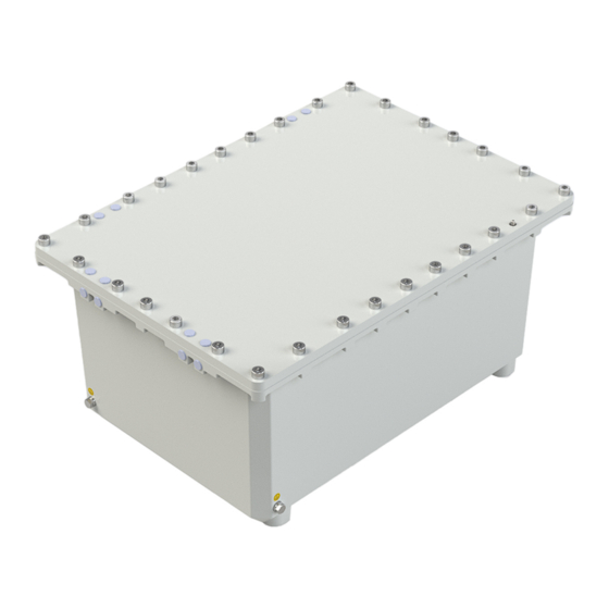
- in accordance with these operating instructions. Intended Use 8250 series components are used to build customer-specific control panels, control stations and terminal boxes in the "Ex d" type of protection. These components are classed as explosion-protected equipment approved for use in Zone 1, 2, 21 and 22 hazardous areas. -
Page 37: Residual Risks
(e.g. scratches, pressure). ▶ Tighten all cover screws to the specified tightening torques (see the "Technical data" chapter). When doing this, ensure that the original R. STAHL cover screw included in the installation kit is mounted in each mounting hole. ▶... -
Page 38: Gr 4 Transport And Storage
(see chapter 3.2). ▶ Only make modifications to the device in accordance with the directions in these operating instructions. Have R. STAHL or a test body (third-party inspection) carry out acceptance testing on any modifications made. ▶... -
Page 39: Product Selection, Project Engineering And Modification
(marking in accordance with EN IEC 60079-1 and EN IEC 60079-0, as incomplete equipment "U" inside the enclosure). Only R. STAHL may drill additional holes. If they are not drilled by R. STAHL, they will need to undergo individual approval by a notified test body (third-party inspection). -
Page 40: External Add-On Components (Cable Entries, Stopping Plugs, Breathers)
Provide protection against loosening. 5.2.2 Additional external Add-On Components Additional add-on components may only be fitted by R. STAHL. Any components attached by the customer must be subjected to individual acceptance testing by R. STAHL or a notified test body (third-party inspection). -
Page 41: Internal Built-In Components (Conductors, Terminals)
Product Selection, Project Engineering and Modification Internal Built-In Components (Conductors, Terminals) Ascertaining the maximum number of conductors Heat develops due to contact resistance at the clamping units and due to the conductors installed in the enclosure. In order to ensure that the maximum permissible temperature of the enclosure is not exceeded, the current load of the electrical circuits in the enclosure must not be too large! 5.3.1 Ascertain the Number of Conductors using the Table from the EU Type Examination... - Page 42 Product Selection, Project Engineering and Modification Maximum number of terminals Size 1: Unpainted Calculated with ambient temperature of 40 °C, current reducing factor 1 Cur- Number of conductors when heated by 27 K compared to the ambient temperature in the enclosure rent [piece] Cross section [mm²]...
- Page 43 Product Selection, Project Engineering and Modification Size 2: Unpainted Calculated with ambient temperature of 40 °C, current reducing factor 1 Cur- Number of conductors when heated by 30 K compared to the ambient temperature in the enclosure rent [piece] Cross section [mm²] 120 150 185 240 300 Maximum number of terminals depending on the aforementioned enclosure size and cross section or maximum permissible conductor cross-section of installed terminals...
- Page 44 Product Selection, Project Engineering and Modification Size 3: Unpainted Calculated with ambient temperature of 40 °C, current reducing factor 1 Cur- Number of conductors when heated by 30 K compared to the ambient temperature in the enclosure rent [piece] Cross section [mm²] 120 150 185 240 300 156 156 156 99 Maximum number of terminals depending on the aforementioned enclosure size and cross section...
- Page 45 Product Selection, Project Engineering and Modification Size 5: Unpainted Calculated with ambient temperature of 40 °C, current reducing factor 1 Cur- Number of conductors when heated by 30 K compared to the ambient temperature in the enclosure rent [piece] Cross section [mm²] 120 150 185 240 300 558 558 558 390 312 246 64 Maximum number of terminals depending on the aforementioned enclosure size and cross section...
- Page 46 If the installation conditions are not observed, retrofitting is not permitted! 5.3.3 Additional internal Built-In Components Only R. STAHL may fit additional built-in components. Any components attached by the customer must be subjected to individual acceptance testing by R. STAHL or a notified test body (third-party inspection). 303049 / 825060300230...
-
Page 47: Mounting And Installation
▶ Tighten all cover screws to the specified tightening torques (see the "Technical data" chapter). When doing this, ensure that the original R. STAHL cover screw included in the installation kit is mounted in each mounting hole. ▶ Mount the device carefully and only in accordance with the safety information (see the "Safety"... - Page 48 Mounting and Installation ▶ Fasten the enclosure using the fastening tabs (see dimensional drawing for dimensions of mounting holes). To do this, use two M8/M10 screws to bolt the fastening tabs into the threaded holes on the underside of the enclosure (see the "Technical data" chapter for tightening torque).
- Page 49 Mounting and Installation ▶ 19118E00 Apply acid-free grease that is suitable according to EN 60079-14 (e.g. Hevolit) to the joint face of the cover. 19315E00 ▶ For enclosure size 5: Screw an additional positioning pin into the thread provided on the side opposite the hinges. ▶...
-
Page 50: Installation
Mounting and Installation Installation Operation under difficult conditions, e.g. on ships or in strong sunlight, requires additional measures to be taken for correct installation, depending on the operating location. Further information and instructions on this can be obtained on request from your designated sales contact. - Page 51 Mounting and Installation 6.2.2 Protective Conductor Connection Always note the following points when connecting a protective conductor: ▶ Always connect a protective conductor. ▶ Use cable lugs for an external protective conductor connection. ▶ Permanently install the protective conductor close to the enclosure (for the tightening torque, see the "Technical data"...
- Page 52 Mounting and Installation 6.2.3 Installation Conditions Distances, creepage distances and clearances ▶ When installing components, the creepage distances and clearances between the individual components, as well as between the components and the enclosure walls, must be sufficiently dimensioned. For this, take into consideration the values in the relevant standards/manufacturer's specifications.
- Page 53 Mounting and Installation 6.2.4 Opening and Closing the Enclosure Cover DANGER! Explosion hazard due to damaged joint faces! Non-compliance results in fatal or severe injuries. ▶ Always carefully lift, take off and attach the enclosure cover. ▶ Make sure that the cover screws do not scratch or scuff the sealing surfaces when they are undone or tightened and when the cover is removed.
-
Page 54: 8 Maintenance, Overhaul, Repair
Perform overhaul of the device according to the applicable national regulations and the safety notes in these operating instructions ("Safety" chapter). Repair ▶ Repair work on the device must be performed only by R. STAHL. 303049 / 825060300230 Ex d enclosure made of aluminium/flameproof enclosure 8250/0 series empty enclosure, 2022-05-30·BA00·III·en·00... -
Page 55: Ee 9 Returning The Device
Returning the Device ▶ Only return or package the devices after consulting R. STAHL! Contact the responsible representative from R. STAHL. R. STAHL's customer service is available to handle returns if repair or service is required. ▶ Contact customer service personally. ▶... -
Page 56: 13.1 Technical Data
Appendix A Appendix A 13.1 Technical Data Explosion protection Version 8250/0 8250/1 8250/5 Global (IECEx) Gas and dust IECEx BVS 13.0067U IECEx BVS 13.0092X IECEx BVS 13.0092X Ex db IIB Gb Ex db IIB/IIB + H2 Ex db IIB/IIB + H2 Ex db IIB + H2 Gb T6 to T4 Gb T6 to T4 Gb... - Page 57 Appendix A Technical data Version 8250/0 8250/1 8250/5 Electrical data Rated operational – Max. 690 V AC/DC voltage U Rated operational – Max. 250 A current I Protective conductor Inside/outside of the enclosure (threaded holes), connection M8 threaded bolt Tightening torque: 12 Nm Power dissipation and 8250/.
- Page 58 Appendix A Technical data Ambient conditions Ambient temperature Size 1 and 2: range -60 to +70 °C (for IIB) -60 to +60 °C (for IIB + H2) Size 3 and 5: -20 to +70 °C (for IIB) -20 to +60 °C (for IIB + H2) Storage temperature -60 to +80 °C for empty enclosure...
- Page 59 Appendix A For 8250/1, 8250/5 Maximum number of drilled holes 8250/. Size 1 Metric M20 x 1.5 1/2" M25 x 1.5 3/4" M32 x 1.5 1" M40 x 1.5 1 1/4" M50 x 1.5 1 1/2" 8250/. Size 2 Metric M20 x 1.5 1/2"...
- Page 60 M132 x 1.5 M140 x 2 M172 x 2 M190 x 2 M210 x 2 For further technical data, see r-stahl.com. 303049 / 825060300230 Ex d enclosure made of aluminium/flameproof enclosure 8250/0 series empty enclosure, 2022-05-30·BA00·III·en·00 8250/1 series terminal box,...
-
Page 61: 14.1 Dimensions/Fastening Dimensions
Appendix B Appendix B 14.1 Dimensions/Fastening Dimensions Dimensional drawings (all dimensions in mm [inch]) – Subject to change 23186E00 8250/. Internal dimensions External dimensions Installation dimensions On enclosure With strip With hinge Dimensions Size 1 [9.84] [5.91] [3.62] [12.79] [8.86] [4.69] [8.27] [5.91]... - Page 62 Appendix B Dimensional drawings (all dimensions in mm [inch]) – Subject to change Collision frame 19173E00 19172E00 19177E00 19174E00 19176E00 19175E00 Enclosure type 8250/. 8250/. 8250/. 8250/. Size 1 Size 2 Size 3 Size 5 Dimension A 215 [8.47] 270 [10.63] 335 [13.19] 495 [19.49] Dimension B...
Need help?
Do you have a question about the 8250 Series and is the answer not in the manual?
Questions and answers