Stahl 8146/1 Series Operating Instructions Manual
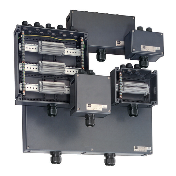
Terminal boxes
Hide thumbs
Also See for 8146/1 Series:
- Operating instructions manual (53 pages) ,
- Operating instructions manual (27 pages) ,
- Operating instructions manual (57 pages)

Related Manuals for Stahl 8146/1 Series


Summary of Contents for Stahl 8146/1 Series
- Page 1 Betriebsanleitung Additional languages r-stahl.com Klemmenkästen Reihe 8146/1, Reihe 8146/2...
-
Page 2: Table Of Contents
Inhaltsverzeichnis Allgemeine Angaben ...................3 Hersteller ......................3 Zu dieser Betriebsanleitung ................3 Weitere Dokumente ....................3 Konformität zu Normen und Bestimmungen ............3 Erläuterung der Symbole ..................4 Symbole in der Betriebsanleitung ...............4 Symbole am Gerät ....................4 Sicherheit ......................5 Bestimmungsgemäße Verwendung ..............5 Qualifikation des Personals ................5 Restrisiken ......................6 Transport und Lagerung ..................8 Produktauswahl, Projektierung und Modifikation ..........8... -
Page 3: De De
Betriebsanleitung während der Lebensdauer des Geräts aufbewahren. Betriebsanleitung dem Bedien- und Wartungspersonal jederzeit zugänglich machen. Betriebsanleitung an jeden folgenden Besitzer oder Benutzer des Geräts weitergeben. Betriebsanleitung bei jeder von R. STAHL erhaltenen Ergänzung aktualisieren. ID-Nr.: 137189 / 8146619300 Publikationsnummer: 2020-02-24·BA00·III·de·09... -
Page 4: Erläuterung Der Symbole
Erläuterung der Symbole Erläuterung der Symbole Symbole in der Betriebsanleitung Symbol Bedeutung Hinweis zum leichteren Arbeiten GEFAHR! Gefahrensituation, die bei Nichtbeachtung der Sicherheitsmaßnahmen zum Tod oder zu schweren Verletzungen mit bleibenden Schäden führen kann. WARNUNG! Gefahrensituation, die bei Nichtbeachtung der Sicherheitsmaßnahmen zu schweren Verletzungen führen kann. -
Page 5: Sicherheit
Normen und Bestimmungen umfasst. Für Tätigkeiten in explosionsgefährdeten Bereichen sind weitere Kenntnisse erforderlich! R. STAHL empfiehlt einen Kenntnisstand, der in folgenden Normen beschrieben wird: • IEC/EN 60079-14 (Projektierung, Auswahl und Errichtung elektrischer Anlagen) • IEC/EN 60079-17 (Prüfung und Instandhaltung elektrischer Anlagen) •... -
Page 6: 3.3 Restrisiken
Hebemittel verwenden, die das Gewicht des Geräts zuverlässig tragen können. Gerät nicht belasten. Verpackung und Gerät auf Beschädigung prüfen. Beschädigungen umgehend an R. STAHL melden. Gerät in Originalverpackung, trocken (keine Betauung), in stabiler Lage und sicher vor Erschütterungen lagern. - Page 7 Personen (siehe Kapitel 3.2) durchführen lassen. Änderungen am Gerät nur entsprechend den Anweisungen in dieser Betriebsanleitung durchführen. Änderungen durch R. STAHL oder eine Prüfstelle (3rd party inspection) abnehmen lassen. Instandhaltung sowie Reparaturen am Gerät nur mit Original-Ersatzteilen und nach Absprache mit R.
-
Page 8: 4 Transport Und Lagerung
Bei der Modifikation wird vor allem eine nachträgliche Bearbeitung bzw. Bestückung der Steuer- und Verteilerkästen in Betracht gezogen. Hierbei stehen folgende Möglichkeiten zur Verfügung: • Zusätzliche Bohrungen an der Flanschplatte, wahlweise durch R. STAHL (Kapitel 5.1.1) oder Kunden (Kapitel 5.1.2.1) • Zusätzliche Bohrungen im Gehäuse, wahlweise durch R. STAHL (Kapitel 5.1.1) oder Kunden (Kapitel 5.1.2.2) -
Page 9: Zusätzliche Bohrungen
Leergehäuse mit entsprechender Kennzeichnung auf dem Gerät gekennzeichnet (Kennzeichnung gem. EN IEC 60079-7 und EN IEC 60079-0, innen im Gehäuse als unvollständiges Betriebsmittel "U"). 5.1.1 Zusätzliche Bohrungen durch R. STAHL anbringen An R. STAHL folgende Informationen übermitteln: - Typ - Datenblatt - Anzahl, Hersteller und Zulassungen der einzubauenden Komponenten. - Page 10 Produktauswahl, Projektierung und Modifikation Dabei folgende Bedingungen beachten: Genügend Abstand zur umlaufenden Dichtung (mind. 3 mm) einplanen (siehe Abbildung, Ausschnitt). Gerät sorgfältig und nur unter Beachtung der Sicherheitshinweise (siehe Kapitel "Sicherheit") verändern. Nutzbare Fläche berechnen. Zusätzliche Bohrungen durch Lasern oder Stanzen (Bohren, Lochschneiden) einbringen. ...
- Page 11 Produktauswahl, Projektierung und Modifikation 1.) Gesamte nutzbare Fläche berechnen Die gesamte, nutzbare Fläche für den Einbau errechnet sich wie folgt: Gehäuse: (Gehäuseinnenwand-Länge ‒ 2 x 10 mm ) x (Gehäuseinnenwand-Höhe ‒ 2 x 10 mm *2 x 10 mm = umlaufender Rand an der Gehäuseinnenwand ...
- Page 12 Produktauswahl, Projektierung und Modifikation 2.) Benötigte Fläche für Leitungseinführungen berechnen Anzahl der gewünschten Leitungseinführungen mit den Platzbedarf-Werten des passenden Typs aus folgender Tabelle multiplizieren. Gewindedurchmesser der Leitungseinführung ≤ 12 mm ≤ 16 mm ≤ 20 mm ≤ 25 mm ≤ 32 mm ≤ 40 mm ≤ 50 mm ≤ 63 mm Platz- 315 mm 495 mm...
- Page 13 Produktauswahl, Projektierung und Modifikation Gerät sorgfältig und nur unter Beachtung der Sicherheitshinweise (siehe Kapitel "Sicherheit") verändern. Nutzbare Fläche für Einbaukomponenten berechnen. Zusätzliche Bohrungen durch Lasern oder Stanzen (Bohren, Lochschneiden) einbringen. Dabei Abstände zum Rand des Gehäuses einhalten (siehe Abbildungen in diesem Kapitel, Abschnitt "Gehäuse"...
- Page 14 Gehäuse werksseitig mit einem Staub- und Transportschutz versehen (Klebeband mit Warnhinweis oder Abdeckkappen aus Kunststoff). 5.2.1 Anbaukomponenten durch R. STAHL anbringen An R. STAHL folgende Informationen übermitteln: - Typ - Datenblatt - Anzahl, Hersteller und Zulassungen der anzubauenden Komponenten.
-
Page 15: Innere Einbaukomponenten
Produktauswahl, Projektierung und Modifikation Innere Einbaukomponenten Maximale Leiteranzahl ermitteln Durch die Übergangswiderstände an Klemmstellen und durch die im Gehäuse verlegten Leitungen entsteht Wärme. Damit die maximal zulässige Temperatur des Gehäuses nicht überschritten wird, darf die Strombelastung der Stromkreise im Gehäuse nicht zu groß... - Page 16 Darauf achten, dass – insbesondere niedrige – Einsatztemperaturen des Klemmenkastens und der gewählten Leitungen übereinstimmen. 5.3.2 Zusätzliche Klemmen Zusätzliche Klemmen durch R. STAHL anbringen An R. STAHL folgende Informationen weitergeben: - Typ - Hersteller - Datenblatt - Anzahl - Gehäusegröße...
- Page 17 Im Schutzleiter müssen alle leitenden Teile aufgenommen werden, z.B. auch große, umfassbare Teile oder Teile größer als 50 x 50 mm (gemäß IEC/EN 61439). 5.3.3 Sicherungen Einbau, Änderung oder Nachrüsten von Sicherungen ist nur durch R. STAHL gestattet! Für den Einbau von Sicherungen gelten folgende Temperaturklassen der zugehörigen Umgebungstemperaturwerte: Sicherungsstromwert Temperaturklasse ≤...
-
Page 18: Montage Und Installation
Montage und Installation Montage und Installation Montage / Demontage Gerät sorgfältig und nur unter Beachtung der Sicherheitshinweise (siehe Kapitel "Sicherheit") montieren. Folgende Einbaubedingungen und Montageanweisungen genau durchlesen und exakt befolgen. 6.1.1 Gebrauchslage GEFAHR! Explosion durch falsche Montagelage! Nichtbeachten führt zu tödlichen oder schweren Verletzungen. ... -
Page 19: Installation
Montage und Installation Installation Gerät sorgfältig und nur unter Beachtung der Sicherheitshinweise (Kapitel "Sicherheit") installieren. Die im Folgenden genannten Installationsschritte mit großer Genauigkeit durchführen. Bei Betrieb unter erschwerten Bedingungen, wie z.B. auf Schiffen oder bei starker Sonneneinstrahlung, sind zusätzliche Maßnahmen zur korrekten Installation je nach Einsatzort zu treffen. - Page 20 Montage und Installation Kabelübergangskästen 05473E00 Der Leiteranschluss ist nur mit Kabelschuh zulässig. Ist das Maß "I" größer als 65 mm, muss der Kabelschuh mit einem Schrumpfschlauch (ähnlich DIN 47632) isoliert werden. 21716E00 Legende = Sechskantschraube M12 = Winkel 8146 für Sammelschiene = Sechskantmutter M12 = Schiene 8146 (L = 36 mm) (Anzugsdrehmoment: 14 Nm)
- Page 21 Montage und Installation 6.2.2 Einbaubedingungen Einbaubedingungen Luft- und Kriechstrecken Mindestabstand zum Gehäuse nach Norm EN IEC 60079-7 (Tabelle) Luftstrecke Faktor nach Norm EN IEC 60079-7 abhängig vom Leiterquerschnitt X I * 18591E00 X * I = Mindestabstand 18590E00 18592E00 50 mm Abstand zwischen Ex e und Ex i Reihenklemmen 8 mm Abstand zwischen Ex e und Ex i Kabelleitung...
- Page 22 Montage und Installation Abstand zwischen Anschlussteilen für eigensichere und nicht-eigensichere Stromkreise Trennwände, die zur Trennung der Anschlussklemmen verwendet werden, mindestens 1,5 mm von der Gehäusewände montieren oder aber einen Mindestabstand von 50 mm zwischen den blanken leitfähigen Teilen der Anschlussklemmen sicherstellen (gemessen um die Trennwand nach allen Richtungen) ...
-
Page 23: Instandhaltung, Wartung, Reparatur
• Sicherstellen der bestimmungsgemäßen Verwendung. Wartung Gerät gemäß den geltenden nationalen Bestimmungen und den Sicherheitshinweisen dieser Betriebsanleitung (Kapitel "Sicherheit") warten. Reparatur Reparaturen am Gerät nur mit Original-Ersatzteilen und nach Absprache mit R. STAHL durchführen. 137189 / 8146619300 Klemmenkästen 2020-02-24·BA00·III·de·09... -
Page 24: Rücksendung
Rücksendung Rücksendung Rücksendung bzw. Verpackung der Geräte nur in Absprache mit R. STAHL durchführen! Dazu mit der zuständigen Vertretung von R. STAHL Kontakt aufnehmen. Für die Rücksendung im Reparatur- bzw. Servicefall steht der Kundenservice von R. STAHL zur Verfügung. -
Page 25: Anhang A
Anhang A Anhang A 13.1 Technische Daten Explosionsschutz Global (IECEx) Gas und Staub IECEx PTB 06.0046 Ex db eb ia ib mb IIA, IIB, IIC T6…T4 Gb (8146/1) Ex ia ib IIA, IIB, IIC T6…T4 Gb (8146/2) Ex tb IIIC T80 °C…T130 °C Db Europa (ATEX) Gas und Staub PTB 01 ATEX 1016... - Page 26 Anhang A Technische Daten Anschluss- querschnitt Reihenklemmen Einsetzbarer Bemessungsquerschnitt max. 300 mm Die max. Klemmenbestückung für die jeweilige Gehäusegröße ist der EU-Baumusterprüfbescheinigung zu entnehmen Montage / Installation Anschluss Auftragsbedingt, direkt auf die Einbaugeräte oder auf die Reihenklemmen. Bemessungsbetriebsspannung, Bemessungsbetriebsstrom, Bemessungsquerschnitt sind abhängig vom verwendeten Klemmentyp und den Ex-Bauteilen.
- Page 27 Leitungs- Standard: Aus Polyamid, Standard: Aus Polyamid, Standard: Aus Polyamid, einführungen Reihe 8161 Reihe 8161 Reihe 8161 Sonder: Aus Metall Sonder: Aus Metall Sonder: Aus Metall Weitere technische Daten, siehe r-stahl.com. 137189 / 8146619300 Klemmenkästen 2020-02-24·BA00·III·de·09 Reihe 8146/1, Reihe 8146/2...
-
Page 28: Anhang B
Anhang B Anhang B 14.1 Maßangaben / Befestigungsmaße Maßzeichnungen (alle Maße in mm [Zoll]) – Änderungen vorbehalten 04180E00 03179E00 04303E00 8146/.03. 8146/.04. 8146/.05. 04304E00 04305E00 8146/.06. 8146/.07. 04306E00 04307E00 8146/.S7. 8146/.08. Klemmenkästen 137189 / 8146619300 Reihe 8146/1, Reihe 8146/2 2020-02-24·BA00·III·de·09... - Page 29 Anhang B Maßzeichnungen (alle Maße in mm [Zoll]) – Änderungen vorbehalten 04308E00 8146/.09. Gehäusehöhe h Gehäuse 8146/...1 8146/...2 8146/...3 8146/...5 8146/...6 Flansch- Maß 91 mm 131 mm 150 mm 190 mm 230 mm dicke [mm] [mm] 8146/.03. X – – –...
- Page 31 Operating instructions Additional languages r-stahl.com Terminal Boxes Series 8146/1, Series 8146/2...
- Page 32 Contents General Information ....................3 Manufacturer .......................3 About these Operating Instructions ..............3 Further Documents .....................3 Conformity with Standards and Regulations ............3 Explanation of the Symbols ................4 Symbols in these Operating Instructions ............4 Symbols on the Device ..................4 Safety ........................5 Intended Use .......................5 Personnel Qualification ..................5 Residual Risks ....................6 Transport and Storage ..................8...
-
Page 33: En En
• EU Type Examination Certificate For documents in additional languages, see r-stahl.com. Conformity with Standards and Regulations • Certificates and EU Declaration of Conformity: r-stahl.com. • The device has IECEx approval. See IECEx homepage: http://iecex.iec.ch/ to view the certificate. 137189 / 8146619300 Terminal Boxes 2020-02-24·BA00·III·en·09... -
Page 34: Explanation Of The Symbols
Explanation of the Symbols Explanation of the Symbols Symbols in these Operating Instructions Symbol Meaning Tip for making work easier DANGER! Dangerous situation which can result in fatal or severe injuries causing permanent damage if the safety measures are not complied with. -
Page 35: Safety
Specialists who perform these tasks must have a level of knowledge that meets applicable national standards and regulations. Additional knowledge is required for tasks in hazardous areas! R. STAHL recommends having a level of knowledge equal to that described in the following standards: •... -
Page 36: 3.3 Residual Risks
Do not place any load on the device. Check the packaging and the device for damage. Report any damage to R. STAHL immediately. Store the device in its original packaging in a dry place (with no condensation), and make sure that it is stable and protected against the effects of vibrations and knocks. - Page 37 Only drill holes for cable entries exactly according to the instructions in the "Product selection, project engineering and modification" and "Mounting" sections of these operating instructions. Consult with R: STAHL first if there are any discrepancies or uncertainties. Install the device only in the prescribed mounting position. More detailed explanations of this can be found in the "Mounting"...
-
Page 38: 4 Transport And Storage
The primary methods considered for modification are remachining or retrofitting equipment to the control and distribution boxes. The following options are available for this: • Additional drilled holes on the flange plate, either by R. STAHL (Section 5.1.1) or by the customer (Section 5.1.2.1) •... -
Page 39: Additional Drilled Holes
(marking in accordance with EN IEC 60079-7 and EN IEC 60079-0 as incomplete equipment "U" inside the enclosure). 5.1.1 Additional Drilled Holes by R. STAHL Give the following information to R. STAHL: - Type - Data sheet - Quantity, manufacturers and approvals of the components that are to be installed. -
Page 40: Cable Entries, Stopping Plugs, Breathers)
Product Selection, Project Engineering and Modification Observe the following conditions when doing so: Leave enough distance to the circumferential seal (min. 3 mm) (see detail in figure). Modify the device carefully and only in accordance with the safety information (see "Safety"... - Page 41 Product Selection, Project Engineering and Modification 1.) Calculate the total usable area The total usable area for installation is calculated as follows: Enclosure: (Length of the inner enclosure wall - 2 x 10 mm (Height of the inner enclosure wall - 2 x 10 mm *2 x 10 mm = circumferential rim of the inner enclosure wall ...
- Page 42 Product Selection, Project Engineering and Modification 2.) Calculate the required area for cable entries Multiply the quantity of desired cable entries by the space requirement values of the appropriate type from the following table. Cable entry thread diameter ≤ 12 mm ≤ 16 mm ≤ 20 mm ≤ 25 mm ≤ 32 mm ≤ 40 mm ≤ 50 mm ≤ 63 mm Required 315 mm 495 mm...
- Page 43 Product Selection, Project Engineering and Modification Modify the device carefully and only in accordance with the safety information (see "Safety" section). Calculate the usable area for built-in components. Create additional drilled holes through lasing or punching (drilling, hole cutting). When doing so, maintain the stipulated distances to the rim of the enclosure (see figures in this chapter, "Enclosure"...
- Page 44 If customers intend to fit the components in the holes themselves, dust and transport protection is provided for the openings in the enclosure (adhesive tape with a warning note or plastic caps) at the factory. 5.2.1 Fitting of Attached Components by R. STAHL Give the following information to R. STAHL: - Type - Data sheet - Quantity, manufacturers and approvals of the components that are to be attached.
-
Page 45: Internal Built-In Components
Product Selection, Project Engineering and Modification Internal Built-In Components Ascertaining the maximum number of conductors Heat develops due to contact resistance at the terminal points and due to the electric lines installed in the enclosure. In order to ensure that the maximum permissible temperature of the enclosure is not exceeded, care should be taken that the current load of the electric circuits in the enclosure does not exceed certain values. - Page 46 Ensure that operating temperatures of the terminal box and the selected electric lines (in particular low temperatures) match. 5.3.2 Additional Terminals Fitting of additional terminals by R. STAHL Forward the following information to R. STAHL: - Type - Manufacturer - Data sheet...
- Page 47 50 x 50 mm (according to IEC/EN 61439). 5.3.3 Fuses Installing, modifying or retrofitting fuses is only permitted to be performed by R. STAHL! When fitting fuses, the ambient temperature values for the following temperature classes apply:...
-
Page 48: Mounting And Installation
Mounting and Installation Mounting and Installation Mounting / Dismounting Mount the device carefully and only in accordance with the safety notes (see Chapter "Safety"). Read through the following installation conditions and assembly instructions carefully and follow them precisely. 6.1.1 Operating Position DANGER! Explosion if device mounted in incorrect mounting position! Non-compliance may result in serious or even fatal injuries. -
Page 49: Installation
Mounting and Installation Installation Install the device carefully and only in accordance with the safety notes ("Safety" chapter). The installation steps stated below must be carried out very precisely. Operation under difficult conditions, such as on ships or in strong sunlight, requires additional measures to be taken to ensure that the device is installed correctly, depending on the operating location. - Page 50 Mounting and Installation Cable end boxes 05473E00 Conductors must be connected only using cable lug. If dimension "I" is greater than 65 mm, the cable lug must be insulated using a heat-shrink tubing (similar to DIN 47632). 21716E00 Legend = M12 hexagon screw = 8146 bracket for busbar = M12 hexagon nut = 8146 bar (L = 36 mm)
- Page 51 Mounting and Installation 6.2.2 Installation Conditions Installation conditions for creepage distances and clearances Minimum distance from the enclosure in accordance with EN IEC 60079-7 standard (table) Clearance Factor in accordance with X I * EN IEC 60079-7 depending on 18591E00 conductor cross section X * I = Minimum distance 18590E00...
- Page 52 Mounting and Installation Distance between the connecting units for intrinsically safe and non-intrinsically safe electric circuits Mount partitions used to separate connection terminals at least 1.5 mm from the enclosure walls, or alternatively ensure a minimum distance of 50 mm between the uncoated conducting parts of the connection terminals (when measured in any direction around the partition) ...
-
Page 53: Maintenance, Overhaul, Repair
Perform maintenance on the device according to the applicable national regulations and the safety notes in these operating instructions ("Safety" chapter). Repair Perform repairs to the device only with original spare parts and after consultation with R. STAHL. 137189 / 8146619300 Terminal Boxes 2020-02-24·BA00·III·en·09... -
Page 54: Returning The Device
Only return or package the devices after consulting R. STAHL! Contact the responsible representative from R. STAHL. R. STAHL's customer service is available to handle returns if repair or service is required. Contact customer service personally. Go to the r-stahl.com website. -
Page 55: Annex A
Annex A Annex A 13.1 Technical Data Explosion Protection Global (IECEx) Gas and dust IECEx PTB 06.0046 Ex db eb ia ib mb IIA, IIB, IIC T6…T4 Gb (8146/1) Ex ia ib IIA, IIB, IIC T6…T4 Gb (8146/2) Ex tb IIIC T80 °C…T130 °C Db Europe (ATEX) Gas and dust PTB 01 ATEX 1016... - Page 56 Annex A Technical Data Connection cross-section Terminals Rated cross section that can be used, max. 300 mm The maximum number of terminals for the respective enclosure size is indicated in the EU Type Examination Certificate. Mounting / Installation Connection According to the order directly to the fitted components or to the terminal blocks.
- Page 57 Standard: In polyamide, Standard: In polyamide, Standard: In polyamide, Series 8161 Series 8161 Series 8161 Special: In metal Special: In metal Special: In metal For further technical data, see r-stahl.com. 137189 / 8146619300 Terminal Boxes 2020-02-24·BA00·III·en·09 Series 8146/1, Series 8146/2...
-
Page 58: Annex B
Annex B Annex B 14.1 Dimensions / Fastening Dimensions Dimensional drawings (all dimensions in mm [inches]) – Subject to modifications 04180E00 03179E00 04303E00 8146/.03. 8146/.04. 8146/.05. 04304E00 04305E00 8146/.06. 8146/.07. 04306E00 04307E00 8146/.S7. 8146/.08. Terminal Boxes 137189 / 8146619300 Series 8146/1, Series 8146/2 2020-02-24·BA00·III·en·09... - Page 59 Annex B Dimensional drawings (all dimensions in mm [inches]) – Subject to modifications 04308E00 8146/.09. Enclosure height h Enclosure 8146/...1 8146/...2 8146/...3 8146/...5 8146/...6 Flange 91 mm 131 mm 150 mm 190 mm 230 mm thickness men- [mm] sion 8146/.03. X –...
Need help?
Do you have a question about the 8146/1 Series and is the answer not in the manual?
Questions and answers