Table of Contents
Advertisement
Advertisement
Table of Contents

Related Manuals for THORLABS PM400


Summary of Contents for THORLABS PM400
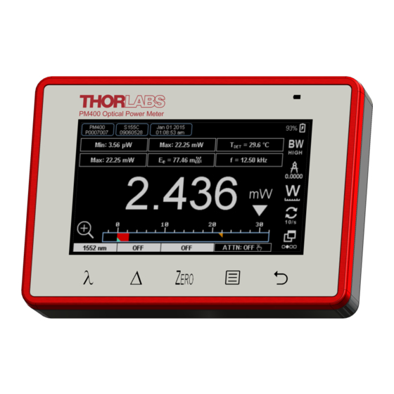
- Page 1 Optical Power and Energy Meter PM400 Operating Manual 2017...
- Page 2 Version: Date: 14-Jul-2017 Copyright © 2017 Thorlabs GmbH...
-
Page 3: Table Of Contents
5.4 Simple LabVIEW Example using SCPI commands 5.5 SCPI Commands 5.5.1 An Introduction to the SCPI language 5.5.2 IEEE488.2 Common Commands 5.5.2.1 Command Summary 5.5.2.2 Command Reference 5.5.2.3 PM400 specific SCPI Command Reference 6 Maintenance and Service 6.1 Version Information... - Page 4 7 Appendix 7.1 Sensor Connector Pinning 7.2 Technical Data 7.3 Certifications and Compliances 7.4 Symbols and Abbreviations 7.5 Warranty 7.6 Copyright and Exclusion of Reliability 7.7 Thorlabs 'End of Life' Policy 7.8 Thorlabs Worldwide Contacts...
-
Page 5: Foreword
Paragraphs preceeded by this symbol explain hazards that could damage the instrument and the connected equipment or may cause loss of data. Note This manual also contains "NOTES" and "HINTS" written in this form. Please read these advices carefully! © 2017 Thorlabs GmbH... -
Page 6: General Information
PM400 1 General Information The PM400 Handheld Optical Power and Energy Meter is designed to measure the optical power of laser light or other monochromatic or near monochromatic light sources and the ener- gy of pulsed light sources. The space-saving, battery powered design is compatible with all Thorlabs “C-Series” Photodi- ode, Thermal, Pyroelectric sensors, and custom Photodiode, Thermal and Pyroelectric detec- tors. -
Page 7: Ordering Codes And Accessories
Please visit our homepage http://www.thorlabs.com for various accessories like fiber adapters, posts and post holders, data sheets and further information. 1.3 Requirements These are the requirements to the PC intended to be used for remote operation of the PM400. Hardware Requirements CPU:... -
Page 8: Getting Started
Inspect the shipping container for damage. If the shipping container seems to be damaged, keep it until you have inspected the contents and you have inspected the PM400 mechanically and electrically. Verify that you have received the following items within the package: 1. - Page 9 (Charging via PC @ 0.5 A, charging via adapter @ 1 A) Analog Output Signal 2P audio jack Ø 3.5 mm 9 Pin DSUB for connection of Thorlabs C-Series Power and Energy sensors; Custom detectors Connector for External Temperature Sensor TSP-TH (NTC) 3P audio jack Ø...
-
Page 10: Installing Software
PM400 2.3 Installing Software For the PM400 a software package is available on the Thorlabs GmbH website: https://www.thorlabs.de/software_pages/viewsoftwarepage.cfm?code=PM100x This software package contains: · NI VISA 5.4.1 Runtime · NI LabView Runtime 2015 · Thorlabs PM100 Utility Version 5.8 · Thorlabs Instrument Communicator 2 Version 1.5.0 ·... - Page 11 2 Getting Started NI VISA 5.4.1 Runtime Click "Install", then "Next" to continue. Click "Next" to continue. We recommend to uncheck the box that is marked red. Then click "Next" to continue. © 2017 Thorlabs GmbH...
- Page 12 Select "I accept..." if you do so, then click "Next" to continue. Click "Next" to continue. You might be prompted to restart the computer. In order to ensure proper installation of subse- quent components, it is strongly recommended to restart your computer now. © 2017 Thorlabs GmbH...
- Page 13 NI LabView Runtime 2015 After rebooting the computer, the installer continues automatically. Note If the installation process does not resume automatically, please execute the setup.exe anew. Click "Install", then "Next" to continue. Click "Next" to continue. © 2017 Thorlabs GmbH...
- Page 14 PM400 We recommend to uncheck the box that is marked red. Then click "Next" to continue. Select "I accept..." if you do so, then click "Next" to continue. Click "Next" to continue. © 2017 Thorlabs GmbH...
- Page 15 Installing Thorlabs Software After rebooting the computer, the installer continues automatically. Note If the installation process does not resume automatically, please execute the setup.exe anew. Click "Next" to continue. © 2017 Thorlabs GmbH...
- Page 16 PM400 Select "I accept..." if you do so, then click "Next" to continue. Click "Next", then "Install" to continue. © 2017 Thorlabs GmbH...
- Page 17 Read the information, then click "Next". In the last window click "Finish". On the desktop three new icons appear that allow to execute the installed software. Switch on your PM400, and connect it to a free USB port using the USB cable that was atta- ched. The required driver software is being installed.
- Page 18 PM400 Start the application from the Optical Power Meter Utility icon. The GUI opens and you will be prompted for device selection: © 2017 Thorlabs GmbH...
-
Page 19: Operating Instruction
· Switch on the PM400. · The PM400 starts in the last view that was used before shutdown. 3.1 Measurement Screens Needle Screen Analog needle simulation with digital measurement value. The needle has a factor 10 zooming function. - Page 20 The graph display allows to capture measurements over time and to analyze the results. Start / Stop Capturing Show all results/ Roll latest Open folder with captured files Analyze capture (Switch to Viewer Mode) Next Screen Graph Display in Capturing Mode © 2017 Thorlabs GmbH...
- Page 21 Graph Display in Viewer Mode Statistics Display In the Statistics Display a sequential measurement can be started. The display then shows typi- cal statistic values over the expired time / samples. Start / Stop Sampling Next Screen Statistics Display © 2017 Thorlabs GmbH...
-
Page 22: Measurement Configuration
PM400 3.2 Measurement Configuration Ranging The PM400 can be operated in AUTO and MANUAL ranging mode. Tap on the measurement unit ("mW") to toggle between AUTO and MANUAL ranging. When AUTO is enabled, the arrows are are shown in outlines. -
Page 23: Spectral Correction
Now you can create an entry in either nanometers, micrometers or wavenumber or to load a light spectrum curve in .csv format. Confirm and chose your entry The actual wavelength setting value displays in the field above the button in Needle and Nu- merical measurement screens. © 2017 Thorlabs GmbH... -
Page 24: Delta Mode
The scale-based indicators go to a middle setting. 3.5 Zeroing Press the button to enter the Zeroing menu. Follow the displayed instructions. After successful Zeroing, the Zero value is displayed in the field above the button in Need- le and Numerical measurement screens. © 2017 Thorlabs GmbH... -
Page 25: Attenuation Correction
Then tap the edited entry to activate it. With active correction, the button displays in a different color and shows the set value: To disable the correction press and hold the ATTN button for 2 seconds, or chose an entry with “OFF”. © 2017 Thorlabs GmbH... -
Page 26: Data Handling
PM400 3.7 Data Handling The PM400 has an internal 4 GB flash memory that holds captured measurement data, specific correction, and language files. This internal memory is allocated by default to the system. For accessing or modifying these data externally, and adding or removing files, the memory can be mounted to a USB link to a PC. -
Page 27: Subpanels
Ratio (Max/Min) (not available) Sensor Temperature Sensor Temperature Frequency Frequency Frequency Ext. NTC Temperature Ext. NTC Temperature Ext. NTC Temperature Irradiance E Irradiance E Fluence H ) - Available only if a sensor-internal temperature sensor is detected. © 2017 Thorlabs GmbH... -
Page 28: Main Menu
PM400 3.9 Main Menu Pressing the button, opens the PM400 Main Menu. Submenu Display · Display brightness · Skin (dark or light) · Language (English, German, Chinese or French) · Enable / disable button sound · Lock / unlock GUI control; in Remote operation: performs GTL (Go To Local) command Submenu Power Options ·... - Page 29 Select type of custom sensor, if used Submenu System Info Submenu Sensor Info Submenu File Manager · Manage files in the Flash memory Button Memory Owner · Assign the Flash memory access between PM400 or a connected via USB PC © 2017 Thorlabs GmbH...
-
Page 30: Charging The Battery
These chargers have a so called "Dedicated Charging Port". In this case, the PM400 enters the high current charging mode, with a maximum current of 1 A. -
Page 31: Computer Interface
4 Computer Interface 4 Computer Interface The PM400 optical power meter contains a USB 2.0 interface for remote control of the unit by an external PC. Connect the unit via the Mini-USB connector in the top panel to a free USB port of your PC. - Page 32 PM400 Front Panel Description of the Front Panel Elements Header This indicator shows the device setup: - console type (PM400) - serial number of the console - sensor type - sensor serial number Main Display The display has a configurable display resolution. Independent from the measurement range the display always has the full num- ber of the selected digits.
- Page 33 - clear power / energy statistics - clear log screen Shortcut: [Shift + F7] Quit button - stops the PM400 application - to restart press the white arrow in the tool bar Shortcut: [Shift + F8] © 2017 Thorlabs GmbH...
-
Page 34: Using The Instrument Drivers
PC which you are performing the install. Prior to connecting the PM400 with a PC, please check if NI-VISA is installed on the PC, other- wise install NI-VISA that is available for free from the National Instruments website www.ni.com or from the data carrier that came with the instrument. -
Page 35: Write Your Own Application
Windows XP (32 bit) and Windows 7 (32 and 64 bit) Note PM400 software and drivers contains 32 bit and 64 bit applications. In 32 bit systems, only the 32 bit components are installed to C:\Program Files\... -
Page 36: Windows Xp 32Bit
C:\Program Files\Microsoft.NET\Primary Interop Assemblies\..Thorlabs.PM100D.dll Examples ANSI-C C:\Program Files\IVI Foundation\VISA\WinNT\PM100D\Samples\C\sample.c Thorlabs PM100x/PM160/PM200 Instrument Driver Sample Application with console interface. Read the comment text in the sample.c file for more information. C# Visual Studio 2010 C:\Program Files\IVI Foundation\VISA\WinNT\PM100D\Samples\..DotNet\DotNetSample.csproj Very basic C# sample project. The application opens a session to a device takes one measure- ment and closes the device again. -
Page 37: Windows Vista / 7 / 8 - 32Bit
C:\Program Files\Microsoft.NET\Primary Interop Assemblies\..Thorlabs.PM100D.dll Examples: ANSI-C C:\Program Files\IVI Foundation\VISA\WinNT\PM100D\Samples\C\sample.c Thorlabs PM100x/PM160/PM200 Driver Sample Application with console interface. Read the comment text in the sample.c file for more information. C# Visual Studio 2010 C:\Program Files\IVI Foundation\VISA\WinNT\PM100D\Samples\..DotNet\DotNetSample.csproj Very basic C# sample project. The application opens a session to a device takes one measure- ment and closes the device again. -
Page 38: Windows Vista / 7 / 8 - 64Bit
C:\Program Files (x86)\IVI Foundation\VISA\WinNT\include\PM100D.h Header File 64bit C:\Program Files\IVI Foundation\VISA\Win64\include\PM100D.h Static Library 32bit C:\Program Files (x86)\IVI Foundation\VISA\WinNT\lib\msc\PM100D_32.lib Static Library 64bit C:\Program Files\IVI Foundation\VISA\Win64\Lib_x64\msc\PM100D_64.lib Function Panel 32bit C:\Program Files (x86)\IVI Foundation\VISA\WinNT\PM100D\PM100D.fp Function Panel 64bit C:\Program Files\IVI Foundation\VISA\Win64\PM100D\PM100D.fp © 2017 Thorlabs GmbH... - Page 39 C:\Program Files\IVI Foundation\VISA\VisaCom64\..Primary Interop Assemblies\Thorlabs.PM100D.dll Examples: ANSI-C C:\Program Files\IVI Foundation\VISA\Win64\PM100D\Samples\C\sample.c Thorlabs PM100x/PM160/PM200 Driver Sample Application with console interface. Read the comment text in the sample.c file for more information. C# Visual Studio 2010 C:\Program Files\IVI Foundation\VISA\Win64\PM100D\Samples\DotNet\..DotNetSample_64.csproj Very basic C# sample project. The application opens a session to a device takes one measure- ment and closes the device again.
-
Page 40: Simple Labview Example Using Scpi Commands
The PM400 Instrument driver is not required for this LabVIEW example. PM100D Simple Example.vi This VI shows how to communicate with a PM400 optical power/energy meter with SCPI commands. The following steps are demonstrated within this application: - Initializing the instrument... - Page 41 5 Write Your Own Application Block Diagram © 2017 Thorlabs GmbH...
- Page 42 Sensor flag bitmap: Is power sensor Is energy sensor 16 Response settable 32 Wavelength settable 64 Tau settable 256 Has temperature sensor Sensor Name Name of connected power/energy sensor Sensor SN Serial number of connected power/energy sensor © 2017 Thorlabs GmbH...
- Page 43 - Clear operation register with STAT:OPER? - INITiate measurement PM100D_SYST-ERR.vi This VI lists all errors coming from the instrument with the command SYST:ERR? 'no error' is suppressed PM100D_Close.vi Closes the VISA session Sets the connected instrument in local mode (default option) © 2017 Thorlabs GmbH...
-
Page 44: Scpi Commands
PM400 5.5 SCPI Commands This section describes in detail the SCPI command set with respect to PM400 power meter console. However, these commands are compatible with PM100A, PM100D and PM100USB consoles as well as with the PM160 Hand-held Power Meter, except some console and sensor related functions. - Page 45 If you send two query commands without reading the response from the first, and then attempt to read the second response, you may receive some data from the first response followed by the complete second response. To avoid this, do not send a query command without reading © 2017 Thorlabs GmbH...
- Page 46 You can include the quote delimiter as part of the string by typing it twice without any charac- ters in between. The following command uses a string parameter: DIAG:CALString <quoted string> © 2017 Thorlabs GmbH...
-
Page 47: Ieee488.2 Common Commands
Reads the Service Request Enable Register *STB? Status byte query Reads the Status Byte Register Performs the unit’s self-test and returns the re- Self-test query *TST? sult. Wait until all previous commands are execu- *WAI Wait-to-continue command © 2017 Thorlabs GmbH... -
Page 48: Command Reference
5.5.2.2 Command Reference *IDN? – identification query - read identification code The identification code includes the manufacturer, model code, serial number, and firmware re- vision levels and is sent in the following format: THORLABS,MMM,SSS,X.X.X Where: MMM is the model code SSS is the serial number X.X.X is the instrument firmware revision level... -
Page 49: Pm400 Specific Scpi Command Reference
5 Write Your Own Application 5.5.2.3 PM400 specific SCPI Command Reference See also SCPI Specification, Version 1999.0, May, 1999, http://www.scpiconsortium.org . All commands with a ’SCPI’ checkmark are described in the SCPI specification. All described commands work also with the PM100D, PM100A, PM100USB and PM160 instru- ments (with some limitations due to the hardware capabilities). - Page 50 Read the positive transition filter :NTRansition <value> Program the negative transition filter Read the negative transition filter :NTRansition? :ENABle <value> Program the enable register :ENABle? Read the enable register Return status registers to default states. :PRESet © 2017 Thorlabs GmbH...
- Page 51 Sets the beam diameter in mm MAXimum|DEFault| <numeric_value>[mm]} BEAMdiameter? [{MINimum| Queries the beam diameter MAXimum|DEFault}] WAVelength {MINimum| Sets the operation wavelength in nm MAXimum| <numeric_value>[nm]} WAVelength? [{MINimum| Queries the operation wavelength MAXimum}] POWer [:PDIOde] Sets the photodiode response value in A/W © 2017 Thorlabs GmbH...
- Page 52 Queries the energy range MAXimum}] REFerence {MINimum| MAXimum|DEFault| Sets a delta reference value in J <numeric_value>[J]} REFerence? [{MINimum| Queries the delta reference value MAXimum|DEFault}] STATe {OFF|0|ON|1} Switches to delta mode STATe? Queries the delta mode state FREQuency Range © 2017 Thorlabs GmbH...
- Page 53 MAXimum|DEFault}] STATe {OFF|0|ON|1} Switches to delta mode Queries the delta mode state STATe? PEAKdetector [:THReshold] {MINimum| MAXimum|DEFault| Sets the trigger level in % for the energy mode <numeric_value> [:THReshold]? [{MINimum| Queries the trigger level setting MAXimum|DEFault} © 2017 Thorlabs GmbH...
- Page 54 :TAU {MINimum| Sets thermopile time constant 0-63% in s MAXimum|DEFault| <numeric_value>[s]} :TAU? [{MINimum| Queries the thermopile time constant in s MAXimum|DEFault}] :ADAPter Sets default sensor adapter type [:TYPE] {PHOTodiode| THERmal|PYRo} [:TYPE]? Queries default sensor adapter type © 2017 Thorlabs GmbH...
- Page 55 Performs a sensor presence resistance measurement Performs a sensor temperature measurement :TEMPerature FETCh? Read last measurement data (SCPI Vol.2 §3.2) READ? Start new measurement and read data (SCPI Vol.2 §3.3) Query the current measurement configuration. CONFigure? © 2017 Thorlabs GmbH...
-
Page 56: Maintenance And Service
PM400 6 Maintenance and Service Protect the PM400 from adverse weather conditions. The PM400 is not water resistant. Attention To avoid damage to the instrument, do not expose it to spray, liquids or solvents! The unit does not need a regular maintenance by the user. It does not contain any modules and/or components that could be repaired by the user himself. -
Page 57: Appendix
+5V (max. current 100 mA from this pin) DGND (digital ground) n.c. Warning Pin 2 is uniquely used for the EEPROM Digital I/O (memory in Thorlabs sensor heads) and MUST NOT be used. Connecting this pin may cause malfunction of the PM400. © 2017 Thorlabs GmbH... -
Page 58: Technical Data
±1% f.s. (2mV) Bandwidth DC - 10 Hz, Dependent on Sensor and Settings Time Constant Correction Range 1 s - 30 s Wavelength Correction Sensor Dependent; nm, (V/W) Beam Area Setting Diameter 1/e² or Rectangular x,y © 2017 Thorlabs GmbH... - Page 59 Temperature Measurement Range -10 °C to +80 °C (w. TSP-TH) Connector 3P Audio 2.5 mm Sound Type Speaker Function Laser Tuning Support, Console Function Support Memory Type Nand Flash Size 4 GB Interfaces Type USB2.0 Connector Mini-B USB © 2017 Thorlabs GmbH...
- Page 60 Dimensions (W x H x D) 136 mm x 96 mm x 29 mm Weight 0.35 kg ) non-condensing All technical data are valid at 23 ± 5°C and 45 ± 15% rel. humidity (non condensing) © 2017 Thorlabs GmbH...
-
Page 61: Certifications And Compliances
7 Appendix 7.3 Certifications and Compliances © 2017 Thorlabs GmbH... -
Page 62: Symbols And Abbreviations
PM400 7.4 Symbols and Abbreviations In the table below are listed symbols and abbreviations that are used in the PM400 User Inter- face. Symbol Units Description Optical Power (radiant Power, radiant Flux W (J/s) radiant Energy (Q W/cm² Irradiance J/cm²... -
Page 63: Warranty
7 Appendix 7.5 Warranty Thorlabs GmbH warrants material and production of the PM400 for a period of 24 months star- ting with the date of shipment. During this warranty period Thorlabs GmbH will see to defaults by repair or by exchange if these are entitled to warranty. -
Page 64: Copyright And Exclusion Of Reliability
All rights reserved. This document may not be reproduced, transmitted or translated to another language, either as a whole or in parts, without the prior written permission of Thorlabs GmbH. Copyright © Thorlabs GmbH 2017. All rights reserved. -
Page 65: Thorlabs 'End Of Life' Policy
Waste treatment on your own responsibility If you do not return an “end of life” unit to Thorlabs GmbH, you must hand it to a company spe- cialized in waste recovery. Do not dispose of the unit in a litter bin or at a public waste disposal site. -
Page 66: Thorlabs Worldwide Contacts
Email: europe@thorlabs.com Email: scandinavia@thorlabs.com France Brazil Thorlabs SAS Thorlabs Vendas de Fotônicos Ltda. 109, rue des Côtes Rua Riachuelo, 171 78600 Maisons-Laffitte São Carlos, SP 13560-110 France Brazil Tel: +33-970 444 844 Tel: +55-16-3413 7062 Fax: +33-811 38 17 48 Fax: +55-16-3413 7064 www.thorlabs.com... - Page 68 www.thorlabs.com...
Need help?
Do you have a question about the PM400 and is the answer not in the manual?
Questions and answers