
Subscribe to Our Youtube Channel
Related Manuals for IWAKI PUMPS SMX-F Series


Summary of Contents for IWAKI PUMPS SMX-F Series
- Page 1 IWAKI Self-priming Magnetic Drive Pump SMX-F Series Instruction Manual Read this manual before use of product...
-
Page 2: Table Of Contents
Thank you for selecting an Iwaki SMX-F Series Self-priming Magnetic Drive Pump. This instruction manual deals with "Safety instructions", "Outline", "Installation", "Operation" and "Maintenance" sections. Please read through this manual carefully to ensure the optimum performance, safety and service of your pump. -
Page 3: Important Instructions
Important instructions For the Safe and Correct Handling of the Pump "Safety Instruction" section deals with important details about handling of the product. Before use, read this section carefully for the prevention of personal injury or property damage. Observe the instructions accompanied with "WARNING" or "CAUTION" in this manual. These instructions are very important for protecting users from dangerous situations. -
Page 4: Safety Instructions
Safety instructions WARNING Access limitation The magnet drive pump has a pair of strong magnets. A strong magnet field could adversely affect the persons who are assisted by electronic Prohibited devices such as the pacemaker. Turn off power before work Be sure to turn off the power before starting maintenance/repair work. - Page 5 Safety instructions CAUTION Attention to magnetic force A pair of strong magnets is mounted in the pump and its magnetic force may affect magnetic disks/cards or wrist watches. Do not bring them close to the pump. Prohibited Restriction on pump operator The pump must be handled or operated by a qualified person with a full understanding of the pump.
- Page 6 Safety instructions CAUTION Do not stand on the pump Do not use the pump as a platform. Injury or damage may result when the pump turns over. Prohibited Do not touch the pump or a pipe Hot surface temperature. Do not touch the pump or a pipe with bare hands dur- ing or right after hot liquid transfer.
-
Page 7: Outline
Outline 1. Unpacking & Inspection ......6 2. Product outline ........6 3. Model code ........... 7 4. Part names ........... 8 5. Overview ..........11 - 5 -... -
Page 8: Unpacking & Inspection
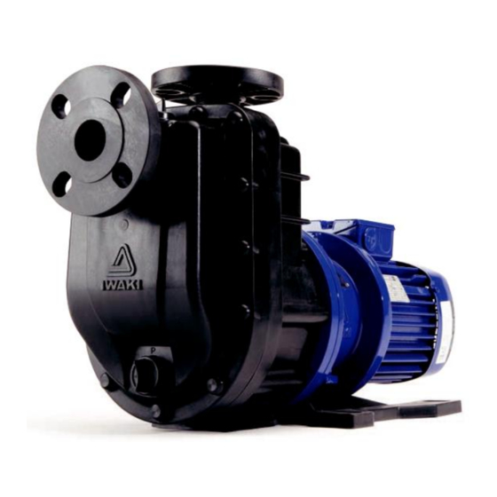
Manufacturing number 2. Product outline The SMX-F series pump is a self-priming centrifugal pump of a gas-liquid separation system. Fluoroplastic and fine ceramic wet ends are capable of handling a wide range of chemicals in various applications. Discharge Pump chamber Priming cap a. -
Page 9: Model Code
Outline 3. Model code 22 0 V V C CFRETFE type (Wet end material) 25A × 25A 40A × 40A 50A × 40A 0.4kW 0.75kW 1.5kW 2.2kW 3.7kW High density carbon/ High purity alumina ceramic/ Alumina ceramic Filled PTFE/ High purity alumina ceramic/ Alumina ceramic SiC/ SiC/ SiC EPDM 50Hz... -
Page 10: Part Names
Outline SMX-F22 4. Part names SMX-F220 MATERIAL PART NAMES Q'TY REMARKS FRONT CASE CFRETFE REAR CASE CFRETFE REAR CASING CFRETFE VOLUTE SPACER CFRETFE PLATE CFRETFE CFRETFE DRAIN CAP CFRETFE IMPELLER CFRETFE SMX-F220: FERRITE MAGNET + ALUMINIUM ALLOY DRIVE MAGNET UNIT SMX-F221: FERRITE MAGNET + DUCTILE IRON SMX-F222: REAR EARTH MAGNET + DUCTILE IRON SMX-F220, 221: FERRITE MAGNET + CFRETFE... - Page 11 Outline SMX-F44 SMX-F441 MATERIAL PART NAMES Q'TY REMARKS FRONT CASE CFRETFE REAR CASE CFRETFE REAR CASING CFRETFE VOLUTE SPACER CFRETFE PLATE CFRETFE CFRETFE DRAIN CAP CFRETFE IMPELLER CFRETFE SMX-F441: FERRITE MAGNET + DUCTILE IRON DRIVE MAGNET UNIT SMX-F442, 443: REAR EARTH MAGNET + DUCTILE IRON SMX-F441: FERRITE MAGNET + CFRETFE MAGNET CAPSULE SMX-F442, 443: REAR EARTH MAGNET + CFRETFE...
- Page 12 Outline SMX-F54 18.3 18.4 16.2 16.1 13.4 20.2 14.2 13.2 20.1 31.5 19.1 31.4 18.1 17.1 13.1 16.1 16.2 17.1 18.1 19.2 31.6 11.2 31.3 31.2 14.1 11.1 31.1 18.1 17.1 16.2 16.1 13.3 18.2 SMX-F542 MATERIAL PART NAMES Q'TY REMARKS 1+6.2 FRONT CASE UNIT CFRETFE + SM520B EQ...
-
Page 13: Overview
Outline 5. Overview Motor nameplate Pump unit Use the power voltage specified Prime the pump through the prim- on the nameplate. ing port before operation. (Follow an applicable local power regulation.) "Arrow" label Discharge port The arrow indicates a rotational Priming port direction of the motor. -
Page 14: Installation
Installation 1. Before installation ....... 13 2. Installation location ......13 3. Installation ........... 14 4. Pipework ..........15 5. Wiring ..........18 - 12 -... -
Page 15: Before Installation
Installation 1. Before installation Precautions for electrical wiring and pipework CAUTION Do not drop, hit or drag the pump during carrying in or installation. Caution Poisoning may result when handling an odorous or a harmful liquid. Keep good ventilation in a work area. The front case, rear case and base are plastics. -
Page 16: Installation
Installation 3. Installation Check if installation doesn't adversely affect facility, surrounding equipment and the pump. Install the pump according to the following instructions to ensure the optimum performance, safety and service. If the pump unit is not anchored to the foundation and if the motor unit is heavier than the pump unit, the entire pump leans towards to the motor. -
Page 17: Pipework
Installation 4. Pipework Foreign matters such as sand and scale may enter pipework while you are working. They may cause fatal damage to the pump. Be sure to blow them out before operation. Also, do not apply adhesive too much or leave a screw or nut. If pipework directory weighs on the pump, plastic parts may be deformed. - Page 18 Installation 6. Do not make an arched line in order to prevent air from being trapped. A suction line right before the pump inlet should be laid on a rising gradient of 1/100 toward the pump. 1. A discharge pipe bore is related to pipe resistance Pipe resistance rises too high to obtain an intended flow if a discharge pipe bore is too narrow.
- Page 19 Installation (This table is based on use of metal pipe flanges with rubber gaskets.) Bolt size Try not to apply a heavy load to the inlet and outlet flanges. Permissible piping weight and moment to the pump are as below. Permissible stress to outlet flange Permissible stress to inlet flange Pipe dia.
-
Page 20: Wiring
Installation 5. Wiring 1. Electrical wiring and any work on power source must be performed by qualified persons only. We are not responsi- ble for any injury and damage due to noncompliance with this notice. Contact us as necessary. 2. Install an electromagnetic switch according to motor specifications (voltage, capacity, etc.). 3. -
Page 21: Operation
Operation 1. Operational precautions ...... 20 2. Before operation ......... 21 3. Preparation ......... 23 4. Operation ..........24 - 19 -... -
Page 22: Operational Precautions
Operation 1. Operational precautions CAUTION shut off a suction valve during operation. This may damage internal parts. Prohibit . An abnor- mal sound of water flowing through a pipe or a significant pressure change (see a pressure gauge) is a sign of cavitation. Also do not continue to run the pump when air is sucked from a suction line. -
Page 23: Before Operation
Operation WARNING Do not remodel the pump A remodelled pump will not be warranted. Also, we are not responsible for personal injury or property damage due to any modification. Prohibit CAUTION Be sure to prime the pump before operation Always prime the pump when the pump is empty, for example, the pump is used for the first time or after dismantlement/assembly. - Page 24 Operation 3. ON-OFF operation Frequent ON-OFF operation damages the pump, especially in self-priming operation. Do not make ON-OFF opera- tion more than six times per hour. 4. Handled liquid - Observe the next points 1. Slurry :Slurry can not be handled. 3.
-
Page 25: Preparation
Operation 3. Preparation 1. Check the pump and pipework before operation. a. Check there are no foreign matters in the supply tank and pipework. If foreign matters are stuck in a suction line, the pump may break. Do not leave any waste of bond, sealing materials and screws/nuts as well. b. -
Page 26: Operation
Operation 4. Operation Operate the pump by the following procedure. Operation Procedure Remarks Close or open valves. Open suction valves fully. Close a discharge valve fully (in a flooded suction system). Open discharge valves fully (in a suction lift system). Prime the pump. - Page 27 Operation Remarks Operation Procedure < Points to be checked> Use a flow meter to see if the pump runs at a specified point. If a flow meter is not available, check a specified point from discharge pres- Check a flow meter and con- sure, suction pressure and current value, taking account of pipe resistance.
- Page 28 Maintenance 1. Troubleshooting ........27 2. Maintenance & Inspection....28 3. Spare & Wear parts ......32 4. Disassembly & Assembly ....35 5. Mass of pumps ........47 - 26 -...
-
Page 29: Maintenance 1. Troubleshooting
Maintenance 1. Troubleshooting If you can not find out the root cause of failure, contact us. Trouble Cause Troubleshooting Priming liquid level is too low. Stop the pump and feed a sufficient amount of priming liquid. Then restart the pump. Air enters the pump from suction line con- Check connections on a suction line. -
Page 30: Maintenance & Inspection
Maintenance Trouble Causes Troubleshooting Check that specific gravity and viscosity are The motor is overheated. suitable. The pump inlet is blocked with foreign mat- The discharge rate has dropped suddenly. ters. A suction line is blocked and this is causing Get rid of blockage. - Page 31 Maintenance Remove a residual liquid from the pump/piping and clean the inside. powders to stick to a drive and a driven magnet. cools down before it is taken apart for maintenance. 1. Always check for leakage before pump operation. Do not run the pump when liquid leaks. CAUTION The pump unit mounting bolts/nuts may loosen in the initial operation phase or under an operating condition where the temperature fluctuates greatly.
- Page 32 Maintenance To ensure efficient and smooth operation, perform periodic inspection. Be careful not to damage internal sliding parts and plastic parts when dismantling the pump. The magnetic force of a drive and a driven magnet is strong. Be careful not to catch the finger. Do not put electrical devices such as a watch and a mag card close to those magnets.
- Page 33 Maintenance Check wear degree of the bearing and spindle. Rear casing Rear thrust ring Mouth ring (SMX-F22/-F44 RF type) Impeller Impeller unit Bearing Rear thrust Magnet capsule Rear casing Magnet capsule Spindle Model SMX-F22,44 SMX-F54 Parts Dia. at shipment Wear limit Wear depth Dia.
-
Page 34: Spare & Wear Parts
Maintenance 3. Spare & Wear parts Appropriate spare parts are necessary for a long period of continuous operation. We recommend that wear parts be always in stock. Place an order for spares with the following information. 4. Part names".) 2. Pump model identification code and manufacturing number (See pump nameplate.) 3. - Page 35 Maintenance (SMX-F44) Part code Part names Material SMX-F441 SMX-F442 SMX-F443 Front case CFRETFE SMF0072 CFRETFE SMF0073 Rear case (for KK) CFRETFE SMF0074 Rear casing CFRETFE SMF0006 CFRETFE SMF0075 Volute spacer Impeller code CFRETFE SMF0076 CFRETFE SMF0092 Plate CFRETFE SMF0077 CFRETFE SMF0010 Drain cap CFRETFE...
- Page 36 Maintenance (SMX-F54) Part code Part names Material SMX-F542 SMX-F543 SMX-F545 1+6.2 Front case UNIT CFRETFE SMF0163 CFRETFE SMF0107 Rear case (for KK) CFRETFE SMF0108 Rear casing CFRETFE SMF0109 CFRETFE SMF0143 CFRETFE SMF0110 Volute spacer Impeller code CFRETFE SMF0110 CFRETFE SMF0144 CFRETFE SMF0144 Plate...
-
Page 37: Disassembly & Assembly
Maintenance 4. Disassembly & Assembly See this exploded view when dismantling/assembling the pump. Do not dismantle the pump beyond the extent of instructions in this manual. Motor shaft Motor bracket Drive magnet unit Motor Hex. socket set screw Hex head bolt Drive magnet Spring washer Hex. - Page 38 Maintenance Name SMX-22/-44 SMX-54 Remarks 1.Spanner 13mm,17mm 17mm, 19mm One each 2.Hex wrench 4mm, 8mm One each 3.T Shaped wrench 13mm 17mm 4.Flathead screw driver ×1 5.Longnose pliers ×1 6.Plastic hammper ×1 1. Remove the drain cap and drain liquid from the pump unit.
- Page 39 Maintenance 3. Remove three hex. socket head bolts which are fixing the rear casing support to rear case. Rear casing support Rear case Rear casing Cover cap 4. Remove all cover caps by using nippers. NOTE: Pinch the cylindrical body of the cap and pull it straight.
- Page 40 Maintenance in order to soften it. And then remove a spindle and a Rear casing rear thrust. Rear thrust NOTE: A rear thrust ring is attached only to (SMX-F22/-F44 RF) the SMX-F22/-F44 RF type. Do not forget to attach it. Spindle CAUTION Be careful not to burn yourself.
- Page 41 Maintenance INSPECTION If foreign matters such as iron powder stay on the magnet capsule by magnetic force, remove them. CAUTION Check that the O ring and gasket grooves are free from dust and scratches. Use new parts as necessary. 1. Fit an O ring to the drain cap and screw the cap into the drain port on the front case.
- Page 42 Maintenance 5. Combine the front case, rear case and case plate Rear case Hex socket head bolt (SMX-F54 only), and temporary tighten them by the Plate hex. socket head bolts for preventing O ring and plate Gasket Front case from moving. NOTE: Fit the case plate into the front case, Spring and then combine the front case and the...
- Page 43 Maintenance ing on the rear case. Temporarily tighten three hex. socket head bolts on the rear casing support and five stud bolts. Front case Fit rear casing support while Rear casing holding rear support casing. Rear casing 10. Tighten all bolts on tightening torque below. Attach Pump unit cover caps afterwards.
- Page 44 Maintenance NOTE: Screw two M10×50 bolts into the bracket holes until they come out about 45mm forward, mating the screw ends with the holes on rear casing support. Then start screwing down the bolts evenly in order to move the pump unit closer to the motor and finally put these components together.
- Page 45 Maintenance Impeller unit 2. Press the impeller unit into the magnet capsule unit by a handpress. At this time make sure that the through- holes on the magnet capsule comes under the U-shape holes of the impeller unit. Magnet capsule unit NOTE: Check that the end of press-fitting parts Bearing has come at a bearing surface.
- Page 46 Maintenance flathead screwdriver and then push them off. Slightly tap the end of driver handle to make it easier. Magnet capsule unit Lock pins a. Rotate in the direction of Impeller unit an arrow. b. Push off inwards. 2. The lock pins can also be turned by using the 4mm hex.
- Page 47 Maintenance 3. After the lock pins are removed, detach the impeller unit from the magnet capsule assembly by slightly tapping the back of the impeller unit with a plastic Tap the back to take it off hammer. NOTE: If the impeller unit is hardly removed, 5 minutes and tap it slightly, again.
- Page 48 Maintenance 2. After fitting the impeller unit, push the lock pins into the lock pin holes from the inside as far as it will go. degrees clockwise from the outside while holding the pins from the inside. Once it clicks, the impeller unit is secured.
-
Page 49: Mass Of Pumps
Maintenance 5. Mass of pumps The table below shows the pump weight at each model. The motor weight is not included. Model code Motor output Pump weight SMX-F220 0.37kW 14.0kg SMX-F221 0.75kW 17.0kg SMX-F222 1.5kW 17.5kg SMX-F441 0.75kW 18.5kg SMX-F442/-F443 1.5kW/2.2kW 19.0kg SMX-F542/-F543... - Page 50 - 48 -...
- Page 51 - 49 -...
- Page 52 TEL: +61 2 9899 2411 FAX: +61 2 9899 2421 Germany / IWAKI Europe GmbH Sweden / IWAKI Sverige AB China (Hong Kong) / IWAKI Pumps Co., Ltd. TEL: +49 2154 9254 50 FAX: +49 2154 9254 55 TEL: +46 8 511 72900 FAX: +46 8 511 72922...
Need help?
Do you have a question about the SMX-F Series and is the answer not in the manual?
Questions and answers