Table of Contents
Advertisement
Quick Links
Advertisement
Table of Contents

Subscribe to Our Youtube Channel
Related Manuals for IFM Electronic EFECTOR 600 TW2000


Summary of Contents for IFM Electronic EFECTOR 600 TW2000
- Page 1 Operating instructions Infrared temperature sensor TW20xx °F °C...
-
Page 2: Table Of Contents
Contents 1 General ����������������������������������������������������������������������������������������������������������������4 1�1 Information about this manual �����������������������������������������������������������������������4 1�2 Liability and Warranty ������������������������������������������������������������������������������������4 1�3 Copyright �������������������������������������������������������������������������������������������������������5 2 Safety�������������������������������������������������������������������������������������������������������������������5 2�1 Intended use ��������������������������������������������������������������������������������������������������5 2�2 User’s responsiblity ���������������������������������������������������������������������������������������5 2�3 Safety requirements ��������������������������������������������������������������������������������������5 2�4 Electromagnetic Compatibility �����������������������������������������������������������������������5 3 General Description ���������������������������������������������������������������������������������������������6 4 Function ���������������������������������������������������������������������������������������������������������������6 4�1 Switching threshold ���������������������������������������������������������������������������������������7 4�2 Output signal ������������������������������������������������������������������������������������������������7... - Page 3 11�1 Setting parameters – general information ��������������������������������������������������17 11�2 Change between the menu layers ������������������������������������������������������������18 11�3 Test function �����������������������������������������������������������������������������������������������18 11�4 Damping function ���������������������������������������������������������������������������������������19 11�5 Peak hold function �������������������������������������������������������������������������������������19 11�6 Reset all parameters to factory settings �����������������������������������������������������20 12 Operation ���������������������������������������������������������������������������������������������������������21 12�1 Display of the configuration parameters in the main menu �����������������������21 12�2 Display of the configuration parameters for advanced functions ���������������21 12�3 Ambient temperature ���������������������������������������������������������������������������������21 12�4 Error indications �����������������������������������������������������������������������������������������21...
-
Page 4: General
1 General 1.1 Information about this manual The Operating Manual shall enable the user to properly install the infrared tem- perature sensor and the required accessories� Before starting installation, be sure to read and understand this entire manual, in particular the chapter on safety! The instructions contained in this manual, especially those concerning safety, as well as site specific regulations governing UV radiation must be complied with at all times�... -
Page 5: 1�3 Copyright
1.3 Copyright This Operating Manual should be treated as confidential� It is solely intended for use by persons involved with the instrument� This manual may not be made available to a third party without prior Manufacturer’s consent� Please contact the Manufacturer if the need should arise�... -
Page 6: General Description
European certification: EN 61000-6-4 EN 61000-6-2 EN 61000-4-2/-3/-4/-6 EN 55011 When connecting a power supply unit, make sure that is also conforms to these standards� Radio interference may arise if the infrared temperature sensor is intercon-nected with such peripheral devices which have not been properly interference-suppressed�... -
Page 7: 4�1 Switching Threshold
• It generates 2 output signals according to the configured function: OUT1 Switching threshold OUT2 Analogue output 4���20 mA 4.1 Switching threshold OUT1 changes its switching status when the configured upper and lower thresh- olds (SP1, rP1) are exceeded� First set the switch point [SP1] in °C or °F� Then set the lower threshold [rP1]� When you adjust the upper threshold [SP1] the lower threshold [rP1] will change accordingly�... -
Page 8: 4�5 Switching Functions
4.5 Switching functions 1: Teperature profile 2: Switch signal Hno 3: Switch signal Hno with upper- and lower threshold delay 4: Switch signal Hnc 5: Switch signal Hnc with upper- and lower threshold delay... -
Page 9: 4�6 Internal Signal Processing
4.6 Internal signal processing Temperature ↓ Lower- / upper threshold Switch point → no / nc → delay ↓ Switching 4.7 Analogue output The infrared temperature sensor is equipped with an analogue output OUT2 4...20 mA. The maximum load is 500 Ω. Der Ausgangsstrom ist linear zur gemess- enen Temperatur� The output current is linear to the measured temperature� Within the overall measuring range, the required measuring range can be set to °C or °F using parameter [ASP2] (scale beginning) and parameter [AEP2] (scale end)�... -
Page 10: Electrical Connection
5 Electrical connection ATTENTION The infrared temperature sensor may only be installed by a skilled, qualified electrician� Do not connect the instrument while the voltage supply source is turned on� Please observe international safety regulations at all times� ► Switch to neutral and verify absence of voltage ►... -
Page 11: Shielding And Grounding
6 Shielding and Grounding 6.1 Equipotential bonding The infrared temperature sensor housing is connected to the shielding via the cable connector! Differences in ground potentials might cause an equalising current to flow between devices through a cable shielded at both ends� In this case, be sure to install an additional equipotential bonding line�... -
Page 12: Operating Controls And Display
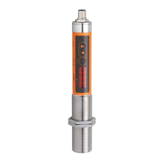
7 Operating controls and display The infrared temperature sensorr TW20xx features a 4-digit display, 3 control keys and 3 LEDs� The instrument's display panel shows the measured temperature 1 to 3: Indicator-LEDs LED 1 = indicates switching output of the respective output LED 2 = temperature in °F LED 3 = temperature in °C 4: Control key Enter... -
Page 13: Menu
8 Menu 8.1 Display of measurement reading ↓ Main menu 8.2 Main menu ↑ Display of measurement reading ↓ Advanced functions... -
Page 14: 8�3 Advanced Functions
8.3 Advanced functions ↑ Main menu... -
Page 15: Menu Explanation
9 Menu explanation 9.1 Main menu Parameter Function Comments OUT1 Upper threshold Upper threshold which activates OUT1 OUT1 Lower threshold Lower threshold which activates OUT1 ASP2 OUT2 Beginning of range Analogue start value for the range of OUT2 OUT 2 End of range Analogue end value for the range of OUT2 AEP2 Advanced functions... -
Page 16: Setup
10 Setup The infrared temperature sensor uses the intensity of infrared radiation for non- contact temperature measurements� It is necessary to configure the infrared tem- perature sensor to the respective emissivity coefficient of the measuring object to obtain exact measuring results (→ 13 Emissivity coefficient tables). An incorrectly set emissivity coefficient leads to wrong temperature readings� Set the emissivity coefficient after connecting the supply voltage or resetting the parameters to factory settings�... -
Page 17: Operating Parameters
11 Operating parameters When you reset/adjust the operating parameters the instrument remains in run mode� It continues to operate, using the current parameter settings, until you have finished configuring by pressing [Enter]� 11.1 Setting parameters – general information Select parameter ►... -
Page 18: 11�2 Change Between The Menu Layers
Adjust additional parameters ► Start again with step 2� Exit operating parameters layer ► Wait 30 s ► Switch over [▲] or [▼] from the advanced functions menu to the main menu, from the main menu to the measurement reading� The instrument features a keylock� Activate/deactivate the keylock as fol- lows: ► Press key [▲▼] simultaneously and hold them down for 10 sec. > The display shows loc or unlock for 1 sec � If you press both keys [▲▼] only briefly, you will exit the layer (ESC func- tion)�... -
Page 19: 11�4 Damping Function
If the diagnostics function is activated using the control keys on the instrument, it will remain in this mode for 10 sec� If the diagnostics function is not used, connect the diagnostics input (Pin 5) to minus� As an alternative, use a 4-pole cable box where Pin 5 is not assigned�... -
Page 20: 11�6 Reset All Parameters To Factory Settings
OUT2 [mA] 1: Measuring object in front of infrared temperature sensor 2: Hold time 3: second internal hold time 4: Measuring readings with peak hold function 5: Measuring readings without peak hold function 11.6 Reset all parameters to factory settings ►... -
Page 21: Operation
12 Operation After connecting the supply voltage the infrared temperature sensor will be automatically initialized and will perform a self-diagnosis. After approx. 0.5 sec the sensor is ready to operate and the instrument runs the signal processing� 12.1 Display of the configuration parameters in the main menu ► Press [Enter] to access the main menu ►... -
Page 22: Ways To Determine Emissivity
Display ot alternately shows overtempera- ture and measurement reading at = 0.5 Hz. Overtemperature The corresponding LED flashes at 4 Hz when the output is switched off� Incorrect connection of sup- Switching output LED flashes at 2 Hz. ply voltage LED, display, switching output and analogue Supply voltage output are deactivated.(When voltage ≥ 16 ≤ approx. 16 V V the device switches on and the switching outputs are activated)� Temperature below lower threshold The display shows UL�... -
Page 23: 13�1 Emissivity Coefficient Tables
Using a reference emissivity coefficient Apply matte black colour to a part of the surface to be measured� This part has an emissivity of 94 %� At first, measure the temperature of the coloured part� Then make a comparative measurement right next to the coloured part and adjust the emissivity on the pyrometer until it displays the previous measurement reading again�... - Page 24 Model TW2000 Copper, oxidized Leather 75���80 Marble Brass, oxidized 56���64 Paper 70���94 Sand Fireclay Steel, stainless Steel, rusty Textiles 75���88 Water 92���98 Cement Bricks 93���96 Model TW2001 / TW2011 TW2002 Wavelength λ 1,1...1,7 μm 0,78...1,06 μm "Black body" Aluminium, polished Aluminium, filed smooth Asbestos cement Bronze, polished Bronze, filed smooth Chromium, polished...
-
Page 25: Maintenance
Model TW2001 / TW2011 TW2002 Porcelain, rough Soot Fireclay Slag Pottery, glazed Bricks Zinc 14 Maintenance 14.1 Cleaning the pyrometer lens A false temperature reading will be given when the lens is dirty� Therefore, check the lens periodically and clean it, if necessary� Dust can be removed by simply blowing it away or by using a soft brush�... -
Page 26: 15�2 Packaging
15.2 Packaging The packages used are made of carefully selected, environmentally compatible materials and are thus recyclable� Please ensure that they are disposed of in an ecologically sound manner� 16 Copyright The device software contains portions of the avr-libc library� Portions of avr-libc are Copyright (c) 1999-2007 Keith Gudger, Theodore A�... -
Page 27: Default Settings (Factory Settings)
DATA, OR PROFITS; OR BUSINESS INTERRUPTION) HOWEVER CAUSED AND ON ANY THEORY OF LIABILITY, WHETHER IN CONTRACT, STRICT LIABILITY, OR TORT (INCLUDING NEGLIGENCE OR OTHERWISE) ARISING IN ANY WAY OUT OF THE USE OF THIS SOFTWARE, EVEN IF ADVISED OF THE POSSIBILITY OF SUCH DAMAGE� 17 Default settings (factory settings) Parameter Default parameters...
Need help?
Do you have a question about the EFECTOR 600 TW2000 and is the answer not in the manual?
Questions and answers