Sign In
Upload
Download
Table of Contents
Contents
Add to my manuals
Delete from my manuals
Share
URL of this page:
HTML Link:
Bookmark this page
Add
Manual will be automatically added to "My Manuals"
Print this page
×
Bookmark added
×
Added to my manuals
Manuals
Brands
IFM Electronic Manuals
Accessories
PN2 Series
Operating instructions manual
IFM Electronic PN2 Series Operating Instructions Manual
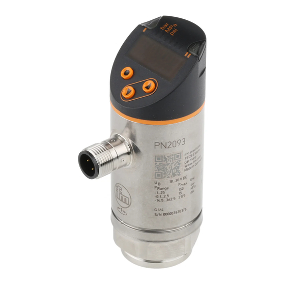
Electronic pressure sensor
Hide thumbs
1
Table Of Contents
2
3
4
5
6
7
8
9
10
11
12
13
14
15
16
17
18
19
20
21
22
23
24
25
26
27
28
29
30
31
32
33
34
35
page
of
35
Go
/
35
Contents
Table of Contents
Bookmarks
Table of Contents
Table of Contents
Preliminary Note
1�1 Symbols Used
Safety Instructions
Functions and Features
3�1 Applications
Function
4�1 Operating Modes
4�2 Communication, Parameter Setting, Evaluation
4�3 Switching Function
4�4 Analogue Function
4�5 IO-Link
4�5�1 General Information
4�5�2 Functions Only Available Via IO-Link Communication
Installation
Electrical Connection
Operating and Display Elements
Menu
8�1 Menu Structure: Main Menu
8�2 Explanation of the Menu
8�2�1 Explanation of Menu Level 1
8�2�2 Explanation of Menu Level 2
Parameter Setting
9�1 Parameter Setting in General
9�2 Define Operating Mode (Optional)
9�3 Configure Display (Optional)
9�4 Set Output Signals
9�4�1 Set Output Functions
9�4�2 Define Switching Limits for the Hysteresis Function
9�4�3 Define Switching Limits for the Window Function
9�4�4 Scale Analogue Value
9�5 User Settings (Optional)
9�5�1 Set Delay Time for the Switching Outputs
9�5�2 Set Output Logic for the Switching Outputs
9�5�3 Set Damping for the Switching Signal
9�5�4 Set Damping for the Analogue Output
9�5�5 Zero-Point Calibration
9�5�6 Reset All Parameters to Factory Setting
9�5�7 Set Colour Change of the Display
9�5�8 Graphical Depiction of the Colour Change of the Display
9�6 Diagnostic Functions
9�6�1 Read Min/Max Values for the System Pressure
Operation
10�1 Read Set Parameters
10�2 Self-Diagnostics / Fault Indications
Technical Data
11�1 Setting Ranges
11�1�1 Setting Ranges in Operating Mode 2
11�1�2 Setting Ranges in Operating Mode 3
Factory Setting
Advertisement
Quick Links
1
4�1 Operating Modes
2
4�2 Communication, Parameter Setting, Evaluation
3
4�4 Analogue Function
4
9�1 Parameter Setting in General
Download this manual
Operating instructions
Electronic pressure sensor
UK
UK
PN2
Table of
Contents
Previous
Page
Next
Page
1
2
3
4
5
Advertisement
Table of Contents
Need help?
Do you have a question about the PN2 Series and is the answer not in the manual?
Ask a question
Questions and answers
Related Manuals for IFM Electronic PN2 Series
Accessories IFM Electronic PY2954 Operating Instruction
Combined pressure sensor (19 pages)
Accessories IFM Electronic PA32xx Series Installation Instructions Manual
Electronic pressure sensor (6 pages)
Accessories IFM Electronic PN5 series Operating Instructions Manual
Electronic pressure sensor (33 pages)
Accessories IFM Electronic PN7000 Operating Instructions Manual
Pn70 series pressure sensor (19 pages)
Accessories IFM Electronic Efectorsod PM2053 Operating Instructions Manual
Electronic pressure sensor, pm205 series (13 pages)
Accessories IFM Electronic PN72 Series Operating Instructions Manual
Electronic pressure sensor (25 pages)
Accessories IFM Electronic PY995 Series Operating Instructions Manual
Electronic pressure sensor (38 pages)
Accessories IFM Electronic PI7093 Operating Instructions Manual
Electronic pressure sensor (21 pages)
Accessories IFM Electronic PN50 Series Operating Instructions Manual
Pressure sensor (17 pages)
Accessories IFM Electronic PN5004 Operating Instructions Manual
Pressure sensor (17 pages)
Accessories IFM Electronic efectro 500 Operating Instructions Manual
Pressure sensor (17 pages)
Accessories IFM Electronic PN2094 Operating Instructions Manual
Electronic pressure sensor (35 pages)
Accessories IFM Electronic PB7 Operating Instructions Manual
Electronic pressure sensor (23 pages)
Accessories IFM Electronic PI209 Series Operating Instructions Manual
Electronic pressure sensor (21 pages)
Accessories IFM Electronic Efectorsod PE70 Series Operating Instructions Manual
Pressure sensor (17 pages)
Accessories IFM Electronic LR3000 Operating Instructions Manual
Electronic level sensor (30 pages)
This manual is also suitable for:
Pn2093
Pn2593
Pn2092
Pn2592
Pn2071
Pn2571
...
Show all
Pn2070
Pn2570
Pn2160
Pn2560
Pn2094
Pn2594
Pn2096
Pn2596
Pn2097
Pn2597
Pn2099
Pn2599
Pn2169
Pn2569
Pn2098
Pn2598
Table of Contents
Save PDF
Print
Rename the bookmark
Delete bookmark?
Delete from my manuals?
Login
Sign In
OR
Sign in with Facebook
Sign in with Google
Upload manual
Upload from disk
Upload from URL


Need help?
Do you have a question about the PN2 Series and is the answer not in the manual?
Questions and answers