
Related Manuals for IFM Electronic efector 800 VSE100


Summary of Contents for IFM Electronic efector 800 VSE100
- Page 1 Operating instructions Diagnostic electronics for vibration sensors VSE100 VYE102 VYE107...
-
Page 2: Table Of Contents
Contents 1 Preliminary note ���������������������������������������������������������������������������������������������������3 2 Safety instructions �����������������������������������������������������������������������������������������������3 3 Functions and features ����������������������������������������������������������������������������������������3 4 Installation������������������������������������������������������������������������������������������������������������5 4�1 Installation of the sensors ������������������������������������������������������������������������������5 5 Electrical connection ��������������������������������������������������������������������������������������������5 5�1 Limited voltage / current ��������������������������������������������������������������������������������6 5�2 Wiring�������������������������������������������������������������������������������������������������������������6 5�2�1 Wiring of the sensors 1���4 (S1���S4) according to the sensor ��������������7 5�3 Connection of the sensors �����������������������������������������������������������������������������8 5�3�1 Monitoring the sensor cable �����������������������������������������������������������������8 5�4 Ethernet connection ���������������������������������������������������������������������������������������9... -
Page 3: Preliminary Note
The final function depends on the firmware version� The current firmware and operating software can be downloaded from the download area on ifm electronic's website�... - Page 4 • An analogue current signal or a pulse signal can be connected to the analogue inputs� They can be used as speed input for vibration diagnostics, as trigger of a measurement or for process value monitoring� • An analogue current signal can also be connected to the dynamic inputs to monitor max�...
-
Page 5: Installation
Via the Ethernet interface of the diagnostic electronics networking is possible to visualise data (measured values, alarm states, ���) in other systems (e�g� SCADA, MES, ����)� The type VOS OPC server from ifm is a suitable optional accessoring� The device is not approved for safety-related tasks in the field of operator protection� 4 Installation Mount the unit in a control cabinet with a protection rating of at least IP 54 to ensure protection against accidental contact with dangerous contact voltages... -
Page 6: 5�1 Limited Voltage / Current
The outputs are short-circuit proof� The outputs can be configured as either normally closed or normally open� In addition an analogue signal can be provided on output [OU 1] (0/4���20 mA) or [U-OUT] (0���10 V) (e�g� acceleration values)� 5.1 Limited voltage / current According to UL508 the device shall be supplied from an isolating source having a secondary UL-listed fuse rated a) max 5 A for voltages 0���20 Vrms (0���28�3 Vp) or... -
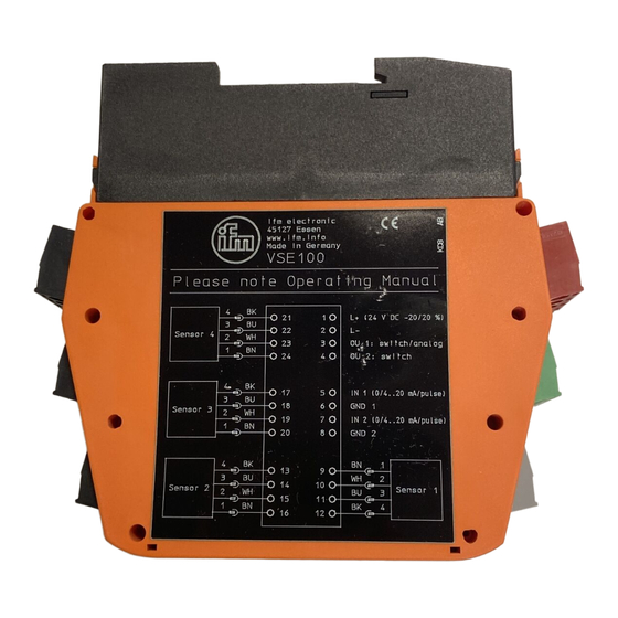
Page 7: 5�2�1 Wiring Of The Sensors 1
Terminal Connection Description If a VSP or IEPE sensor is used 24 V DC ± 20 % OU 1 Early warning output OU 2 Main alarm output IN 1 Process value input 1 GND1 IN 2 Process value input 2 GND 2 5.2.1 Wiring of the sensors 1...4 (S1...S4) according to the sensor Sensor input... -
Page 8: 5�3 Connection Of The Sensors
5.3 Connection of the sensors ► Adhere to the SELV criteria when the sensors are connected so that no dangerous contact voltages are applied to the sensor or transferred to the device! Sensor and diagnostic electronics supply are not electrically isolated� 5.3.1 Monitoring the sensor cable In case of wire break, short circuit or faulty measuring cell: • the output [OU 1] provides 22 mA (±... -
Page 9: 5�4 Ethernet Connection
5.4 Ethernet connection The RJ45 socket is used for the connection to the Ethernet� Ethernet cables can be supplied as accessories, e.g.: cross-over cable, 2 m, article no� EC2080 cross-over cable, 5 m, article no� E30112 6 Operation The input signals are continuously detected and permanently monitored according to the set tasks (parameters)�... -
Page 10: Indicators (Leds)
7 Indicators (LEDs) LED 1 for sensor 1 Lights green Sensor connected and configured Flashes green Sensor is configured; LED 1 type VSA LED 2 sensor is not connected LED 3 or faulty LED 4 TYPE IEPE LED 5 Sensor not connected Lights yellow Early warning Lights red... -
Page 11: Maintenance, Repair And Disposal
8 Maintenance, repair and disposal If used correctly, no maintenance and repair measures are necessary� Only the manufacturer is allowed to repair the unit� After use dispose of the unit in an environmentally friendly way in accordance with the applicable national regulations�...
Need help?
Do you have a question about the efector 800 VSE100 and is the answer not in the manual?
Questions and answers