Challenger Lifts 44030 Installation, Operation & Maintenance Manual
Heavy duty four post lift
Hide thumbs
Also See for 44030:
- Installation, operation & maintenance manual (25 pages) ,
- Installation, operation & maintenance manual (25 pages)
Table of Contents
Advertisement
I
, O
&
NSTALLATION
PERATION
M
M
AINTENANCE
ANUAL
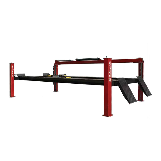
Heavy Duty
Four Post Lift
M
44030
ODEL
Standard and Extended
30,000 lbs Capacity
2311 South Park Rd Louisville, Kentucky 40219
Email:sales@challengerlifts.com
Web
site:www.challengerlifts.com
Office 800-648-5438 / 502-625-0700 Fax 502-587-1933
IMPORTANT:
READ THIS MANUAL COMPLETELY
BEFORE INSTALLING or OPERATING LIFT
06/11/2020
Advertisement
Table of Contents

Related Manuals for Challenger Lifts 44030


Summary of Contents for Challenger Lifts 44030
- Page 1 & NSTALLATION PERATION AINTENANCE ANUAL Heavy Duty Four Post Lift 44030 ODEL Standard and Extended 30,000 lbs Capacity 2311 South Park Rd Louisville, Kentucky 40219 Email:sales@challengerlifts.com site:www.challengerlifts.com Office 800-648-5438 / 502-625-0700 Fax 502-587-1933 IMPORTANT: READ THIS MANUAL COMPLETELY BEFORE INSTALLING or OPERATING LIFT...
-
Page 2: Table Of Contents
Installation, Operation and Maintenance Manual for the Model 44030 TABLE OF CONTENTS Important Information Cautions and Warnings Tools Required Anchoring Tips Installation Instructions 30 Day Maintenance Trouble Shooting Guide Parts & Shipping List Parts Breakdown and Installation Drawings Rev 06/11/2020... -
Page 3: Important Information
Installation, Operation and Maintenance Manual for the Model 44030 IMPORTANT INFORMATION 1. The floor where the lift is to be installed must be a minimum of 4” thickness of concrete. Concrete must be reinforced with steel rebar with a minimum compressive strength of 3,000 psi . -
Page 4: Tools Required
Installation, Operation and Maintenance Manual for the Model 44030 TOOLS REQUIRED Concrete rotary hammer drill with ¾” carbide bit Open End Wrenches: 7/16”, 1/2”, 9/16”, 11/16”, 3/4” & 1 1/8” Ratchet Driver Sockets: ¼”, 1/2”, 3/4” X 1/2” deep Allen Wrenches: 3/16”, 1/4” & 5/16”... -
Page 5: Anchoring Tips
Installation, Operation and Maintenance Manual for the Model 44030 ANCHORING TIPS 1. Anchor must be at least 5” from the edge of the slab or any seam. 2. Use a concrete hammer drill with a 3/4” carbide bit. 3. Do not use a worn bit. -
Page 6: Installation Instructions
Installation, Operation and Maintenance Manual for the Model 44030 INSTALLATION INSTRUCTIONS 1. Standard area required for four post alignment lift is a minimum of (STD.) 15’-6” x 30’-0”’ or (EXT.) 15’-6” x 35’-0” area. If 3 feet track extensions are purchased then increase the length in increments of the 3’-0”... - Page 7 Installation, Operation and Maintenance Manual for the Model 44030 9. Next locate a Cross Rail assembly. Use a fish tape to pull the Cross Rail chain through the Cross Rail tube. The chain runs under the roller on the offside and over the roller on the Mainside.
- Page 8 Installation, Operation and Maintenance Manual for the Model 44030 19. Step #10 is to connect the 3/8 hydraulic hose from the power unit to the cylinder. Next secure the 3/8 hydraulic hose using the ¾ rubber cushion steel loop (4 pcs. – 3225T6) and #10 x ½...
-
Page 9: 30 Day Maintenance
Installation, Operation and Maintenance Manual for the Model 44030 30 DAY MAINTENANCE 1) Check all bolts and nuts to make sure the are tight. 2) Check equalizer chains regularly for proper tension and adjustment. 3) Inspect adapters and pads for damage or wear. Replace if necessary. -
Page 10: Trouble Shooting Guide
Installation, Operation and Maintenance Manual for the Model 44030 TROUBLE SHOOTING GUIDE POSSIBLE PROBLEM POSSIBLE CAUSE & SOLUTIONS 1. MOTOR DOES NOT RUN A) Breaker tripped or fuse blown B) Motor thermal overload tripped. Wait for overload to cool. C) Check thermal overload in starter box (three phase only). -
Page 11: Parts & Shipping List
Installation, Operation and Maintenance Manual for the Model 44030 PARTS & SHIPPING LIST PART NUMBER DESCRIPTION QTY. 5304ZZ 52 O.D. x 20 I.D. x 22W DS Bearing 90126A036 ¾ SAE Flat Washer 90126A037 7/8 SAE Flat Washer 98410A128 3/4 Dia. Retainer Ring 98410A131 7/8 Dia. - Page 12 Installation, Operation and Maintenance Manual for the Model 44030 ALIF-430-074 Cylinder Bosses ALIF-430-076 Safety Latch Pin PART NUMBER DESCRIPTION QTY. ALIF-430-078 Cross Rail Bearing Pin ALIF-430-084 Cross Rail Chain Connector ALIF-430-087 BL844, 216 Pitch M & F Ends, Cross Rail Chain GL-12-056 4”...
- Page 13 Installation, Operation and Maintenance Manual for the Model 44030 PART NUMBER DESCRIPTION QTY. ARTS 414411000 3-Way Pneumatic Control Valve 3225T6 ¾ Rubber-Cushion Steel Loop 5402-02-04 1/4FNPT X 1/8MNPT Expander 6534K46 ¼ MNPT Pneumatic Hose Coupling 6801-LL-06-06 3/8 MJIC x 3/8 MORB 90 Deg. Fitting 90096A242 #10-24 x ½...
- Page 25 Installation, Operation and Maintenance Manual for the Model 44030 REVISIONS 06/11/2020- UPDATED ADDRESS AND COVER PAGE Rev 06/11/2020 44030-IOM-A.doc...
Need help?
Do you have a question about the 44030 and is the answer not in the manual?
Questions and answers