Advertisement
Installation, Operation & Maintenance Manual
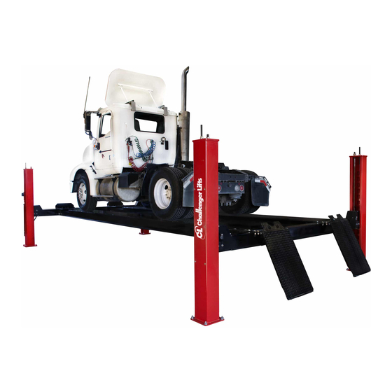
Four Post
Surface Mounted Lift
Model 4030
(30,000 lb Capacity)
2311 South Park Rd, Louisville, Kentucky 40219
Email:
Web site:
sales@challengerlifts.com
www.challengerlifts.com
Office 800-648-5438 / 502-625-0700 Fax 502-587-1933
IMPORTANT:
READ THIS MANUAL COMPLETELY BEFORE
INSTALLING or OPERATING LIFT
Rev. 5/22/19
Advertisement
Table of Contents

Subscribe to Our Youtube Channel
Related Manuals for Challenger Lifts 4030SFX


Summary of Contents for Challenger Lifts 4030SFX
- Page 1 Installation, Operation & Maintenance Manual Four Post Surface Mounted Lift Model 4030 (30,000 lb Capacity) 2311 South Park Rd, Louisville, Kentucky 40219 Email: Web site: sales@challengerlifts.com www.challengerlifts.com Office 800-648-5438 / 502-625-0700 Fax 502-587-1933 IMPORTANT: READ THIS MANUAL COMPLETELY BEFORE INSTALLING or OPERATING LIFT Rev.
-
Page 2: General Specifications
Model 4030 Installation, Operation and Maintenance ENERAL PECIFICATIONS : 4030[E X] [A F] [O ODEL LENGTH ALIGN OR FLAT DECK OPEN OR CLOSED FRONT 4030EAX 4030XAX 4030SFX 4030XFX 4030SAX 4030EFX SPECIFICATIONS 308” 344” 380” 308” 344” 380” Length Overall 172.75”... - Page 3 Model 4030 Installation, Operation and Maintenance ERTICAL LEARANCE AFETY OTICES AND ECALS Check the height of the area where the lift is to be For your safety, and the safety of others, read and installed. Clearance should be calculated based on understand all of the safety notices and decals the full raised height of the lift.
-
Page 4: Installation
Do this for your own 7430-0506 WHEEL CHOCK protection. AB-100157 POWER UNIT NOTIFY Challenger Lifts AT ONCE if any hidden 9430-0308 POWER RUNWAY ASSEMBLY loss or damage is discovered after receipt. 8430-0334 IDLE RUNWAY ASSEMBLY IT IS DIFFICULT TO COLLECT FOR LOSS OR... - Page 5 Model 4030 Installation, Operation and Maintenance 3) Position runways on blocking, see Fig 5, per layout lines established in step 1. Use four 30” long 4x4’s spanning the width of the runway. Cables #3 and #4 should be extending out from the rear of the power runway and cables #1 and #2 from the front of the power runway, Fig 5.
- Page 6 Model 4030 Installation, Operation and Maintenance Fig 6 - Cross Rail Assembly Rev. 5/22/2019 4030-IOM-A.doc...
- Page 7 Model 4030 Installation, Operation and Maintenance 7) Attach both cross beams to the runways (Fig. 4) using 3/4"-16,2.5" Length Steel Hex Cap Screws, ZC-PLTD, a 3/4" screw size washer on the bolt head side, and nut side. secure with a 3/4"-16 GRADE 8 STEEL NYLON- INSERT LOCKNUT.
- Page 8 Model 4030 Installation, Operation and Maintenance NCHORING 15) The anchor bolts must be installed at least 8” from any crack, edge, or expansion joint. Also, at least 16” from any other lifts hole. 16) Use a concrete hammer drill with a 3/4-inch carbide bit.
-
Page 9: Wiring Diagram
Model 4030 Installation, Operation and Maintenance Wiring Diagram FOR SINGLE PHASE (Normally Open) FIELD CONECTIONS Fig 15 – Electrical Wiring Diagram 26) B lubricated, and regulated to 90-120 psi. The ERTAIN ITTINGS AND ONNECTIONS FRL, must be within 30 feet of valve. Failure to IGHT T IS THE INSTALLERS RESPONSIBILITY . - Page 10 Model 4030 Installation, Operation and Maintenance 41) Lower lift and raise to check for lock engagement. locks should engage simultaneously (clicking noise). Re-adjust cables as needed to synchronize locks. 42) Position Front Turn Plates (SOLD SEPARATELY) and install TURN TABLE STOPS (ITEM 1 PART NUMBER ALIG-430- 029-XX) to runway using (8, ITEM 2) #10-24 x 0.75”...
-
Page 11: Operation Procedure
Model 4030 Installation, Operation and Maintenance The Owner/Employer shall display the lift PERATION ROCEDURE manufacturer’s operating instructions; ALI/SM 93 - 1, ALI Lifting It Right safety manual; ALI/ST-90 ALI AFETY OTICES AND ECALS Safety Tips card; ANSI/ALI ALOIM-2008, American This product is furnished with graphic safety National Standard for Automotive Lifts-Safety warning labels, which are reproduced on page 3 Requirements... - Page 12 Model 4030 Installation, Operation and Maintenance IFTING A EHICLE AINTENANCE Drive vehicle onto lift. Set parking brake and/or use To avoid personal injury, permit only qualified wheel chocks that are provided with lift. personnel to perform maintenance on this equipment. Maintenance personnel should follow When the vehicle has reached the desired working lockout/tag out instructions per ANSI Z244.1.
-
Page 13: Parts Breakdown
Model 4030 Installation, Operation and Maintenance Parts Breakdown Fig A. General Layout Rev. 5/22/2019 4030-IOM-A.doc... - Page 14 5/8” WASHER 40126 1/8” X 1-1/2” COTTER PIN Replace all worn, damaged, or broken parts with parts approved by Challenger Lifts Inc. or with parts meeting Challenger Lifts Inc. specifications. Contact your local Challenger Lifts Parts Distributor for pricing and availability.
- Page 15 98023A039 1-1/8" ID, WASHER, ZC, GR 8 Replace all worn, damaged, or broken parts with parts approved by Challenger Lifts Inc. or with parts meeting Challenger Lifts Inc. specifications. Contact your local Challenger Lifts Parts Distributor for pricing and availability.
- Page 16 94895A865 1-1/2"-12 ZC YW-CHRME PLT STEEL HEX NUT, GR 8 Replace all worn, damaged, or broken parts with parts approved by Challenger Lifts Inc. or with parts meeting Challenger Lifts Inc. specifications. Contact your local Challenger Lifts Parts Distributor for pricing and availability.
- Page 17 Model 4030 Installation, Operation and Maintenance PARTS BREAKDOWN (continued) Fig D. Cross Beam Rev. 5/22/2019 4030-IOM-A.doc...
- Page 18 1/2”-13, 3/4” LENGTH HEX SCREW, ZC, GR8 91102A033 1/2" LOCK WASHER Replace all worn, damaged, or broken parts with parts approved by Challenger Lifts Inc. or with parts meeting Challenger Lifts Inc. specifications. Contact your local Challenger Lifts Parts Distributor for pricing and availability.
- Page 19 1/8 MNPT X 1/8 FNPT 90 DEGREE STREET ELBOW SPE-25 AIRLINE T Replace all worn, damaged, or broken parts with parts approved by Challenger Lifts Inc. or with parts meeting Challenger Lifts Inc. specifications. Contact your local Challenger Lifts Parts Distributor for pricing and availability.
- Page 20 Model 4030 Installation, Operation and Maintenance NOTES: Rev. 5/22/2019 4030-IOM-A.doc...
Need help?
Do you have a question about the 4030SFX and is the answer not in the manual?
Questions and answers