Advertisement
Quick Links
Instructions
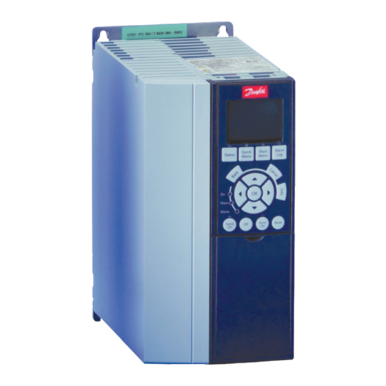
Frequency converter CD302
Inverter reciprocating compressors VTZ
Safety instructions and General Warning
Disposal
Drive:
Equipment containing electrical com-
ponents may not be disposed together
with domestic waste.
It must be separate collected with Electrical and
Electronic Waste according to local and currently
valid legislation.
Compressors:
Danfoss recommends not to thriw away a used
compressor but to a dispose of the compressor
and its oil at a specialised recycling company site
Caution
The CD 302 Compressor Drive™ DC link capa-
citors remain charged after power has been dis-
connected. To avoid an electrical shock hazard,
disconnect the CD 302 from the mains before
carrying out maintenance. Wait at least as follows
before doing service on the frequency converter:
CD 302:
≤ 7.5 kW 4 minutes
CD 302:
11 . 22 kW 15 minutes
Be aware that there may be high voltage on the
DC link even when the LEDs are turned off.
CD302 Operating Instructions Software version:
1.0x
These Operating Instructions can be used for all
CD302 Compressor Drives™ with software version
1.0x.
The software version number can be seen from
parameter 15-43.
High Voltage Warning
The voltage of the CD 302 is dangerous
© Danfoss | DCS (CC)| 2019.04
whenever the converter is connected to mains.
Incorrect fitting of the motor or frequency
converter may cause damage to the equipment,
serious injury or death. Consequently, it is essen-
tial to comply with the instructions in this manual
as well as local and national rules and safety regu-
lations.
Safety Instructions
• Make sure the CD 302 is properly connected to
earth.
• Do not remove mains plugs or motor plugs
while the CD 302 is connected to mains.
• Protect users against supply voltage.
• Protect the motor against overloading accor-
ding to national and local regulations.
• Motor overload protection is included in the
default settings
• The earth leakage current exceeds 3.5 mA.
• The [OFF] key is not a safety switchIt does not
disconnect the CD 302 from mains.
General warning
Warning:
Touching the electrical parts may be fatal - even
after the equipment has been disconnected from
mains.
Also make sure that other voltage inputs have
been disconnected, such as load-sharing (linkage
of DC intermediate circuit).Using CD 302 Com-
pressor Drives™: wait at least 15 minutes.
Shorter time is allowed only if indicated on the
nameplate for the specific unit.
Leakage Current
The earth leakage current from the CD 302
exceeds 3.5 mA. To ensure that the earth cable
has a good mechanical connection to the earth
connection (terminal 95), the cable cross section
must be at least 10 mm
2
or 2 times rated earth
wires terminated separately.
Residual Current Device
This product can cause a D.C. current in the
protective conductor. Where a residual current
device (RCD) is used for extra protection, only an
RCD of Type B (time delayed) shall be used on the
supply side of this product. See also RCD Applica-
tion Note MN.90.GX.02.Protective earthing of the
CD 302 and the use of RCD.s must always follow
national and local regulations.
IT Mains
Do not connect 400 V frequency converters
with RFI-filters to mains supplies with a Voltage
between phase and earth of more than 440 V. For
IT mains and delta earth (grounded leg), mains
voltage may exceed 440 V between phase and
earth.
Par. 14-50 RFI 1 can on CD 302 be used to dis-
connect the internal RFI capacitors from the RFI
filter to ground. If this is done it will reduce the RFI
performance to A2 level.
Before Commencing Repair Work
1. Disconnect CD 302 from mains
2. Disconnect DC bus terminals 88 and 89
3. Wait for discharge of the DC-link. See period of
time on the warning label.
4. Remove motor cable
Avoid Unintended Start
While CD 302 is connected to mains, the motor
can be started/stopped using digital commands,
bus commands, references or via the Local
Control Panel (LCP).
• Disconnect the CD 302 from mains whenever
personal safety considerations make it necessary
to avoid unintended start.
• To avoid unintended start, always activate the
[OFF] key before changing parameters.
• An electronic fault, temporary overload, a fault
in the mains supply, or lost motor connection
AN000086420674en-000201 | 1
Advertisement

Related Manuals for Danfoss CD302


Summary of Contents for Danfoss CD302
- Page 1 • Do not remove mains plugs or motor plugs Do not connect 400 V frequency converters Danfoss recommends not to thriw away a used while the CD 302 is connected to mains. with RFI-filters to mains supplies with a Voltage compressor but to a dispose of the compressor •...
-
Page 2: Digital Output
1) Terminal 27 and 29 can also be programmed as Mechanical Installation input. Digital inputs Find the following parts included in the CD302 The digital output is galvanically isolated from the • Voltage level: 0 - 24 V DC Accessory Bag. - Page 3 Because of the need for cooling, there must be a minimum of 100 mm free air passage above and below the CD 302. The back wall must always be solid. All CD302 are equiped of a back metal plate to garantee proper heat exchanger ventilation. Never remove this metal sheet.
-
Page 4: Power Input
For more information, see EMC specifica- cation manual. tions. - Use a screened/armoured motor compressor - Fasten decoupling plate to the bottom of CD302 cable to comply with EMC emission specifica- with screws and washers from the accessory bag. tions. - Page 5 • Electrical motor compressor protection • Access to Control Terminals The electrical motor compressor protection is fully provided by the CD302 frequency converter. - CD302 makes through an Electronic current measurement anti-overload and lock-rotor motor compressor protection (see description in the application manual).
- Page 6 3. Insert the cable in the adjacent circular hole. minal 12/13) 4. Remove the screw driver. The cable is now mounted to the terminal. Default settings: 18 = start 27 = coast inverse 37 = safe stop inverse 6 | AN000086420674en-000201 © Danfoss | DCS (CC) | 2019.04...
- Page 7 Instructions Diagram showing all electrical terminals. supply cables. connected separately to the CD302 common Terminal 37 is the input to be used for Safe Stop. If this occurs, you may have to break the screen inputs (terminal 20, 55, 39) to avoid ground cur-...
- Page 8 IP 20 frequency converter. The frequency converter is fitted in an installation cabinet with an output contactor and connected to a PLC, which is installed in a separate cabinet. 8 | AN000086420674en-000201 © Danfoss | DCS (CC) | 2019.04...
- Page 9 EMC test results. • EMC Correct Installation of an IP20 CD302 • Safety earth connection The earth leakage current from the frequency section must be at least 10 mm2 or 2 rated earth The frequency converter has a high leakage cur- converter exceeds 3.5 mA.
- Page 10 Process Control via an AKS32 Frequency converter CD302 Compressor Drive Digital output Analog Analog output input Start to external fault relay Process Control via an AKS33 10 | AN000086420674en-000201 © Danfoss | DCS (CC) | 2019.04...
- Page 11 NB: When running high voltage tests of the entire After installation and before first operation, 3. Then reapply 24 V DC to terminal 37. The test installation, CD302 compressor Drive and com- perform a commissioning test of an installation step is passed if the motor compressor remains in pressor electrical motor compressor test can be or application making use of CD 302 Safe Stop.
- Page 12 Error(s) Check VTZ Come back to factory Motor settings Correct Incompatibility the fault Between Software & Additional option Mains shut-off before checking Contact your Local Danfoss Reset & Start 12 | AN000086420674en-000201 © Danfoss | DCS (CC) | 2019.04...
- Page 13 Start failed Micro network Minimum speed not reached after shortage 2sec. Compressor stopped Compressor stopped Automatic restart after 30 s Automatic restart after 30 s 10 restarts before blocage (20 possible) © Danfoss | DCS (CC) | 2019.04 AN000086420674en-000201 | 13...
- Page 14 1) Connect the power supply to the terminals (L1, mitter (4-20 mA for example is the factory set- L2 and L3) of the CD302 as shown on page 7 of ting). this manual.
- Page 15 Controls using a 4-20mA process signal & parameter, or function in any display window. mend that you store the data in the LCP or on a PC CD302-PID controller + Smart Logic Control [Info] provides detailed information whenever via MCT 10 Set-up Software Tool.
- Page 16 DC Link Voltage ...........[1630] - Par 6-25 Preset to 12 bar Heatsink Temp.............[1634] - Par 7-20 Preset to analog input 54 (Analog input for Inverter Thermal ..........[1635] PID control) 16 | AN000086420674en-000201 © Danfoss | DCS (CC) | 2019.04...
- Page 17 Function: levant compressor selected in Par. 1-13. These parame- Select Disabled [0] to avoid accidental start of the ters cannot be modified from the CD302 data-base. 0-65 Quick Menu Password frequency converter in Hand mode. Select Password 1-20 ..........Motor Power [kW] Function: [2] to avoid unauthorised start in Hand mode.
- Page 18 3-15 Reference Source 1, 3-16 Reference *Linked to Hand / Auto .......... [0] reference (X+X*Y/100) to give the resultant actual Source 2 or 3-17 Reference Source 3). Remote ................[1] reference. 18 | AN000086420674en-000201 © Danfoss | DCS (CC) | 2019.04...
- Page 19 Parameters: Digital In/Out Because previous settings rotation is always 6-1* Analog Input 1 clockwise (positive), but be sure that CD302 U, V, Parameter group for configuring the digital input Parameters for configuring the scaling and limits W terminals are connected to the correspondant and output.
- Page 20 Use this parameter to specify normal operation; to Option: Option: perform tests; or to initialise all parameters except par. Normal ................[0] Off ................... [0] 15-03, 15-04 and 15-05. This function is active only 20 | AN000086420674en-000201 © Danfoss | DCS (CC) | 2019.04...
- Page 21 Par. 14-22 will also revert to the default setting CD302 main parameters for VTZ Compressors” selected application. Normal operation [0]. Select Control card test [1] to test the analog and digital Smart Logic Control (SLC) is essentially a sequence inputs and outputs and the +10 V control voltage.
- Page 22 If the specified number of AUTOMATIC RESET’s is reached within 30 secondes, the frequency converter enters Ma- nual reset 14-21 Reset time 30 Sec. Interval between trip and automatic reset Par. [14-20] 22 | AN000086420674en-000201 © Danfoss | DCS (CC) | 2019.04...
- Page 23 Set desired minimum run- 13-20.1 Timer 1 (Minimum Run-time) 0 min Compressor will run for 1 min. before stopping ning time * SLC: Smart Logic Controller © Danfoss | DCS (CC) | 2019.04 AN000086420674en-000201 | 23...
- Page 24 Terminal 54 High Current (mA) 6-23 SL Controller Action 1352.4 No action Terminal 54 Low ref/Feedb.value 6-24 SL Controller Action 1352.5 Stop Terminal 54 High ref/Feedb.value 6-25 SL Controller Action 1352.6 No action 24 | AN000086420674en-000201 © Danfoss | DCS (CC) | 2019.04...
- Page 25 Terminal 53 High ref/Feedb.value 6-15 (not linked) (not linked) (not linked) (not linked) (not linked) (not linked) (not linked) © Danfoss | DCS (CC) | 2019.04 AN000086420674en-000201 | 25...
- Page 26 (not linked) as p3-02 (not linked) as p3-02 (not linked) Terminal 53 High ref/Feedb.value 6-15 as p3-03 (not linked) as p3-03 (not linked) as p3-03 (not linked) as p3-03 (not linked) 26 | AN000086420674en-000201 © Danfoss | DCS (CC) | 2019.04...
- Page 27 Terminal 53 High ref/Feedb.value 6-15 (not linked) (not linked) (not linked) (not linked) (not linked) (not linked) (not linked) © Danfoss | DCS (CC) | 2019.04 AN000086420674en-000201 | 27...
- Page 28 Danfoss can accept no responsibility for possible errors in catalogues, brochures and other printed material. Danfoss reserves the right to alter its products without notice. This also applies to products already on order provided that such alterations can be made without subsequential changes being necessary in specifications already agreed. All trade- marks in this material are property of the respective companies.
Need help?
Do you have a question about the CD302 and is the answer not in the manual?
Questions and answers