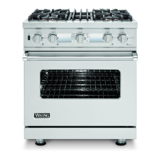
Viking VDSC548T Series Service Manual
Electronic control dual fuel range
Hide thumbs
Also See for VDSC548T Series:
- Specification sheet (8 pages) ,
- Manual (48 pages) ,
- Use & care manual (37 pages)
Table of Contents
Advertisement
Quick Links
Service
Manual
This manual is to be used by qualified appliance technicians only.
Viking does not assume any responsibility for property damage
or personal injury for improper service procedures done by an
unqualified person.
Electronic
Control Dual
Fuel Range
Preferred Service
This Base Manual covers general and
specific information including, but not
limited to the following models:
VDSC530T–4B
VDSC536T–6B
VDSC536T–4G
VDSC536T–4Q
VDSC548T–6G
VDSC548T–6Q
VDSC548T–4GQ
SMC-0012A
June, 2011
Advertisement
Table of Contents

Subscribe to Our Youtube Channel
Related Manuals for Viking VDSC548T Series


Summary of Contents for Viking VDSC548T Series
- Page 1 Preferred Service Manual This manual is to be used by qualified appliance technicians only. Viking does not assume any responsibility for property damage or personal injury for improper service procedures done by an unqualified person. This Base Manual covers general and Electronic specific information including, but not...
-
Page 2: Table Of Contents
Cycle Charts Right Oven (Hi Broil Cycle) ....29 Oven Light ..............56 Convection Fan Low Reverse ........57 Cycle Charts Right Oven (Medium Broil Cycle) ..29 Convection Fan High Reverse ........57 Cycle Charts Right Oven (Low Broil Cycle) ...29 © 2011 Viking Preferred Service... - Page 3 Wiring Schematic–VDCS548T-4GQ/6G Landing Ledge–VDSC548T ........90 Right Oven ............. 131 Left Oven Thermostat–VDSC548T ......92 Wiring Schematic–VDCS548T-6Q–RIght Oven ..132 Left Oven Function Selector–VDSC548T ....92 Char-Grill–VDSC536T-4Q, VDSC548T-6Q, VDSC536T-4GQ, ............93 Griddle–VDSC536T-4G, VDSC548T-6G, VDSC536T-4GQ, ............94 © 2011 Viking Preferred Service...
-
Page 4: Important Information
“DANGER”, “WARNING” or “CAUTION”. These words mean: CAUTION DANGER VIKING will not be responsible for any injury Immediate hazards which WILL result in severe or property damage from improper service personal injury or death. procedures. If performing service on your... -
Page 5: Warranty Information
(12) months from the date of original retail purchase. Viking Range Corporation, warrantor, agrees to repair or replace, at its option, any part which fails or is found to be defective during the warranty period. -
Page 6: Warranty Service Information
The return of the Owner Registration Card is not a condition of warranty coverage. You should, however, return the Owner Registration Card so that Viking Range Corporation can contact you should any question of safety arise which could affect you. -
Page 7: General Information
Minimum clearances from adjacent combustible construction: Below cooking surface (36” [91.4 cm] and below) Above cooking surface (above 36” [91.4 cm]) 18” (45.7 cm) above cooking surface h shelf; 0” with island trim and non-combustible rear wall © 2011 Viking Preferred Service... - Page 8 Minimum clearances from adjacent combustible construction: Below cooking surface (36” [91.4 cm] and below) Above cooking surface (above 36” [91.4 cm]) 18” (45.7 cm) above cooking surface h shelf; 0” with island trim and non-combustible rear wall © 2011 Viking Preferred Service...
- Page 9 Minimum clearances from adjacent combustible construction: Below cooking surface (36” [91.4 cm] and below) Above cooking surface (above 36” [91.4 cm]) 18” (45.7 cm) above cooking surface h shelf; 0” with island trim and non-combustible rear wall © 2011 Viking Preferred Service...
-
Page 10: Dimensions
- 7 / ( 9 1 8 ” 19-3/8” 25-3/4” (65.4 cm) (49.2 cm) 45-1/8” (114.6 cm) 1 ” ( 2 . ( 9 1 - 7 / 8 ” i n . ( 9 4 ” © 2011 Viking Preferred Service... - Page 11 8 ” i n . ( 9 4 ” 28-1/16” (71.2 cm) 1-5/8” (4.1 cm) 26-1/16” (67.2 cm) 1” (2.5cm) 8-1/8” (20.6 cm) 24-5/16” (61.8 cm) 19-3/8” 25-3/4” (65.4 cm) (49.2 cm) 45-1/8” (114.6 cm) © 2011 Viking Preferred Service...
-
Page 12: Warnings
WARNING NEVER pick up or move a flaming pan. oven door. DO NOT use water on grease fires. Use baking soda, a dry chemical, or foam-type extinguisher to smother fire or flame. RANGE. © 2011 Viking Preferred Service... - Page 13 Governor of California to publish a list of window. substances known to the State of California to cause cancer or reproductive harm and requires sitting, or leaning on them) can result in potential hazards and/or injuries. © 2011 Viking Preferred Service...
- Page 14 DO NOT store items of interest to children over the unit. Children climbing to reach items could be seriously injured. WARNING BURN HAZARD. When self-cleaning, surfaces may get hotter than usual, therefore, children should be kept away. © 2011 Viking Preferred Service...
-
Page 15: Electrical And Gas Requirements
DO NOT USE AN OPEN FLAME TO CHECK In Massachusetts: FOR GAS LEAKS. This appliance must be installed with a 36” (3-foot) long flexible gas connector. © 2011 Viking Preferred Service... -
Page 16: Model-Serial Number Matrix
BTU (KW) HR RATE NATURAL LP/PROPANE MADE IN USA SURFACE 15,000 (4.4) 12,500 (3.7) SURFACE 18,500 (4.4) 16,000 (4.8) MODEL/ FOUR ELECTRIUE VDSC548T4GQSS MODELE VOLTS WATTS AMPS 070109C00022890 NUMBER/ NUMERO 240V/120VAC 5800 208V/120VAC 4200 20.8 005186-000 © 2011 Viking Preferred Service... -
Page 17: Operation
Griddle Operation counterclockwise to the desired temperature before placing food on the grill grate. setting. The power “ON” indicator light will glow indicating the griddle thermostat is on. clockwise to the “OFF” position. © 2011 Viking Preferred Service... -
Page 18: Settings And Functions-30" Oven
Set Temp (all other cycles): 5ºF (2ºC) increments the display. Though the display is OFF, the clock function is operating. Note: PREHEAT and Meat Probe are the only cycles where actual temperature is displayed. Otherwise display shows only set temperature. © 2011 Viking Preferred Service... -
Page 19: Clock/Probe Setting Time Of Day
Note: Cook timer does not count down during 3. Push in ”SELECTOR KNOB” to accept time or PREHEAT mode. after five seconds, stop time will auto-accept. © 2011 Viking Preferred Service... -
Page 20: Stop Time
Time will scroll in one minute increments per individual toggle. If ”SELECTOR KNOB” is held in either right or left position, time will increase or decrease in 10 minute increments until desired time is reached. © 2011 Viking Preferred Service... -
Page 21: Meat Probe
CONVECTION BROIL MED (fixed 450°F) Note: TIMED COOK can be performed along with a MEAT PROBE, but only when Meat Probe is used for monitoring only. CONVECTION BROIL LO (fixed 350°F) BROIL HIGH (fixed 550°F) © 2011 Viking Preferred Service... -
Page 22: Set Oven Temperature
PROOF in ”SELECTOR KNOB” to accept desired oven temperature and start timer or after five seconds, temperature will auto accept (except SELF CLEAN). Once oven temperature has SELF CLEAN been selected, it ceases to flash. © 2011 Viking Preferred Service... -
Page 23: Self-Clean
PREHEAT and follow normal button (as long as the SELECTOR KNOB has operation mode. not been pushed in). 3. If oven is no longer at correct temperature due to opening oven door, control will revert to PREHEAT. © 2011 Viking Preferred Service... -
Page 24: Hold Mode
UNLOCKED will display for three seconds, then extinguish while the clock display comes on and displays the time of day. Note: Door lock will not work in conjunction with this function. © 2011 Viking Preferred Service... -
Page 25: Cycle Charts Right Oven (Bake Cycle)
10 11 12 13 14 15 16 17 18 19 20 21 22 23 24 25 26 27 28 29 30 31 32 33 34 35 36 37 38 39 40 41 42 43 44 45 46 47 48 49 50 51 52 53 54 55 56 57 58 59 60 Cook Inner Bake Outer Bake Inner Broil Outer Broil Convection Conv Fan 6.5 amps 6.5 amps © 2011 Viking Preferred Service... -
Page 26: Cycle Charts Right Oven (Convection Bake Cycle)
10 11 12 13 14 15 16 17 18 19 20 21 22 23 24 25 26 27 28 29 30 31 32 33 34 35 36 37 38 39 40 41 42 43 44 45 46 47 48 49 50 51 52 53 54 55 56 57 58 59 60 Cook Inner Bake Outer Bake Inner Broil Outer Broil Convection Conv Fan 11 amps NOTE: Convection fan is running at LOW speed. Motor changes direction © 2011 Viking Preferred Service... -
Page 27: Cycle Charts Right Oven (Truconvec Cycle)
60 Seconds PHASE ELEMENTS Preheat 1 Inner Bake Preheat 2 Outer Bake Preheat 3 Inner Broil Cook Outer Broil Convection Conv Fan 15.2 11 amps NOTE: Convection fan is running at HIGH speed. Motor changes direction. © 2011 Viking Preferred Service... -
Page 28: Cycle Chart Right Oven (Convection Broil Max Cycle)
10 11 12 13 14 15 16 17 18 19 20 21 22 23 24 25 26 27 28 29 30 31 32 33 34 35 36 37 38 39 40 41 42 43 44 45 46 47 48 49 50 51 52 53 54 55 56 57 58 59 60 CYCLE: LOW Broil 10 Seconds 20 Seconds 30 Seconds 40 Seconds 50 Seconds 60 Seconds PHASE ELEMENTS Inner Bake Outer Bake Inner Broil Outer Broil Convection Conv Fan 8 amps © 2011 Viking Preferred Service... -
Page 29: Cycle Charts Right Oven (Hi Broil Cycle)
10 11 12 13 14 15 16 17 18 19 20 21 22 23 24 25 26 27 28 29 30 31 32 33 34 35 36 37 38 39 40 41 42 43 44 45 46 47 48 49 50 51 52 53 54 55 56 57 58 59 60 CYCLE: LOW Broil 10 Seconds 20 Seconds 30 Seconds 40 Seconds 50 Seconds 60 Seconds PHASE ELEMENTS Inner Bake Outer Bake Inner Broil Outer Broil Convection Conv Fan 8 amps © 2011 Viking Preferred Service... -
Page 30: Cycle Charts Right Oven (Auto Roast Cycle)
30 Seconds 40 Seconds 50 Seconds 60 Seconds PHASE ELEMENTS Inner Bake Outer Bake Inner Broil Outer Broil Convection Conv Fan 90° 6.5 Amps NOTE: Convection fan is running at Low speed. Motor changes direction. © 2011 Viking Preferred Service... -
Page 31: Cycle Charts Right Oven (Proof Cycle)
10 12 14 15 18 20 22 24 26 28 30 32 34 36 38 40 42 44 46 48 50 52 54 56 58 60 62 64 66 68 70 72 74 76 78 80 82 84 86 88 90 92 94 96 98 100 102 104 106 108 110 112 114 116 118 120 Clean Inner Bake Outer Bake Inner Broil Outer Broil Convection Conv Fan 850° 14.5 amps 21.7 amps © 2011 Viking Preferred Service... -
Page 32: Control Operation Left Oven (48" Model) Grill And Griddle
CONV ROAST (Convection Roast) SELF CLEAN Use this setting for roasting whole turkeys, whole Use this function to clean oven. chickens, hams, etc. CONV BROIL (Convection Broil) Use this setting to broil thick cuts of meat. © 2011 Viking Preferred Service... -
Page 33: Cycle Charts Left Oven (Bake Cycle)
10 11 12 13 14 15 16 17 18 19 20 21 22 23 24 25 26 27 28 29 30 31 32 33 34 35 36 37 38 39 40 41 42 43 44 45 46 47 48 49 50 51 52 53 54 55 56 57 58 59 60 Cook Inner Bake Outer Bake Inner Broil Outer Broil Convection Conv Fan 13.7 6.5 amps © 2011 Viking Preferred Service... -
Page 34: (Convection Bake Cycle)
10 11 12 13 14 15 16 17 18 19 20 21 22 23 24 25 26 27 28 29 30 31 32 33 34 35 36 37 38 39 40 41 42 43 44 45 46 47 48 49 50 51 52 53 54 55 56 57 58 59 60 Cook Inner Bake Outer Bake Inner Broil Outer Broil Convection Conv Fan 11 amps NOTE: Convection fan is running at LOW speed.Motor changes direction © 2011 Viking Preferred Service... -
Page 35: (Convection Roast Cycle)
10 11 12 13 14 15 16 17 18 19 20 21 22 23 24 25 26 27 28 29 30 31 32 33 34 35 36 37 38 39 40 41 42 43 44 45 46 47 48 49 50 51 52 53 54 55 56 57 58 59 60 CYCLE: BROIL 10 Seconds 20 Seconds 30 Seconds 40 Seconds 50 Seconds 60 Seconds PHASE ELEMENTS High Broil Inner Bake Outer Bake Inner Broil Outer Broil Convection Conv Fan 15.2 amps © 2011 Viking Preferred Service... -
Page 36: Cycle Chart Left Oven (Low Broil Cycle)
10 12 14 15 18 20 22 24 26 28 30 32 34 36 38 40 42 44 46 48 50 52 54 56 58 60 62 64 66 68 70 72 74 76 78 80 82 84 86 88 90 92 94 96 98 100 102 104 106 108 110 112 114 116 118 120 CYCLE: 30 Seconds 60 Seconds 120 Seconds 90 Seconds PHASE ELEMENTS Preheat Inner Bake & Clean Outer Bake Inner Broil Outer Broil Convection Conv Fan 850° 6.5 amps 15.2 amps © 2010 Viking Preferred Service... -
Page 37: Bake
TruConvec™ the convection on the relay board to control both the preheat cycle element during the preheat cycle up to 250°F. as well as the cook cycles. © 2011 Viking Preferred Service... -
Page 38: Hi Broil
The inner broil element low broil is on for only part of the time. Use this setting to gently brown meringue on racks three or four in 3-4 minutes. © 2011 Viking Preferred Service... -
Page 39: Diagnostics
Loose communication link between EOC4 & VDSC Key Short Key press input seen for over 30 seconds Keyboard Internal disconnection sensed between the VDSC-tactile key PCB and the VDSC-display PCB (these are two separate boards connected by a cable). © 2011 Viking Preferred Service... -
Page 40: Error Codes-18" Oven
UI (if one is present). cycle via the selector issue. potentiometers. The EOC4 will not, however, do a CLEAN cycle or PREHEAT since it doesn’t know if the other unit is currently oper- ating (for double oven) © 2011 Viking Preferred Service... - Page 41 Self-Clean Selection cycle. Priority A: Critical Error, Cancel current cycle, turns off all elements. Priority B: Non Critical, Cancel only the feature that is affected, allow oven to still operate. © 2011 Viking Preferred Service...
-
Page 42: Temperature Range And Default
Note: 1. The Defrost function consists of air flow only; temperature is neither displayed nor controlled. 2. Auto Roast includes an automated SEARING function: The control operates at Set Point + 100˚F for the first 30 minutes, then reverts to Set Point temperature. © 2011 Viking Preferred Service... -
Page 43: User Settings-30" Oven
Final step in User Settings. From this step, the user can either exit ”SELECTOR KNOB” the User Settings (press on the ) or enter the diagnostic mode (see page 45). Note: To enter offset you can be any of the above User Settings. © 2011 Viking Preferred Service... -
Page 44: Offset Temperature Adjustment-Both Ovens
Important Note: Before changing the adjustments, make sure that a proper temperature test is performed, using a loaded temp probe, before adjusting the offsets. Failure to do so can result in improper oven temperatures. Use Viking Temperature Probe Kit part # G50012698 for accurate readings (see Bulletin 2005-37P). -
Page 45: Diagnostics And Testing
Note: You must be in the Settings mode and in the EXIT screen to access the diagnostic mode. Note: If you do not see VERSION, you have not entered the Diagnostic mode. Re-enter the steps above until you have successfully entered. Note: 16 is the current software version. © 2011 Viking Preferred Service... -
Page 46: Selecting Eoc Test
One for the selector switch and the other is for the thermostat control. Note: At any time, press the “CLEAR/SETTINGS” button to return to main EOC test or press “OFF” to exit diagnostics. © 2011 Viking Preferred Service... -
Page 47: Rtd Meat Probe
TIME Toggle the “SELECTOR KNOB” clockwise to access the CYCLE test on the left oven. If working on the right oven, you will be at the INNER BAKE test (see Inner Bake section, page 49). © 2011 Viking Preferred Service... -
Page 48: Cycle (Vdsc548T-Left Oven Only)
Self-Clean Note: If any of the above readings are incorrect, replace the selector. For example: If you select convection roast on the right display shows no change or 0, this indicates a defective selector switch. © 2011 Viking Preferred Service... -
Page 49: Set Point (Vdsc548T-Left Oven Only)
4. As you advance from 200°F-500°F the SETPOINT reading should coincide with the dial on the knob (± 5%). The left display should also vary between 116 (200°F) and 684 (500°F). This will test the thermostat potentiometer © 2011 Viking Preferred Service... -
Page 50: Inner Bake
Outer Bake 1. Toggle the “selector knob” to the right and you will see the following: CLOCK/ OVEN PROBE FUNC OUTER BAKE 0 00 MIN/SEC OVEN TIMER TEMP COOK TIME CLEAR/ STOP SETTINGS TIME © 2011 Viking Preferred Service... -
Page 51: Inner Broil
The right display shows that the Inner Broil element has been energized. The number in the left display shows the amperage draw on that particular element. Depending on the voltage, the reading can vary. The element will remain on for one minute, then shut off. © 2011 Viking Preferred Service... -
Page 52: Outer Broil
The right display shows that the Inner Broil element has been energized. The number in the left display shows the amperage draw on that particular element. Depending on the voltage, the reading can vary. The element will remain on for one minute then shut off. © 2011 Viking Preferred Service... -
Page 53: Convection Fan High Forward
The display shows that the Convection Fan Low Forward has been activated. The number in the left display shows the amperage draw on the fan motor (right 30” oven only). The convection motor will run Low speed in a clockwise rotation for one minute. © 2011 Viking Preferred Service... -
Page 54: Cool Fan High
COOK TIME CLEAR/ STOP TIME SETTINGS The display shows that the Cooling Fan Low has been activated. The number in the left display shows the amperage draw on the fan motor (right 30” oven only). © 2011 Viking Preferred Service... -
Page 55: Cooling Fan Speed High
COOL SPD L 23 40 MIN/SEC OVEN TIMER TEMP COOK TIME CLEAR/ STOP TIME SETTINGS The display shows Cooling Fan Speed Low and the fan motor has been activated and will run for one minute. © 2011 Viking Preferred Service... -
Page 56: Oven Light
PROBE FUNC OVEN LIGHT 0 00 MIN/SEC OVEN TIMER TEMP COOK TIME CLEAR/ STOP SETTINGS TIME The right display shows that the Oven Light has been energized. The light inside the oven cavity will illuminate. © 2011 Viking Preferred Service... -
Page 57: Convection Fan Low Reverse
OVEN TIMER TEMP COOK TIME STOP CLEAR/ SETTINGS TIME The display shows that the Convection Fan High Reverse has been activated. The convection motor will run High speed in a counterclockwise rotation for one minute. © 2011 Viking Preferred Service... -
Page 58: Door Latch
OVEN PROBE FUNC 0 00 MIN/SEC OVEN TIMER TEMP COOK TIME STOP CLEAR/ TIME SETTINGS 5. To open the door, simply press in the “SELECTOR KNOB” and the process will start to open the door. © 2011 Viking Preferred Service... -
Page 59: Heat Light (Vdsc548T-Left Oven Only)
2. Press the “SELECTOR KNOB” and you will see the following: CLOCK/ OVEN PROBE FUNC CLN LIGHT 20 00 OVEN MIN/SEC TIMER TEMP COOK TIME STOP CLEAR/ SETTINGS TIME Note: When this test is activated on the right oven, there is no action. © 2011 Viking Preferred Service... -
Page 60: Door Switch
18” oven EOC4 test only. If the oven cavity light bulb is defective, you should still see “Light On” or “Light Off” in the display, as well as hear the light relay activate on the EOC4. © 2011 Viking Preferred Service... -
Page 61: Exit
2. Press the “CLEAR/SETTINGS” button to return to main EOC test screen or “OFF” to exit the diagnostics testing. CLOCK/ OVEN PROBE FUNC 00000000 88:88 MIN/SEC OVEN TIMER TEMP 888°8 COOK STOP TIMER NO PROBE TIME COOK TIME ON DELAY CLEAN/ CLEAR/ STOP TIME SETTINGS SETTINGS © 2011 Viking Preferred Service... -
Page 62: Auto Tests
TIME CLEAR/ STOP SETTINGS TIME Toggle the “SELECTOR KNOB” to the right to display ECO1 TESTS or ECO2 TESTS. CLOCK/ OVEN PROBE FUNC ECO1 MODEL MIN/SEC OVEN TEMP TIMER COOK TIME STOP CLEAR/ TIME SETTINGS © 2011 Viking Preferred Service... - Page 63 OVEN MIN/SEC TIMER TEMP COOK TIME STOP CLEAR/ TIME SETTINGS Push “SELECTOR KNOB” to the return to AUTO TESTS. CLOCK/ OVEN PROBE FUNC AUTO TESTS OVEN MIN/SEC TIMER TEMP COOK TIME STOP CLEAR/ SETTINGS TIME © 2011 Viking Preferred Service...
-
Page 64: Cycles (Cook Count/Clean Count)
TEMP COOK TIME CLEAR/ STOP TIME SETTINGS With the word CYCLES in the display, push in on the selector knob. CLOCK/ OVEN PROBE FUNC CYCLES MIN/SEC OVEN TEMP TIMER COOK TIME STOP CLEAR/ TIME SETTINGS © 2011 Viking Preferred Service... - Page 65 Clean COOK TIME cycles initiated STOP CLEAR/ TIME SETTINGS since installation Push “SELECTOR KNOB” to the return to CYCLES. CLOCK/ OVEN PROBE FUNC CYCLES MIN/SEC OVEN TEMP TIMER COOK TIME STOP CLEAR/ TIME SETTINGS © 2011 Viking Preferred Service...
-
Page 66: Errors
OVEN TIMER TEMP COOK TIME STOP CLEAR/ SETTINGS TIME When ERRORS is shown in the display, press the Selector Knob. CLOCK/ OVEN PROBE FUNC ERRORS MIN/SEC OVEN TIMER TEMP COOK TIME CLEAR/ STOP TIME SETTINGS © 2011 Viking Preferred Service... - Page 67 RTD PROBE MIN/SEC OVEN TEMP TIMER COOK TIME STOP CLEAR/ TIME SETTINGS Push “SELECTOR KNOB” to the return to Errors. CLOCK/ OVEN PROBE FUNC ERRORS OVEN MIN/SEC TIMER TEMP COOK TIME STOP CLEAR/ SETTINGS TIME © 2011 Viking Preferred Service...
-
Page 68: Display Tests
Steps 4 and 5 show individual tests. 3B. Press the “SELECTOR KNOB” to test the display. CLOCK/ OVEN PROBE FUNC 00000000 88:88 MIN/SEC OVEN TIMER TEMP 888°8 COOK STOP TIMER NO PROBE TIME COOK TIME ON DELAY CLEAR/ STOP TIME SETTINGS © 2011 Viking Preferred Service... - Page 69 TEMP COOK TIME STOP CLEAR/ SETTINGS TIME 5B. Toggle the “SELECTOR KNOB” to the right to display right all. CLOCK/ OVEN PROBE FUNC 00000000 MIN/SEC OVEN TIMER TEMP 888°8 COOK TIME CLEAR/ STOP SETTINGS TIME © 2011 Viking Preferred Service...
-
Page 70: Ambient Temperature
Toggle the “SELECTOR KNOB” to the right Until the word AMBIENT is shown in the display, along with a temperature valve below it. CLOCK/ OVEN PROBE FUNC AMBIENT OVEN MIN/SEC TIMER TEMP 86°F COOK TIME STOP CLEAR/ TIME SETTINGS Toggle the “SELECTOR KNOB” to the right to exit. © 2011 Viking Preferred Service... -
Page 71: Parts Location Control Board
(see Headers, page 72). **One power supply board is used on 48” models and is located on the right hand side of the oven next to the 30" oven EOC4 board. © 2011 Viking Preferred Service... -
Page 72: Parts Location Control Board-Vdsc548T (Left Oven)
Cooling Fan Sensor Speed VDSC548 (Leftt oven) Model 11 *This photo shows the header from a VDSC530T (Single Oven), headers (Pins 2, 4 and 6) are different depending on the model (see Headers ar right). © 2011 Viking Preferred Service... -
Page 73: Control Board Test Points
(P12) Black – line break red 240 VAC Power Supply Line Input (P1) White – (P1) black 120 VAC Hall Effect Sensor (P8) Red – (P8) black Meat Probe (P17) White – (P17) black 9720 © 2011 Viking Preferred Service... -
Page 74: Control Board Diagnosis
A resistance reading of approximately 37 should be found. If either element fails to read resistance, remove element to repair or replace (see Bake Element, page 112). © 2011 Viking Preferred Service... -
Page 75: Bake Relay (Inner And Outer)
If 0 Ohms is found, this indicates a bad relay and element to repair or replace (see Broil Element, the control board should be replaced. page 111). © 2011 Viking Preferred Service... -
Page 76: Broil Relay (Inner And Outer)
(see Convection Element, page 110). measured. If 0 Ohms is found, this indicates a bad relay and the control board should be replaced. © 2011 Viking Preferred Service... -
Page 77: Convection Relay
If no voltage is present, read 6.8VDC. If no voltage verify wiring. If wiring is OK, check the relay on the 4 pin connector in the P1 has 120 volt EOC board. input, replace the power supply. © 2011 Viking Preferred Service... -
Page 78: Fan Relay
(refer to photo below). The reading should be 120 VAC. If 0 volts are shown and the red LED is lit, then the EOC is defective. Fan–Hi Speed © 2011 Viking Preferred Service... -
Page 79: Convection Fan
The output from K5 is connected to the C (common terminal) of K6. When it is not energized (as shown above), power flows through the C terminal, through the N.C. contact and out the FWD contact on the board. © 2011 Viking Preferred Service... -
Page 80: Testing Control Board
240 VAC. This will indicate the K5 an Ohmmeter to measure resistance between blue/ and K6 of the EOC are functioning properly. black wire (forward direction) in the Molex plug and the red wire at the line break relay. © 2011 Viking Preferred Service... -
Page 81: Door Lock Assembly
Griddle Switch–N.C. On models VDSC548T-4GQ, the S3 switches on both the left and right oven door latches are wired in series between the L1 (BK) power supply and the input to the electronic griddle thermostat. © 2011 Viking Preferred Service... -
Page 82: Checking The Door Lock Position Switches
Note: (S3 – top switch not shown) Note: S3 - Top switch used on VDSC548T-4GQ and VDSC548T-6G Only! Shown below is the closed circuit in red. Shown below is the closed circuit in red. © 2011 Viking Preferred Service... -
Page 83: Rtd Sensor
2238 2332 2425 2318 2609 2700 Note: Door switch must be depressed in order for the convection fan and all convection cycles, auto roast and dehydrate heating elements to operate when the door is opened. © 2011 Viking Preferred Service... -
Page 84: Parts Location Range Top-Vdsc530T
Service Diagnostics and Procedures Parts Location Range Top–VDSC530T Burner Head Igniter Grates Landing Ledge Touch Control Orifice Holder Pressure Regulator Flex Gas Line Manifold Pipe Igniter Wiring Spark Module Spark Module Manifold Pipe Burner Valve Burner Valve © 2011 Viking Preferred Service... -
Page 85: Parts Location Range Top-Vdsc536T
Service Diagnostics and Procedures Parts Location Range Top–VDSC536T-4Q Burner Head Grates Landing Ledge Touch Control Char-Grill burner Orifice Holder Pressure Regulator Manifold Pipe Spark Module Spark Module Spark Module Manifold Pipe Burner Valve Burner Valve © 2011 Viking Preferred Service... -
Page 86: Parts Location Range Top-Vdsc548T
Touch Control Pressure Regulator Igniter Wiring Griddle Burner Orifice Holder RTD for Griddle Grill Electrode Manifold Pipe Char-Grill Burner Flex Gas Line Spark Module Grill Spark Module Spark Module Manifold Pipe Burner Valve Burner Valve © 2011 Viking Preferred Service... -
Page 87: Landing Ledge-Vdsc530T
Screw Screw Screw Lift up on control panel to disengage from keyhole slots. Screw Oven Light Switch Key hole Screw Repair/replace landing ledge as needed. Reverse procedure to reinstall. © 2011 Viking Preferred Service... -
Page 88: Landing Ledge-Vdsc536T
Key hole Screw Screw Lower landing ledge and disconnect control ribbon and oven light switch wires. VDSC536T–4G: remove knobs and screws securing burner and oven control bezels. Screw Control Ribbon © 2011 Viking Preferred Service... - Page 89 Screw Repair/replace landing ledge as needed. Reverse procedure to reinstall. 5b. VDSC536-4G: if griddle module needs replacing, remove securing screws from front of control panel and then remove and replace griddle module. Griddle Module Screw © 2011 Viking Preferred Service...
-
Page 90: Landing Ledge-Vdsc548T
Screw Key hole Screw VDSC548T–6Q: remove knobs and screws Lower landing ledge and disconnect control securing burner and oven control bezels. ribbon and oven light switch wires. Screw Control Ribbon © 2011 Viking Preferred Service... - Page 91 6a. For VDSC548T–6G, VDSC548T–4GQ: landing ledge in a secure location. disconnect griddle module wires and connectors. Screw Screw Connector 6. Repair/replace landing ledge as needed. 7. Reverse procedure to reinstall. © 2011 Viking Preferred Service...
-
Page 92: Left Oven Thermostat-Vdsc548T
2. Remove left oven function selector securing and disconnect wires. screws and disconnect wires. Screw Screw Connector Connector 3. Repair/replace left oven thermostat. 3. Repair/replace left oven function selector. 4. Reverse procedure to reinstall. 4. Reverse procedure to reinstall. © 2011 Viking Preferred Service... -
Page 93: Char-Grill-Vdsc536T-4Q, Vdsc548T-6Q
5. Reverse procedure to reinstall. Note: The drip pan is a two-piece drip pan. Note: Located beneath the burner is the drip tray. Under normal grilling circumstances, very little if any grease will accumulate in the drip tray. © 2011 Viking Preferred Service... -
Page 94: Griddle-Vdsc536T-4G, Vdsc548T-6G
RTD Sensor Probe Note: If RTD thermostat probe also needs replacing, remove securing screws. 4. Disconnect igniter wire. Remove securing screws and igniter. Screw Burner Igniter Wire 5. Repair or replace. 6. Reverse procedure to reinstall. © 2011 Viking Preferred Service... -
Page 95: Main Top Access
Remove Phillips head screws in rear securing the left and right side trims. Insert DSCN0074 Lift burner head off main top, mark igniter wires, and disconnect from igniter. Burner Head Igniter Igniter Wire Screw Note: VDSC530T shown. © 2011 Viking Preferred Service... -
Page 96: Surface Igniter
Remove Phillips head screws in front securing and repair/replace. the left and right side trims. Burner Base Igniter Spring Igniter Screw Reverse procedure to reinstall. 10. Remove side trims and repair/replace main top. 11. Reverse procedure to reinstall. Note: VDSC530T shown © 2011 Viking Preferred Service... -
Page 97: Orifice Holder
Pressure Regulator Disconnect flex gas tubing from orifice holder and repair/replace orifice holder. Manifold Pipe Orifice Holder Repair/replace pressure regulator. Reverse procedure to reinstall. Flex Gas Tubing Note: VDSC530T shown. Reverse procedure to reinstall. © 2011 Viking Preferred Service... -
Page 98: Manifold Pipe
Remove valves. Repair/replace left side manifold pipe. Spark Module Spark Module Burner Valve Burner Valve Burner Valve Manifold Pipe Burner Valve Manifold Pipe Screw Screw Reverse procedure to reinstall. Reverse procedure to reinstall. © 2011 Viking Preferred Service... -
Page 99: Iris Spark Module
Remove screw securing valve on bottom of manifold pipe. Spark Module Repair/replace module as necessary. Reverse procedure to reinstall. Burner Valve Burner Valve Manifold Pipe Screw Repair/replace valve as necessary. Reverse procedure to reinstall. © 2011 Viking Preferred Service... -
Page 100: User Interface
Light Switch Screw Depress tabs and repair/replace oven light switch as needed. Oven Light Switch Light Switch Repair/replace user interface as needed. Reverse procedure to reinstall. Note: VDSC530T shown. Reverse procedure to reinstall. Note: VDSC530T shown. © 2011 Viking Preferred Service... -
Page 101: Door Lock Assembly
Door Lock Mark wires and disconnect. Mark wires and disconnect. Repair/replace door switch as needed. Repair/replace door lock assembly as needed. Reverse procedure to reinstall. Reverse procedure to reinstall. Note: VDSC530T shown. Note: VDSC530T shown. © 2011 Viking Preferred Service... -
Page 102: Parts Location Oven-Vdsc530T, Vdsc536T, Vdsc548T-Right Oven
Service Diagnostics and Procedures Parts Location Oven–VDSC530T, VDSC536T, VDSC548T–Right oven Light in Ceiling Broil Element RTD Sensor Smoke Eliminator Oven Light Convection Fan Convection Fan Cover Oven Light Bake Element © 2011 Viking Preferred Service... - Page 103 Service Diagnostics and Procedures Parts Location Oven–VDSC530T, VDSC536T, VDSC548T–Right Oven Control Board © 2011 Viking Preferred Service...
-
Page 104: Parts Location Oven-Vdsc548T-Left Oven
Service Diagnostics and Procedures Parts Location Oven–VDSC548T–Left Oven Control Board Light in Ceiling Broil Element RTD Sensor Smoke Eliminator Convection Fan Convection Fan Cover Bake Element © 2011 Viking Preferred Service... -
Page 105: Parts Location Back-Vdsc530T, Vdsc536T
Service Diagnostics and Procedures Parts Location Main Back–VDSC530T, VDSC536T Cooling Fan Broil Element Convection Element Terminal Block © 2011 Viking Preferred Service... -
Page 106: Parts Location Back-Vdsc548T
Service Diagnostics and Procedures Parts Location Main Back–VDSC548T Cooling Fan Cooling Fan Broil Element Broil Element Convection Element Convection Element Convection Fan Convection Fan Terminal Block © 2011 Viking Preferred Service... -
Page 107: Door Removal
For personal safety, and out. ONLY use pins supplied with the unit. Reverse procedure to reinstall. Remove hinge trim screws. Take off hinge trim. Identify right and left hinge for future re-installation. Note: VDSC530T shown. © 2011 Viking Preferred Service... -
Page 108: Rtd Sensor
Note: When reinstalling the oven sensor, it may be Rack Support helpful to insert a small screwdriver or awl into the connector and push the wiring and connector into Reverse procedure for installation. place. © 2011 Viking Preferred Service... -
Page 109: Convection Fan Assembly
Screw Fan Cover Connector Reverse procedure for installation. Convection Fan Assembly Note: The mounting hole pattern for the convection fan assembly is NOT symmetrical. Line up holes before installing. Reverse procedure for installation. © 2011 Viking Preferred Service... -
Page 110: Convection Element
Remove the screws that hold the smoke eliminator to the top, left, and rear corner of the oven liner. Pull down the smoke eliminator to remove from oven liner. Screws Smoke Eliminator Repair/replace element as necessary. © 2011 Viking Preferred Service... -
Page 111: Broil Element
Reverse procedure for installation. Screws Front Broil Element Bracket Remove broil element from back broil element bracket and lower broil element to the oven rack. Pull connectors into the oven cavity. © 2011 Viking Preferred Service... -
Page 112: Bake Element
Note: VDSC530 shown (VDSC548 has a left and right bake element). Lower Access Grill Keyhole Screws Remove bake element insulation from range. Bake Element Insulation Note: Use care with insulation, make sure to replace any damaged or missing insulation. © 2011 Viking Preferred Service... -
Page 113: Control Board Access
Note: During installation, make sure the tabs on the control panel are aligned with the slots on the range. 4. Reverse procedure for installation. Reverse procedure for installation. Note: VDSC530 shown (VDSC548 has a left and right control board). © 2011 Viking Preferred Service... -
Page 114: Main Back Access-Vdsc530T
Lift back guard up and out. necessary. Back Guard Reverse procedure to reinstall. 5/16” Screws Remove 5/16” screws securing side cover and main back cover. Main Back Panel Side Cover Panel 5/16” Screws Cover Plate © 2011 Viking Preferred Service... -
Page 115: Main Back Access-Vdsc536T
Lift back guard up and out. necessary. Reverse procedure to reinstall. Back Guard 5/16” Screws Remove 5/16” screws securing side cover and main back cover. Main Back Panel Side Cover Panel 5/16” Screws Cover Plate © 2011 Viking Preferred Service... -
Page 116: Main Back Access-Vdsc548T
Back Guard Left Back Panel 5/16” Screws 5/16” Screws Cover Plate Remove 5/16” securing screws and right side cover. Remove covers and repair/replace as necessary. Reverse procedure to reinstall. Right Back Panel 5/16” Screws © 2011 Viking Preferred Service... -
Page 117: Terminal Block
Remove screws securing terminal block and repair/replace block as necessary. Reverse procedure to reinstall. Slide fan out, disconnect wiring to fan motor, and wiring to Hall Effect Sensor. Connections Repair/replace as necessary. Reverse procedure to reinstall. © 2011 Viking Preferred Service... -
Page 118: Left Oven Cooling Fan-Vdsc548T
(2) wire and pin (3) wire. You should read 0 volts between pin (1) and pin (2). If the voltages are not correct and there is 120-volts supplied to Repair/replace as necessary. the board, replace the EOC. Reverse procedure to reinstall. © 2011 Viking Preferred Service... - Page 119 0- or 5-volts. Therefore, in any position, one side will read 0-volts while the other will read 5-volts. This is a good test to see that the three wire cable and Hall Effect Sensor have closed contacts. © 2011 Viking Preferred Service...
-
Page 120: Troubleshooting Guide
Bake element Test bake element Oven control board Verify relay operation, wiring, and inputs Broil element inoperable Defective oven wiring Repair/replace wiring Broil element Test broil element Oven control board Verify relay operation, wiring, and inputs © 2011 Viking Preferred Service... - Page 121 Open blower motor Check blower resistance Open relay Replace control board Cooling fan runs all the Open RTD Replace RTD time Broken wire to RTD Repair wiring to RTD Defective control board Replace control board © 2011 Viking Preferred Service...
-
Page 122: Wiring Diagrams Control Fan Current Flow
1st. Capacitor has to enter the 2nd one. The phased current travels through the N.C. contact in the K7 relay and out the REV terminal to the motor. The motor will run at Low speed (cw). © 2010 Viking Preferred Service... - Page 123 N.C. contact and then out to the LO terminal. It then enters the 1st capacitor. The phased power exiting the 1st capacitor then enters the 2nd one. The phased current then travels to the motor. The motor will run at Low speed (ccw). © 2010 Viking Preferred Service...
-
Page 124: Wiring Schematic-Vdsc530T-4B
Wiring and Schematics Wiring Schematic–VDSC530T-4B © 2010 Viking Preferred Service... -
Page 125: Wiring Schematic-Vdsc536T-4G
Wiring and Schematics Wiring Schematic–VDSC536T-4G © 2010 Viking Preferred Service... -
Page 126: Wiring Schematic-Vdsc536T-4Q
Wiring and Schematics Wiring Schematic–VDSC536T-4Q © 2010 Viking Preferred Service... -
Page 127: Wiring Schematic-Vdsc536T-6B
Wiring and Schematics Wiring Schematic–VDSC536T-6B © 2010 Viking Preferred Service... -
Page 128: Wiring Schematic-Vdsc548T-4Gq-Left Oven
Wiring and Schematics Wiring Schematic–VDSC548T-4GQ Left Oven © 2010 Viking Preferred Service... -
Page 129: Wiring Schematic-Vdsc548T-6G-Left Oven
Wiring and Schematics Wiring Schematic–VDSC548T-6G–Left Oven © 2010 Viking Preferred Service... -
Page 130: Wiring Schematic-Vdcs548T-6Q-Left Oven
Wiring and Schematics Wiring Schematic–VDSC548T-6Q–Left Oven © 2010 Viking Preferred Service... -
Page 131: Right Oven
Wiring and Schematics Wiring Schematic–VDSC548T-6Q/6G–Right Oven © 2010 Viking Preferred Service... -
Page 132: Wiring Schematic-Vdcs548T-6Q-Right Oven
Wiring and Schematics Wiring Schematic–VDSC548T-6Q–Right Oven © 2010 Viking Preferred Service...
Need help?
Do you have a question about the VDSC548T Series and is the answer not in the manual?
Questions and answers