
Related Manuals for Viking 5 SERIES


Summary of Contents for Viking 5 SERIES
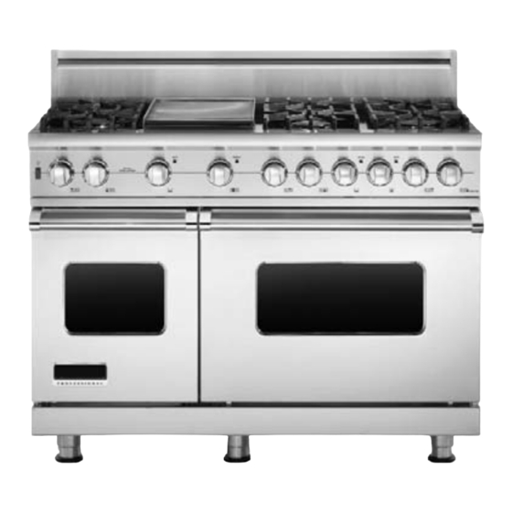
- Page 1 Installation Professional Freestanding Dual Fuel Ranges VDSC530 / VDSC536 / VDSC548 / VDSC560 CVDSC530 / CVDSC536 / CVDSC54 8...
-
Page 2: Table Of Contents
Table of Contents Warnings & Important Safety Instructions_ _ _ _ _ _ _ _ _ _ _ _ _ _ _ _ _ _ _ _ _ _ _ _ _ _ _ _ _ _ _ _ _ _ _ _ _ _ _ _ _ _ _ _ _ _ _ _ _ _ _ _ _ 3 Dimensions _ _ _ _ _ _ _ _ _ _ _ _ _ _ _ _ _ _ _ _ _ _ _ _ _ _ _ _ _ _ _ _ _ _ _ _ _ _ _ _ _ _ _ _ _ _ _ _ _ _ _ _ _ _ _ _ _ _ _ _ _ _ _ _ _ _ _ _ _ _ _ _ _ _ _ _ _ _ _ _ _ _ 6 Specifications _ _ _ _ _ _ _ _ _ _ _ _ _ _ _ _ _ _ _ _ _ _ _ _ _ _ _ _ _ _ _ _ _ _ _ _ _ _ _ _ _ _ _ _ _ _ _ _ _ _ _ _ _ _ _ _ _ _ _ _ _ _ _ _ _ _ _ _ _ _ _ _ _ _ _ _ _ _ _ _ 8 Clearance Dimensions (Proximity to Cabinets) _ _ _ _ _ _ _ _ _ _ _ _ _ _ _ _ _ _ _ _ _ _ _ _ _ _ _ _ _ _ _ _ _ _ _ _ _ _ _ _ _ _ _ _ _ _ _ 10... -
Page 3: Warnings & Important Safety Instructions
IMPORTANT– Read and Follow! • Before beginning, please read these instructions completely and carefully. Your safety and the safety of others is very important. • DO NOT remove permanently affixed We have provided many important safety labels, warnings, or plates from product. messages in this manual and on your This may void the warranty. - Page 4 IMPORTANT– Read and Follow! DANGER DANGER Chemical hazard. Fire/explosion hazard. IF THE INFORMATION IN To avoid risk of property damage and/or personal injury THIS MANUAL IS NOT FOLLOWED EXACTLY, A or death; this appliance is not too be used as a heating source. FIRE OR EXPLOSION MAY RESULT •...
- Page 5 DANGER WARNING Gas leak hazard. Moving hazard. To avoid risk of personal injury To avoid risk of severe personal injury; this appliance or death; leak testing of the appliance must be conducted requires two or more personnel according to the manufacturer’s while handling and moving.
-
Page 6: Dimensions
Dimensions Dual Fuel 30”, 36”, 48” and 60” W. Ranges - 7 / ( 9 1 8 ” - 7 / 8 ” ( 7 5 1 ” ( 2 . ( 9 1 - 7 / 8 ” n . ) ( 9 4 ”... - Page 7 Dimensions Dual Fuel 30”, 36”, 48” and 60” W. Ranges 28-1/16” (71.2 cm) 1-5/8” (4.1 cm) 26-7/16” (67.2 cm) 1” (2.5 cm) 8-1/8” (20.6 cm) 35-7/8” (91 cm min.) 37” (94 cm max.) 24-5/16” (61.8 cm) 19-3/8” 25-3/4” (49.2 cm) (65.4 cm) 45-1/8”...
-
Page 8: Specifications
Specifications Dual Fuel 30” and 36” W. Ranges Description 30” W. Models 36” W. Models Overall width 29-7/8” 35-7/8” (75.9 cm) (91.1 cm) Overall height To top of side trim - 35-7/8” (91.1 cm) min. 37” (94.0 cm) max. Legs adjust - 1-1/8” (2.9 cm) Overall depth To end of side panel - 24-5/16”... - Page 9 Specifications Dual Fuel 48” and 60” W. Ranges Description 48” W. Models 60” W. Models Overall width 47-7/8” 60” (121.6 cm) (152.4 cm) Overall height To top of side trim - 35-7/8” (91.1 cm) min. 37” (94.0 cm) max. Legs adjust - 1-1/8” (2.9 cm) Overall depth To end of side panel - 24-5/16”...
-
Page 10: Clearance Dimensions (Proximity To Cabinets)
Clearance Dimensions (Proximity to Cabinets) • This range may be installed directly CAUTION adjacent to existing 36” (91.4 cm) high base cabinets. To prevent possible damage to cabinets and cabinet finishes, use only materials IMPORTANT: The side trim MUST be and finishes that will not discolor or 3/8”... -
Page 11: Clearance Dimensions (Wood/Composite Overlay)
Clearance Dimensions (Wood/Composite Overlay) The bottom of a standard hood should be 30” (76.2 cm) min. to / C o 36” (91.4 cm) max. above the o s i e r l countertop. This would typically result in the bottom of the hood being 66”... -
Page 12: Electrical & Gas Requirements
The range is designed specifically for natural or moisture. gas or liquid propane (LP) gas. Before • Viking Range, LLC will NOT warranty any beginning installation verify that the model is problems resulting from GFI outlets which compatible with the intended are not installed properly or do not meet gas supply. - Page 13 Electrical & Gas Requirements Manual shut-off valve: Incoming line pressure upstream from the regulator must be 1” W.C.P. higher than The installer-supplied valve must be installed the manifold pressure in order to check in the gas service line before the appliance the regulator.
-
Page 14: General Information
General Information READ AND FOLLOW ALL WARNING Moving, Handling, and Unpacking AND CAUTION INFORMATION Remove and discard all packing materials, WHEN INSTALLING THIS APPLIANCE. including cardboard and tape on the outside and inside of the range. • All openings in the wall behind the appliance and in the floor under the Remove the burner grates and styrofoam appliance must be sealed. -
Page 15: Installation
Installation NOTICE DO NOT use the handle or oven door to lift the oven. Remove door before installation to ensure that it is not used to lift the unit. DO NOT lift or carry the door by the handle. Removing the door must be done by your dealer, a qualified licensed plumber, or certified gas installer. -
Page 16: Leg Installation
Leg Installation Legs are packed in styrofoam top pack. Note: It is strongly recommended Note: Legs should be installed near to where that a pallet or lift jack be used rather than tilting. appliance is to be used, as they are Raise unit about a foot. -
Page 17: Electrical Connection (3 Wire)
Electrical Connection (3-wire) Note: If you have a 4-wire connection, see following section for 4-wire connection instructions. WARNING WARNING Electrical shock hazard. Electrical shock hazard. To avoid risk or electrical To avoid risk of electrical shock, shock, personal injury or death; personal injury or death;... - Page 18 Electrical Connection (3-wire) (cont.) Push supply cord toward terminal Attach line #1 (red) and line #2 (black) leads to outside terminal. Attach neutral wire (white) block to relieve strain, reattach supply cord strain relief bracket over supply cord. to center terminal on the terminal block. Reattach access door.
-
Page 19: Electrical Connection (4 Wire)
Electrical Connection (4-wire) Remove access door. Remove supply cord strain relief bracket and three supply cord mounting screws on the terminal block. Remove grounding screw. Cut-off Feed supply cord up through hole in bottom and discard ground strap. of range back. Attach ground lead (green) Attach line #1 (red) and line #2 (black) with ground screw that was removed. -
Page 20: Leveling/Adjustments/Alignment
Electrical Connection (4-wire) (cont.) Reattach access door. Push supply cord toward terminal block to relieve strain, reattach supply cord strain relief bracket over supply cord. Leveling/Adjustments/Alignment Measure the four corners in cutout area to verify if For uneven or sloped floors, level unit with metal shims flooring is level. - Page 21 Leveling/Adjustments/Alignment If leveling is required, move unit out of opening. Lift unit and prop on wood blocks. Set the high corner of range so that the top of side trim is 3/8” (0.95 cm) above countertop. Level range to high corner.
-
Page 22: Anit-Tip Device Installation
Anti-tip Device Installation (Wall Mount) WARNING Tipping hazard. To reduce the risk of property damage or personal injury; install anti-tipping device provided in accordance with the installation instructions in this document. Device must be engaged properly to prevent product from tipping over. -
Page 23: Connecting Gas & Electrical
Anti-tip Device Installation (Floor Mount) 8 - 1 8 - 1 8 - 1 ( 2 1 ( 2 1 ( 2 1 ” ” ” Ø Ø Ø 8 ” 8 ” 8 ” ( . 3 ( . 3 ( . -
Page 24: Standoff Bracket Removal
Standoff Bracket Removal (48” and 60”W. VDSC Models Only) Note: Standoff brackets can only be removed if range is installed against a NON-COMBUSTIBLE wall. DANGER FIRE HAZARD Standoff brackets provide a 3/4” barrier between back of range and rear wall. These must be in place for adequate ventilation. -
Page 25: Door Replacement And Adjustment
Door Replacement and Adjustment Reattach door to range. Open door completely. Reattach hinge trim. Remove pins from holes in hinges. Close door. If the door needs to be adjusted, loosen hinge trim screws located in step 2. Adjust the screws located between the door and kickplate using a 5/32”... -
Page 26: Final Preparation
Final Preparation • All stainless steel body parts should be to remove encrusted materials, soak with wiped with hot, soapy water and with a hot, wet cloths to loosen the material, then liquid cleaner designed for this material. use a wool or nylon scraper. DO NOT use If buildup occurs, DO NOT use steel wool, a metal knife, spatula, or any other abrasive cloths, cleansers, or powders! -
Page 27: Service & Registration
Only authorized replacement parts may be used in performing service on the appliance. All servicing should be referred to a qualified technician. Contact Viking Range, LLC, 1-888-845-4641, for the nearest service parts distributor in your area or write to: VIKING RANGE, LLC... - Page 28 Viking Range, LLC 111 Front Street Greenwood, Mississippi 38930 USA (662) 455-1200 For product information, call 1-888-845-4641 or visit our web site at vikingrange.com in the US or brigade.ca in Canada F20533J EN (031516)
Need help?
Do you have a question about the 5 SERIES and is the answer not in the manual?
Questions and answers