Table of Contents
Advertisement
Quick Links
Advertisement
Table of Contents

Related Manuals for AIC FB127-AG


Summary of Contents for AIC FB127-AG
- Page 1 FB127-AG Storage Barebone User's Manual UM_FB127-AG_v1_041219...
-
Page 2: Table Of Contents
Table of Contents Preface ������������������������������������������������������������������������������������������������� i Safety Instructions ������������������������������������������������������������������������������ ii About This Manual ������������������������������������������������������������������������������ iv Chapter 1� Product Features �������������������������������������������������������������� 1 1.1 Box Contents ................... 1 1.2 Specifications ..................2 1.3 Feature ..................... 3 Chapter 2� Hardware Setup ���������������������������������������������������������������� 6 2.1 Central Processing Unit Setup ............... - Page 3 3.5 System LED Indicator ................27 3.5.1 Rear Panel LED ....................27 3.5.2 Internal LED ..................... 27 3.5.3 Internal LED Indicator Location ..............28 3.6 SSD Backplane ..................29 3.6.1 Placement ......................29 3.6.2 Connector and Switch ..................30 3.6.3 LED ........................33 Chapter 4.
- Page 4 4.6.3 TPM Availability ....................48 4.6.4 TPM Operation ....................48 4.7 Power......................49 4.7.1 Auto Wake on S5 ....................49 4.8 Boot ......................50 4.9 Exit ......................51 Chapter 5. BMC Configuration Settings �������������������������������������������� 52 5.1 Login .......................52 5.2 Web GUI ....................53 5.2.1 Menu Bar ......................53 5.2.2 User Information and Quick Button ...............
- Page 5 Document Release History Release Date Version Update Content April User's Manual release to public. 2019...
- Page 6 Copyright © 2019 AIC, Inc� All Rights Reserved� This document contains proprietary information about AIC products and is not to be disclosed or used except in accordance with applicable agreements.
-
Page 7: Preface
Disclaimer AIC shall not be liable for technical or editorial errors or omissions contained herein. The information provided is provided "as is" without warranty of any kind. To the extent permitted by law, neither AIC or its affiliates, subcontractors or suppliers will be liable for incidental, special or consequential damages including downtime cost;... -
Page 8: Safety Instructions
Safety Instructions Before getting started, please read the following important cautions: • All cautions and warnings on the equipment or in the manuals should be noted. • Most electronic components are sensitive to electrical static discharge. Therefore, be sure to ground yourself at all times when installing the internal components. •... - Page 9 • If one of the following situations arise, the equipment should be checked by service personnel: 1. The power cord or plug is damaged. 2. Liquid has penetrated the equipment. 3. The equipment has been exposed to moisture. 4. The equipment does not work well or will not work according to its user manual. 5.
-
Page 10: About This Manual
This document pellucidly presents a brief overview of the product design, device installation, and firmware settings for FB127-AG. For the latest version of this user's manual, please refer to the AIC website. Chapter 1 Product Features... -
Page 11: Chapter 1� Product Features
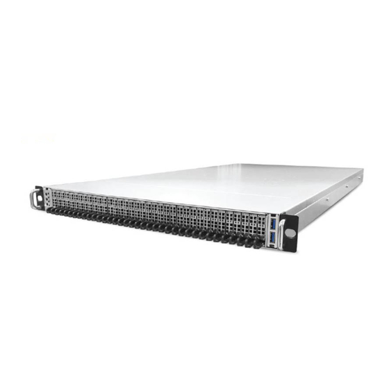
Chapter 1. Product Features FB127-AG User Manual Chapter 1. Product Features FB127-AG is a high density storage server that includes motherboard, chassis, power supply, and SSD backplane. For more information about our product, please visit our website at http://www.aicipc.com/en. Before removing the subsystem from the shipping carton, visually inspect the physical condition of the shipping carton. -
Page 12: 1.2 Specifications
Dimensions (W x D x H) inches : 17.2 x 31.5 x 1.7 • ACPI • PXE 2 x AIC Server Board Auriga Motherboard • WOL • AC loss recovery • Single AMD EPYC™ 7000-series • IPMI 2.0 KCS interface... -
Page 13: Feature
Chapter 1. Product Features 1�3 Feature FB127-AG is a reliable 1U storage server barebone with 36 hotswap drives bays. This product is designed to accommodate the AIC patented serverboard, Auriga, which sup- ports one AMD EPYC™ 7000-series processor and 8 DDR4 2400/2666 DIMM to offer greater perfomance, efficiency, and utility for our customers.Featuring the AMD EPYC™... - Page 14 FB127-AG User Manual Chapter 1. Product Features Front Panel USB3.0 Type A port Power On/Off Button links to motherboard (Right) USB3.0 Type A port System ID1 Button links to motherboard (Left) System ID2 Button Power Status LED Drive Activity LED...
- Page 15 FB127-AG User Manual Chapter 1. Product Features Top View 1300W 1+1 redundant power supply 80+ Platinum 6x40x56mm easy swap fans...
-
Page 16: Chapter 2� Hardware Setup
Chapter 2� Hardware Setup Chapter 2. Hardware Setup FB127-AG User Manual This section describes a simple instruction guide for installing the hardware components on the serverboard system. Turn off and unplug all system and peripheral devices before proceeding. 2�1 Central Processing Unit Setup The serverboard supports a single AMD EPYC™... - Page 17 FB127-AG User Manual Chapter 2. Hardware Setup Lift the carrier frame by the blue metal tab and remove the protective cover as demonstrated in figure 3 and figure 4. Lift carrier frame Remove protective cover Front Front Insert the CPU package into the carrier frame as demonstrated in figure 5.
- Page 18 Chapter 2. Hardware Setup FB127-AG User Manual Close the carrier frame with the CPU package as demonstated in figure 7. Check if the frame is properly installed as demonstrated in figure 8. Close carrier frame Verify installation Front Front ...
-
Page 19: System Memory Setup
FB127-AG User Manual Chapter 2. Hardware Setup 2�2 System Memory Setup This server board supports 8 memory slots. 2�2�1 DIMM Installation Unlock the DIMM socket by pressing the retaining clips outward. Insert the memory module into the slot. Make sure that the DIMM notch is accurately ... -
Page 20: Dimm Location
Chapter 2. Hardware Setup FB127-AG User Manual 2�2�2 DIMM Location The DIMMs are displayed on the Aurigaboard as JDMA0, JDMB0, JDMC0, JDMD0, JDME0, JDMF0, JDMG0, JDMH0 as demonstrated. JDMA0 and JDME0 are the located nearest to the CPU. To ensure satisfactory performance, you need to: ... -
Page 21: Top Cover
FB127-AG User Manual Chapter 2. Hardware Setup 2�3 Top Cover 2�3�1 Removing the Top Cover Push the cover toward the rear panel. Lift the top cover upward to remove. ... -
Page 22: Power Supply Unit Module
Chapter 2. Hardware Setup FB127-AG User Manual 2�4 Power Supply Unit Module 2�4�1 Replacing the Power Supply Unit Press the latch to release the module. Pull the handle to remove the module out of the chassis. Push the replaced power supply unit into the chassis. Ensure that the module ... -
Page 23: Fan Module
FB127-AG User Manual Chapter 2. Hardware Setup 2�5 Fan Module 2�5�1 Replacing the Fan Remove the node from the chassis. Please refer to Section 2.4. Unplug the cables and connectors. Pull the fan module from the node. Check to carefully dislodge the rubber ... -
Page 24: Nvme Ssd
Chapter 2. Hardware Setup FB127-AG User Manual 2�6 M�2 NVMe SSD 2�6�1 Replacing the Solid State Drive Press the release button the tray lever to loosen the lever. Pull the tray lever outward completely. Pull the tray out of the system. -
Page 25: Sdd Backplane
FB127-AG User Manual Chapter 2. Hardware Setup 2�7 SDD Backplane 2�7�1 Replacing the Backplane Detach the cables and hard disk drives from the backplane module. Release the module by shifting the hook. Dislodge the screws on the module. -
Page 26: Riser Card
Chapter 2. Hardware Setup FB127-AG User Manual 2�8 Riser Card 2�8�1 Replacing the Riser Card Loosen the captive screw on the riser card braket. Pull upward to remove the riser card cage from the system. Dislodge the screws on the cage to remove bracket holding the riser card. -
Page 27: Slide Blade Installation
FB127-AG User Manual Chapter 2. Hardware Setup 2�9 Slide Blade Installation Pull on the ‘’Front-Release’’to unlock the inner channel from the Slide Assembly. Release the Detent-Lock and push Middle Channel inwards to retract Middle Channel. - Page 28 Chapter 2. Hardware Setup FB127-AG User Manual Optional: Remove Metal Spacer for Aluminium Racks Metal Spacer Aligning the Front Bracket with the Mounting Hole. Push in to assembly the Front Bracket onto the Rack. ...
- Page 29 FB127-AG User Manual Chapter 2. Hardware Setup Now the bracket is fixed onto the Rack. (Optional M6x10L screws are to secure the rails with posts if needed.) Refer to step 3 and 4 to assemble the End Bracket onto the Rack.
- Page 30 Chapter 2. Hardware Setup FB127-AG User Manual Assemble the inner channel onto the chassis using thescrews provided. Push the chassis with inner channels into Slide to complete Rack Installation. ...
-
Page 31: Chapter 3� Hardware Settings
Chapter 3� Hardware Settings FB127-AG User Manual Chapter 3. Hardware Settings This section provides illustrations that display the internal jumpers, connectors, and system LED indicators on the Auriga motherboard. The motherboard layout and essential connectors are listed below for your reference. -
Page 32: Content List
FB127-AG User Manual Chapter 3. Hardware Settings 3�2 Content List Connector/Jumper/Header Location Connector/Jumper/Header Location JG0FR1 JG0FR2 JG1FR1 JG1FR2 PCIe Bus SAS slimline Battery Socket JBAT1 Connector (For CR2032) JG2FL1 JG2FL2 JG3FL1 JG3FL2 JFAN1 JFAN2 Fan Header 22 SOC CMOS Clear Header JCMOS1... -
Page 33: Connector And Jumper Location
FB127-AG User Manual Chapter 3. Hardware Settings 3�3 Connector and Jumper Location CPU0 A2 A1 K A2 A1 K... -
Page 34: Connector And Jumper
FB127-AG User Manual Chapter 3. Hardware Settings 3�4 Connector and Jumper 2 a Fan Header (JFAN1) 6 Power Supply Connector (JPWR1) FANTACH_2 1 2 FANTACH_1 +12V_S0 1 GND +12V_S0 2 GND +12V_S0 3 4 +12V_S0 +12V_S0 3 GND SYS1_FAN_PWM_C 5 6 SYS1_FAN_PWM_C... - Page 35 FB127-AG User Manual Chapter 3. Hardware Settings 17 Front I/O USB Header (JUSB_INT1) 34 Chassis Intrusion Header (JINTRUDER1) +5V_HUB2 2 +5V_HUB2 1 CHASSIS_OPEN_N USB2_HUB1_DN 4 USB2_HUB2_DN 2 GND USB2_HUB1_DP 6 USB2_HUB2_DP 35 BMC Buzzer Header (JBUZZER1) 8 GND KEY (no pin)
- Page 36 FB127-AG User Manual Chapter 3. Hardware Settings 40 Front panel Header for RACK (JRACK1) RACK_EXTRST_N 2 BMC_I2C_08_SCL 4 BMC_I2C_08_SDA BMC_I2C_01_SCL 6 GND BMC_I2C_01_SDA 8 RACK_PWM0 10 RACK_TACH0 RACK_PMBUS _CLK 11 12 GND RACK_PMBUS _DATA 13 14 RACK_PWM1 PMBUS_ALERT_N 15 16 RACK_TACH1...
-
Page 37: System Led Indicator
FB127-AG User Manual Chapter 3. Hardware Settings 3�5 System LED Indicator 3�5�1 Rear Panel LED Cable Link/Active Status: 1. Cable Plug-In : Green Green LAN1 (Right, JLAN1 Pin-13,14) 2. Cable Plug-Out : Off 1. 1Gbps : Green Linking Speed: Green 2. -
Page 38: Internal Led Indicator Location
FB127-AG User Manual Chapter 3. Hardware Settings 3�5�3 Internal LED Indicator Location... -
Page 39: Ssd Backplane
FB127-AG User Manual Chapter 3. Hardware Settings 3�6 SSD Backplane 3�6�1 Placement Top view JPMBUS1 JPICE32_USB JPIC32_ICE JPMBUS SW1 SW2 JPWR1 JPWR2 JPWR_MB1 J1 J2 J3 JPWR_MB2 Thermal sensor J6 J7 JMB_ID_A JMB_ID_B J1 K1 J2 K2 JFRONT Bottom view... -
Page 40: Connector And Switch
FB127-AG User Manual Chapter 3. Hardware Settings 3�6�2 Connector and Switch Power Output Connector for Node Motherboard (JPWR_MB1, JPWR_MB2 ) Description Description 7 PWRON_MB1/2 14 PWROK_MB1/2 6 GND 13 +5VSTBY_MB1/2 5 GND 12 +12V 4 GND 11 +12V 3 GND... - Page 41 FB127-AG User Manual Chapter 3. Hardware Settings FAN Connector (J1, J2, J3) Description Description 2 FAN_TACH_1 FAN_TACH_2 4 +12V +12V 6 PWM_1 PWM_1 8 GND FAN Connector (J4, J5, J6, J7) Description Description 2 FAN_TACH_1 FAN_TACH_2 4 +12V +12V 6 PWM_2...
- Page 42 FB127-AG User Manual Chapter 3. Hardware Settings Bootloader mode switch (SW1) Boot loader SW Default High (Active low) MCU PIC32 Reset (SW2) MCLR Default High (Active low)
-
Page 43: Led
FB127-AG User Manual Chapter 3. Hardware Settings 3�6�3 LED Top view LED1 LED2, LED3, LED4, LED5 Bottom view LED2000-LED2035 Drive status normal. No HDD activity. Green Blinking Drive activity (4Hz). NF1/M.3 SSD Link/Fail Drive is not present. Activity LEDs (LED2000-LED2035) Drive fault status. -
Page 44: Chapter 4. Bios Configuration Settings
Chapter 4. BIOS Configuration Settings FB127-AG User Manual Chapter 4. BIOS Configuration Settings This chapter demonstrates how to configure the UEFI BIOS settings in your system device. You can enter the BIOS screen during system startup. To enter BIOS configuration settings, •... -
Page 45: Bios Setup
FB127-AG User Manual Chapter 4. BIOS Configuration Settings 4�2 BIOS Setup 4�2�1 BIOS Menu Press and to select the options of the menu bar. Press Enter to access the option screen. Menu Description Main Displays system information such as CPU bus speed, system memory speed, total installed memory, current EFI language, and system date &... - Page 46 FB127-AG User Manual Chapter 4. BIOS Configuration Settings There will be a message “Entering SETUP” displayed on the diagnostics screen. Identify the BIOS version. ...
- Page 47 FB127-AG User Manual Chapter 4. BIOS Configuration Settings Load Optimal Default Setting. Save the setting and exit the BIOS setup utility. ...
-
Page 48: Main
FB127-AG User Manual Chapter 4. BIOS Configuration Settings 4�3 Main 4�3�1 Main Main Option Key: Option Key Description Language Configures the language used for your BIOS settings. System time Configures the current time. System date Configures the current date. -
Page 49: Amd Cbs
FB127-AG User Manual Chapter 4. BIOS Configuration Settings 4�4 AMD CBS AMD CBS Option Key: 4�4�1 Zen Common Options Zen Common Options Core Performance Auto Disable Boost Global C-state Auto Enable Disable Control Global C-state Min=0x1, Max=0x10 Control Custom Core... -
Page 50: Df Common Options
FB127-AG User Manual Chapter 4. BIOS Configuration Settings 4�4�2 DF Common Options DF Common Options Memory None Channel Socket Auto interleaving Memory Auto interleaving ACPI SRAT below 1MB Auto Report as DRAM Do not report reporting mode 4�4�3 UMC Common Options... - Page 51 FB127-AG User Manual Chapter 4. BIOS Configuration Settings Activate Delay TrrdL Time, same bank group Auto Tfaw Ctrl Manual Min=0x6 Tfaw Max=0x36 Minimum Write to Read Time, TwtrS different bank group Minimum Write to TwtrL Read Time, same bank group...
- Page 52 FB127-AG User Manual Chapter 4. BIOS Configuration Settings Trdwr tWRTTO time. Read delay Twrrd when accessing different DIMMs. TwrwrSc TwrwrSd Write to iwrite TwrwrDd timing same DRAM Timing I Accept TrdrdSc DIMM same chip Configuration TrdrdSd select. TrdrdDd CKE minimum...
-
Page 53: Nbio Common Options
FB127-AG User Manual Chapter 4. BIOS Configuration Settings 4�4�4 NBIO Common Options NBIO Common Options Determinism Slider Auto Power Performance cTDP Control Auto Manual Block PCIe Auto Enable Disable Loopback CRS Delay Min=0x0, Max=0xffff CRS Limit Min=0x0, Max=0xffff Auto IOMMU... -
Page 54: Advanced
FB127-AG User Manual Chapter 4. BIOS Configuration Settings 4�5 Advanced Advanced Option Key: 4�5�1 Demo Board Demo Board OnBrd/Ext VGA Select Auto Onboard External 4�5�2 USB Configuration USB Configuration USB Hardware SMI Enable Disable support USB Ports Per-Port Enable Disable Disable Control USB 3.0 Port 0... -
Page 55: Cpu Related Setting
FB127-AG User Manual Chapter 4. BIOS Configuration Settings 4�5�3 CPU Related Setting CPU Related Setting SVM support Enable Disable SMM Code Lock Enable Disable AMD CPU P-state Control Enable Disable 4�5�4 PCI Sub System Setting PCI Sub System Setting Above 4G resource decoding... -
Page 56: H2O Event Log Config Manager
FB127-AG User Manual Chapter 4. BIOS Configuration Settings Power Cycle Time Enable Disable Support Power Cycle Time Min=0, Max=255 Power Button Enable Disable Reset Button Enable Disable NMI Button Enable Disable BMC Configuration Lan Port Dedicated Shared Configuration Lan Port... -
Page 57: Console Redirection
FB127-AG User Manual Chapter 4. BIOS Configuration Settings Serial Debug Show Debug Configuration Pages Message Code Serial Enable Disable Configuration Message Event And Message Read only. Pages 4�5�9 Console Redirection Console Redirection Console Serial Enable Disable Redirect Terminal Type VT_100... -
Page 58: Security
FB127-AG User Manual Chapter 4. BIOS Configuration Settings 4�6 Security Security Option Key: 4�6�1 Current TPM Device Current TPM Device Not detected TPM 2.0 4�6�2 TrEE Protocol Version TrEE Protocol Version 4�6�3 TPM Availability TPM Availability Available Hidden 4�6�4 TPM Operation... -
Page 59: Power
FB127-AG User Manual Chapter 4. BIOS Configuration Settings 4�7 Power Disabled,By Every Day,By Day of Mo nth Power Option Key: 4�7�1 Auto Wake on S5 Auto Wake on S5 Disable By Every Day By Day of Month... -
Page 60: Boot
FB127-AG User Manual Chapter 4. BIOS Configuration Settings 4�8 Boot Boot Option Key: Boot Boot Type UEFI Boot Type Legacy Boot Type Quick Boot Enable Disable Quiet boot Enable Disable Network Stack Enable Disable PXE Boot capability Enable Disable Power Up in Standby Support... -
Page 61: Exit
FB127-AG User Manual Chapter 4. BIOS Configuration Settings 4�9 Exit Exit Option Key: Save and Exit Exit Saving Changes Exit system setup and save your changes. Save Change Without Exit Save your changes without exiting the system. Exit Discarding Changes Discard your changes when existing the system. -
Page 62: Chapter 5. Bmc Configuration Settings
Chapter 5. BMC Configuration Settings FB127-AG User Manual Chapter 5. BMC Configuration Settings This chapter displays the configuration settings of IPMI BMC in your system device. 5�1 Login NOTE This feature works with the html5. Please use a browser that supports html5. -
Page 63: Web Gui
FB127-AG User Manual Chapter 5. BMC Configuration Settings 5�2 Web GUI 5�2�1 Menu Bar Click to select the options of the menu bar. Menu Description The Dashboard page gives the overall information about the status Dashboard of a device. The Sensor Readings page displays all the sensor related Sensor information. -
Page 64: User Information And Quick Button
FB127-AG User Manual Chapter 5. BMC Configuration Settings 5�2�2 User Information and Quick Button The user information and quick access buttons are located at the top right corner. It displays the logged-in user, his/her privilege and the four quick buttons allowing you to perform different functions. -
Page 65: Dashboard
FB127-AG User Manual Chapter 5. BMC Configuration Settings 5�2�3 Dashboard The Dashboard page displays device, system information, and assert logs. Click Dashboard on the menu bar to view the overall information of the server. 5�2�4 Sensor The Sensor page displays the status and records on related sensors. Click a record to... -
Page 66: Fru Information
FB127-AG User Manual Chapter 5. BMC Configuration Settings 5�2�5 FRU Information The FRU Information page displays Basic Information, Chassis Information, Board Information and Product Information of the FRU device. Click FRU Information on the menu bar to view the details of the selected device. -
Page 67: Logs And Report
FB127-AG User Manual Chapter 5. BMC Configuration Settings 5�2�6 Logs and Report The System Inventory page displays IPMI Event Log and Video Log. Click Logs and Reports from the menu bar and select Event Log or Video Log to view the contents. -
Page 68: Settings
FB127-AG User Manual Chapter 5. BMC Configuration Settings 5�2�7 Settings The Settings page displays the configuration settings for Date & Time, External User Services, KVM Mouse Setting, Log Settings, Media Redirection Settings, Network Settings, PAM Order Settings, Platform Event Filter, Services, SMTP Settings, SSL... - Page 69 FB127-AG User Manual Chapter 5. BMC Configuration Settings Settings Menu and Option Key: Settings Description Date and Time LDAP/E-directory Active directory Settings Radius Settings Settings External User General Advanced Services General Role General Role Radius Radius Settings Groups Settings Groups...
-
Page 70: Remote Control
FB127-AG User Manual Chapter 5. BMC Configuration Settings 5�2�8 Remote Control The Remote Control page displays the configuration for power control and remote KVM. Click Java Console to start the JViewer video redirection. - Page 71 FB127-AG User Manual Chapter 5. BMC Configuration Settings Click Launch KVM to open the Remote KVM page.
- Page 72 FB127-AG User Manual Chapter 5. BMC Configuration Settings Procedure to Start KVM Step 1 Click Start KVM to start the H5Viewer video redirection. Step 2 Click Browse to select CD Image. Step 3 Click Start Media to redirect the selected CD image file to the Host.
- Page 73 FB127-AG User Manual Chapter 5. BMC Configuration Settings Remote KVM Menu and Option Key: Remote KVM Description Start KVM Starts the H5Viewer video redirection. Stop KVM Stops the H5Viewer video redirection. Pause Video This option is used for pausing Console Redirection.
- Page 74 FB127-AG User Manual Chapter 5. BMC Configuration Settings This menu item can be used to act Right <Ctrl> as the right-side <CTRL> key during Console Redirection. This menu item can be used to act Right <Alt> as the right-side <ALT> key during Console Redirection.
-
Page 75: Power Control
FB127-AG User Manual Chapter 5. BMC Configuration Settings 5�2�9 Power Control The Power Control page allows you to view and control the power of your server. To open Power Control, click Power Control from the menu bar. The various options of Power Control are given below. -
Page 76: Chassis Identify Control
FB127-AG User Manual Chapter 5. BMC Configuration Settings 5�2�10 Chassis Identify Control The Chassis Identify Control page displays the BMC’s UID control information. Users can change the Identify LED behavior on this page. Click Chassis Identify Control from the menu bar. Select Off/On to control UID LED. - Page 77 FB127-AG User Manual Chapter 5. BMC Configuration Settings Maintenance Description 1. Click Check All to backup the selected configuration items. The Backup Configuration page will appear Click Download Config to save the backup Backup file to the client system. Configuration 2.
-
Page 78: Sign Out
FB127-AG User Manual Chapter 5. BMC Configuration Settings 5�2�12 Sign out To log out of the BMC: Method 1: Click Sign out from the menu bar. The Logout dialog box will pop out. Cancel Method 2: Click the root quick button on the top right corner of the screen. -
Page 79: Chapter 6� Technical Support
Chapter 6� Technical Support FB127-AG User Manual Chapter 5. BMC Configuration Settings Taiwain, Global Headquarters South California, United States Address: No� 152, Section 4, Address: 21808 Garcia Lane Linghang N� Rd, Dayuan District, City of Industry, CA 91789, Taoyuan City 337, Taiwan...
Need help?
Do you have a question about the FB127-AG and is the answer not in the manual?
Questions and answers