Table of Contents
Advertisement
Quick Links
Advertisement
Table of Contents

Related Manuals for AIC HA201-AP


Summary of Contents for AIC HA201-AP
- Page 1 HA201-AP Storage Server Barebone User's Manual UM_HA201-AP_v.1_032717...
-
Page 2: Table Of Contents
CONTENTS PREFACE ������������������������������������������������������������������������������������������������������ i SAFETY INSTRUCTIONS ������������������������������������������������������������������������������� ii Chapter 1� Product Introduction ����������������������������������������������������������������������������� 1 1�1 Box Content ������������������������������������������������������������������������������������������������������ 1 1.2 Specifications ��������������������������������������������������������������������������������������������������� 2 1�3 General Information ����������������������������������������������������������������������������������������� 3 Chapter 2� Hardware Installation ����������������������������������������������������������������������������� 7 2�1 Removing and Installing top cover ���������������������������������������������������������������� 7 2�2 System Memory ������������������������������������������������������������������������������������������������... - Page 3 5�1 Backplane ������������������������������������������������������������������������������������������������������� 53 Chapter 6� Technical Support �������������������������������������������������������������������������������� 57 contents...
- Page 4 Copyright © 2017 AIC, Inc� All Rights Reserved� This document contains proprietary information about AIC products and is not to be disclosed or used except in accordance with applicable agreements.
-
Page 5: Preface
AIC shall not be liable for technical or editorial errors or omissions contained herein. The information provided is provided "as is" without warranty of any kind. To the extent permitted by law, neither AIC or its affiliates, subcontractors or suppliers will be liable for incidental, special or consequential damages including downtime cost;... -
Page 6: Safety Instructions
SAFETY INSTRUCTIONS • Before getting started, please read the following important cautions: • All cautions and warnings on the equipment or in the manuals should be noted. • Most electronic components are sensitive to electrical static discharge. Therefore, be sure to ground yourself at all times when installing the internal components. - Page 7 • Place the power cord out of the way of foot traffic. Do not place anything over the power cord. The power cord must be rated for the product, voltage and current marked on the product’s electrical ratings label. The voltage and current rating of the cord should be greater than the voltage and current rating marked on the product.
-
Page 8: Chapter 1� Product Introduction
• Enclosure( Power supply, fan, 24 HDD tray included) • RS232 cablex 1pcs • Power cord x 2sets • Screws kit x 1set • Slide rail x 1set If any items are missing, please contact your authorized reseller or sales representative. HA201-AP User's Manual... -
Page 9: 1.2 Specifications
FLASH Interface (with chassis ears) inches : 24.9 x 17.1 x 3.5 • ACPI • PXE Motherboard AIC Server Board Apollo • WOL (per node) • AC loss recovery Processor One Intel® Xeon® Processor D-1500 product • IPMI 2.0 KCS interface... -
Page 10: 1�3 General Information
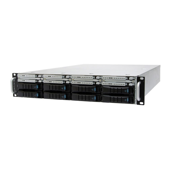
1�3 General Information HA201-AP, a 2U Storage Server Barebone, ach supporting one Intel® Xeon-D® Processor and up to 128GB of DDR4 memory. HA201-AP has a 8 x 2.5” hot swap HDD bays as system drive bays. It is a perfect building block for Storage Servers. - Page 11 Chapter 1 Product Introduction • Rear Panel Supports 1 x8 FHHL PCIe 3.0 slots (per node) Dual server board controller canisters 600W 1+1 redundant power supply HA201-AP User's Manual...
- Page 12 Chapter 1 Product Introduction • Top View of HA201-AP system Two compute nodes, Active-Active configuration, each supporting one Intel® Xeon-D® Processor and up to 128GB of DDR4 memory HA201-AP User's Manual...
- Page 13 Chapter 1 Product Introduction • TOP View Of Controller Canister Broadcom/LSI SAS3008 12G 8port SAS IOC Broadcom/LSI SAS3x36/3x28 12G SAS Expander BroadWell-DE SoC (Xeon D1500 series) HA201-AP User's Manual...
-
Page 14: Chapter 2� Hardware Installation
This section demonstrates maintenance procedures in replacing a defective part once the HA201-TP UM appliance is installed and is operational 2�1 Removing and Installing top cover There are four screws on the each upper surface of the cover. HA201-AP User's Manual... -
Page 15: 2�2 System Memory
SAS EXP HEART BIT LED JCOM1 PCIE HOT-PLUG SMB JSGPIO JBMC_GPIO JBMC_I2C1 LED7:RSMRST PG LED LED8:SYSTEM PG LED SATA5 SATA3 TP15 JEXP_RST SAS IOC ICE SAS IOC SGPIO SAS EXP SGPIO SATA6 SATA4 JBMC_RST JBMC_DP JNTB JUSB_MB JINTRUDER JLCM JFRNT_SSI HA201-AP User's Manual... -
Page 16: Chapter 2 Hardware Installation
2.2.1 Populate DIMMs in the following order: DIMM Number DIMM arrangement JDIMM_B1 1 DIMMs JDIMM_B1 JCPU0 JDIMM_A1 JDIMM_B1 2 DIMMs JDIMM_A1 JDIMM_B1 JCPU0 JDIMM_A1 JDIMM_B0 JDIMM_B1 JDIMM_A1 JDIMM_B1 3 DIMMs JDIMM_B0 JCPU0 JDIMM_A0 JDIMM_A1 JDIMM_B0 JDIMM_B1 4 DIMMs JDIMM_A1 JDIMM_B1 JDIMM_A0 JDIMM_B0 JCPU0 HA201-AP User's Manual... - Page 17 2.2.2 DIMM Installation Procedure Unlock a DIMM socket by pressing the retaining clips outward. Insert module vertically and press down until it snaps into place. Note: DIMM notch and socket bump must align as shown. DIMM notch HA201-AP User's Manual...
-
Page 18: 2�3 Removing And Installing The Canister Top Cover
2�3 Removing and Installing the canister Top cover 2.3.1 Removing the top cover 1. Unscrew the thumbscrew using your fingers or a Phillips head screwdriver. Be careful to retain the thumbscrew. 2. Carefully lift the top cover upward and set aside. HA201-AP User's Manual... -
Page 19: 2�4 Installing/ Removing A Solid State Drive
(Installing a total of 4 screws). See the characters 2. Place the SSD into its a bracket kit, line it up with the holes on either side,then screw it in (Installing a total of 8 screws for 2 x SSD’s). See the characters HA201-AP User's Manual... -
Page 20: 2�5 Removing And Installing A Fan Module
NOTE: The heat sink’s fans should be blowing toward the rear end of the chassis. If one of the fans is facing the wrong direction, please remove the heat sink and reinstall it so that it is facing the correct direction. HA201-AP User's Manual... -
Page 21: 2�6 Removing/Installing A Drive Tray/ Hard Drive/ Drive Slot Map
2�6 Removing/Installing a Drive Tray/ Hard Drive/ Drive Slot Map 2.6.1 Removing a Disk Drive Release a drive tray by pressing the unlock button and pinching the lock lever slightly and pulling out the drive tray. 2�5'' HDD 3�5''HDD HA201-AP User's Manual... - Page 22 Chapter 2 Hardware Installation 2.6.2 Installing a 3.5'' HDD Interposer Board Align the interposer module into the interposer brecket. Tighten the screws to secure the interposer board. HA201-AP User's Manual...
- Page 23 Chapter 2 Hardware Installation 2.6.3 Installing a 2.5'' HDD Interposer Board Gently push down on the interposer board to engage the connector on the board with the connector on the HDD tray. HA201-AP User's Manual...
- Page 24 Insert the drive carrier into its bay. Push the tray lever until it clicks. Make sure the drive tray is correctly secured in place when its front edge aligns with the bay edge. 2.6.4 Drive Slot Map The drive slot map follows. HBA Card MegaRaid Card HA201-AP User's Manual...
-
Page 25: 2�7 Removing And Installing The Hdd Backplane Module
• Grasp and lift up the blackplane then can get out. 2.7.2 Installing a HDD backplane module • Slide the HDD backplane module into enclosures. • Secure the HDD backplane module onto the enclosures using the screws. Follow the reverse order. HA201-AP User's Manual... -
Page 26: 2�8 Removing And Installing The Power Supply
2�8 Removing and Installing the Power Supply 2.8.1 Removing or Replacing the Power Supply Module Slide the small levers (see red arrow ) to the right. Hold the PSU lever and firmly pull the PSU out of the server chassis. HA201-AP User's Manual... -
Page 27: 2�9 Removing And Installing The Pcie Card
PCIe card into the riser card assembly. Pree the edge of the gold finger firmly into the riser card assembly. Make sure that the PCIe card is securely installed in the riser card assembly. HA201-AP User's Manual... - Page 28 Chapter 2 Hardware Installation 2. Tighten the previously removed screw to secure the card. HA201-AP User's Manual...
-
Page 29: 2�10 Tool-Less Blade Slide Installation Introduction
Chapter 2 Hardware Installation 2�10 Tool-less Blade Slide Installation introduction 1. Pull on the ‘’Front-Release’’to unlock the inner channel from the Slide Assembly. 2. Release the Detent-Lock and push Middle Channel inwards to retract Middle Channel. HA201-AP User's Manual... - Page 30 Chapter 2 Hardware Installation Optional: Remove Metal Spacer for Aluminium Racks Metal Spacer 3. Aligning the Front Bracket with the Mounting Hole. 4. Push in to assembly the Front Bracket onto the Rack. HA201-AP User's Manual...
- Page 31 Chapter 2 Hardware Installation 5. Now the bracket is fixed onto the Rack. (Optional M6x10L screws are to secure the rails with posts if needed.) 6. Refer to Diagram 3. & 4. to assemble the End Bracket onto the Rack. HA201-AP User's Manual...
- Page 32 Chapter 2 Hardware Installation 7. Assemble the inner channel onto the chassis using thescrews provided. 8. Push the chassis with inner channels into Slide to complete Rack Installation. HA201-AP User's Manual...
-
Page 33: Chapter 3� Motherboard Settings
Flash UART0 S25FL256SAGMFI001 Debug port @12Gb/s @12Gb/s ICE0 NVSRAM I210AT PCI Express x 1 Debug port CY14V101LA-BA25 Flash @5GT/s S29GL128S11TFIV2 SAS3X36 (SAS3X28) SFF-8644 SAS PHY x4 SAS PHY x20 SFF-8644 SAS PHY x4 SAS PHY x4 Option HA201-AP User's Manual... -
Page 34: 3�2 Motherboard Layout
LED7:RSMRST PG LED LED8:SYSTEM PG LED SATA5 SATA3 TP15 JEXP_RST SAS IOC ICE SAS IOC SGPIO SAS EXP SGPIO SATA6 SATA4 JBMC_RST JNTB JUSB_MB JBMC_DP JNTB JINTRUDER JLCM JFRNT_SSI JFRNT_SSI JUSB_MB JLCM JINTRUDER JBMC_GPIO JBMC_DP JSGPIO JBMC_I2C1 HA201-AP User's Manual... -
Page 35: 3�3 Motherboard Content List
SAS IOC ERROR System PG Lock JPG_LOCK 58 SAS IOC ACTIVITY BMC Buzzer JBUZZER BIOS Recovery SAS IOC ICE Mode ME Force SAS IOC SGPIO Recovery Mode Flash Descriptor SAS EXP SKU Security override Reboot(Watch SATA Power HA201-AP User's Manual Dog) -
Page 36: 3�4 Internal Connectors/Jumpers
78 76 74 72 70 68 74 74 72 70 68 68 R362 77 75 77 75 77 75 73 71 69 73 71 69 LED1 JBMC_I2C10 JBMC_DIS UID LED JCOM1 PCIE HOT-PLUG SMB JSGPIO JBMC_GPIO JBMC_I2C1 JBMC_RST JBMC_DP JLCM JINTRUDER JBMC_DP HA201-AP User's Manual... - Page 37 Internal Connectors/Jumpers JBMC_I2C10 JBUZZER JVGA_INT BMC BUZZER- DACROA I2C10SDA DACGOA I2C10SCL DDC_DATAO DACBOA AHSYNCO DVO_5V AVSYNCO DDC_CLKO JINTRUDER JLCM JBMC_DP JCOM1 JLCM JINTRUDER Setting ShortC ase Open OFFE nable( Default) JCOM1 JBMC_I2C10 JBMC_GPIO JCOM4 I2C10SDA I2C10SCL JSGPIO JDOM_PWR HA201-AP User's Manual...
- Page 38 Inlet Thermal Sensor JPG_LOCK JSPI_BIOS JPG_LOCK SAS EXP MDIO SAS EXP HEART BIT LED LED7:RSMRST PG LED LED8:SYSTEM PG LED SATA3 SATA5 TP15 JEXP_RST SAS IOC ICE SAS IOC SGPIO SAS EXP SGPIO SATA4 SATA6 JUSB_MB JFRNT_SSI JUSB_MB JFRNT_SSI HA201-AP User's Manual...
- Page 39 Chapter 3 Motherborad Overview Internal Connectors/Jumpers JPWR2 JPMBUS J8 J9 J10 +12V J14 J15 J16 JPWR2 JPWR1 JVBATT_12C JUSB_MB JUSB_MB JVBATT_I2C JFRNT_SSI JFRNT_SSI HA201-AP User's Manual...
- Page 40 7 7 5 BROADWELL-DE SAS EXP MDIO SAS EXP HEART BIT LED LED7:RSMRST PG LED LED8:SYSTEM PG LED SATA5 SATA3 TP15 JEXP_RST SAS IOC ICE SAS IOC SGPIO SAS EXP SGPIO SATA4 SATA6 JNTB JNTB JUSB_MB JFRNT_SSI HA201-AP User's Manual...
- Page 41 Chapter 3 Motherborad Overview Internal Connectors/Jumpers JSPKR JNGFF HA201-AP User's Manual...
- Page 42 Chapter 3 Motherborad Overview Internal Connectors/Jumpers JLPC_DP CLK_33M_DP80 PCH_LFRAME_N PCH_GPIO61 RST_PLTRST_N PCH_SERIRQ PCH_LPC_LAD3 PCH_LPC_LAD2 PCH_LPC_LAD1 +3.3V PCH_LPC_LAD0 HA201-AP User's Manual...
- Page 43 Chapter 3 Motherborad Overview Internal Connectors/Jumpers JPCH_GPIO JUSB_INT JSPI_BIOS JPCH_GPIO HOLD# +3.3V PCH_GPIO9 PCH_GPIO21 PCH_GPIO10 PCH_GPIO27 HA201-AP User's Manual...
-
Page 44: 3�5 Leds
No critical failures detected Green (Blinking) Disk activity detected Hard Disk No disk activity detected Green (Blinking) NIC1 activity detected NIC 1 NIC is not active Green (Blinking) NIC2 activity detected NIC 2 NIC is not active HA201-AP User's Manual... - Page 45 Status LED 1G : Orange, 100M: Green 10M/No NIC 4 (Left) connect: Off Yellow PHY 1 (Right) (Blinking) 100M: Yellow 10M/No connect: Off Green PHY1 activity detected PHY 1 (Left) PHY1 is not active, LAN cable no connect HA201-AP User's Manual...
- Page 46 Blue(Blinking) SAS EXP activity detected SAS EXP HEART BIT LED SAS EXP not activity detected Synchronize Multi-EXP Blue(Blinking) activity detected SAS EXP SYNC BLINK Synchronize Multi-EXP not activity detected Blue(Blinking) NGFF activity detected NGFF ACTIVITY LED NGFF not activity detected HA201-AP User's Manual...
-
Page 47: Chapter 4. Bios Configuration And Settings
Chapter 4. BIOS Configuration and Settings Insert Ethernet LAN cable into the BMC LAN port. There are four methods to setup BMC IP: BMC management port 4�1 Method 1 (Use the BIOS setup) • BIOS SETUPServer MgmtBMC network configurationConfiguration Address sourceStatic HA201-AP User's Manual... - Page 48 Chapter 4 BIOS Configuration and Settings 2. Input IP address. Set static IP. HA201-AP User's Manual...
- Page 49 Chapter 4 BIOS Configuration and Settings 3. Input subnet mask address. HA201-AP User's Manual...
-
Page 50: 4�2 Method 2 (Use A Dos Tool - Syscheck)
4�2 Method 2 (Use a Dos tool - Syscheck) 1. Type : sc –lanset 2. Modify IP setting Note: type 1 for selecting static IP mode or type 2 for selecting DHCP mode. 3. Input IP address HA201-AP User's Manual... - Page 51 Below IP address is an example using a default IP setting. User is allowed to change the IP address for realistic use. 5. Finish BMC IP configuration. Note: Type sc.exe –langet command to obtain BMC IP and MAC address. HA201-AP User's Manual...
-
Page 52: 4�3 Bmc Web-Browser-Megarac® Gui Overview
It has a low learning curve because it uses standard Internet browsers. • This chapter allows you to become familiar with the MegaRAC® GUI’s various functions. Each function is described in detail. note : Your MegaRAC® GUI may not exactly match this document. HA201-AP User's Manual... -
Page 53: Supported Browsers
Chapter 4 BIOS Configuration and Settings 4.3.1 Supported Browsers Operating System Browser Version Linux Windows MAC OS Firefox 2.0 and above Yes-Default Internet 7 and above Yes-Default Explorer Safari 3.0 and above Yes-Default Chrome 2.0 and above Opera 9.64 and above HA201-AP User's Manual... - Page 54 • Ubuntu 9.10 LTS – 64 • Ubuntu 8.10 -32 • Ubuntu 8.10 -64 • OpenSuse 11.2 -32 • OpenSuse 11.2 -64 • FC 9 – 32 and above • FC 9 – 64 and above • MAC -32 • MAC-64 HA201-AP User's Manual...
- Page 55 Forgot Password: If you forget your password, you can generate a new one using this link. Enter the username, click on Forgot Password link. This will send the newly generated password to the configured Email-ID for the user. HA201-AP User's Manual...
- Page 56 Enable javascript for this site: The icon indicates whether the javascript setting is enabled in browser. Enable cookies for this site: The icon indicates whether the cookies setting are enabled in browser. note : Cookies must be enabled in order to access the website. HA201-AP User's Manual...
- Page 57 Once you login to the application, it is recommended not to use the following options. -Refresh button of the browser -Refresh menu of the browser -Back and Forward options of the browser -F5 on the keyboard -Backspace on the keyboard HA201-AP User's Manual...
-
Page 58: 4�4 Using Megarac Sp-X
The user information and quick buttons are located at the top right of the MegaRAC® GUI. A screenshot of the logged-in user information is shown below. The logged-in user information shows the logged-in user, his/her privilege and the four quick buttons allows you to perform the following functions. HA201-AP User's Manual... - Page 59 Refresh: Click the icon to reload the current page. Print: Click the icon take the print out of the current page. Logout: Click the icon to log out of the MegaRAC® GUI. HELP: Click to view the help page. HA201-AP User's Manual...
-
Page 60: Chapter 5� Backplane Overview
Chapter 5 Backplane Overview Chapter 5� Backplane Overview This chapter provides detailed introduction guide on backplane & riser card introduction. 5�1 Backplane 5.1.1 Placement & Connectors location HA201-AP User's Manual... - Page 61 Chapter 5 Backplane Overview 5.1.2 Internal Connectors/Jumpers Power Supply Connector Pin-out (J1) Power Supply Connector Pin-out (J6) LED/Bezel Button Header Pin Description (J2) S_STATUS_LED_RN +3V3_STBY S_STATUS_LED_GN +3V3_STBY P_STATUS_LED_RN S_PWRON_LED P_STATUS_LED_GN P_PWRON_LED POWER_SW ICD3 header definition (J3) HA201-AP User's Manual...
- Page 62 MCU I2C box header definition (JP1) Bezel3_5V Bezel3_3V SDA5 SCL5 MCU UART header definition (J5) UART0_TX UART0_RX Reset button header definition (J7) MCU Bootloader Button MCU Reset Button Setting Setting Short Boot loader Short Reset MCU Open Normal Open Normal HA201-AP User's Manual...
- Page 63 Chapter 5 Backplane Overview 5.1.3 LEDs Red Light:SAS1 FAIL LED Blue Light:SAS1 ACT LED HA201-AP User's Manual...
- Page 64 Chapter 6� Technical Support Chapter 1 Product Introduction Chapter 1 Product Introduction www�aicipc�com • TAIWAN Tel: +886 3 433 9188 Fax: +886 3 287 1818 Email : sales@aicipc�com�tw • CHINA Tel: +86�21�54961421, +86�21�54961422 Fax: Extension: 608 Email Technical Support: support@aicipc�com •...
Need help?
Do you have a question about the HA201-AP and is the answer not in the manual?
Questions and answers