Table of Contents
Advertisement
Quick Links
Advertisement
Table of Contents

Related Manuals for AIC HA201-PV


Summary of Contents for AIC HA201-PV
- Page 1 HA201-PV Storage Barebone User's Manual UM_HA201-PV_v1_031220...
-
Page 2: Table Of Contents
Table of Contents Preface ������������������������������������������������������������������������������������������������� i Safety Instructions ������������������������������������������������������������������������������ ii About This Manual ������������������������������������������������������������������������������ iv Chapter 1� Product Features �������������������������������������������������������������� 1 1�1 Box Content ���������������������������������������������������������������������������������������1 1.2 Specifications������������������������������������������������������������������������������������2 1�3 Features ��������������������������������������������������������������������������������������������3 Chapter 2� Hardware Setup ���������������������������������������������������������������� 6 2�1 Central Processing Unit Setup ����������������������������������������������������������6 2.1.1 Processor Installation ..................6 2�2 System Memory ��������������������������������������������������������������������������������9 2.2.1 Dual Processor ....................9... - Page 3 Chapter 4. BIOS Configuration Settings ������������������������������������������� 40 4�1 Navigation Keys �������������������������������������������������������������������������������40 4�2 BIOS Setup ��������������������������������������������������������������������������������������41 4.2.1 Menu ......................... 41 4.2.2 Startup ......................41 4�3 Main �����������������������������������������������������������������������������������������������44 4.3.1 Main ........................44 4�4 Advanced ����������������������������������������������������������������������������������������45 4.4.1 Peripheral Configuration ................. 45 4.4.2 Video Configuration ..................45 4.4.3 Socket Configuration ..................
- Page 4 Copyright © 2020 AIC, Inc� All Rights Reserved� This document contains proprietary information about AIC products and is not to be disclosed or used except in accordance with applicable agreements.
- Page 5 Document Release History Release Date Version Update Content March User's Manual release to public. 2020...
-
Page 6: Preface
Disclaimer AIC shall not be liable for technical or editorial errors or omissions contained herein. The information provided is provided "as is" without warranty of any kind. To the extent permitted by law, neither AIC or its affiliates, subcontractors or suppliers will be liable for incidental, special or consequential damages including downtime cost;... -
Page 7: Safety Instructions
Safety Instructions Before getting started, please read the following important cautions: • All cautions and warnings on the equipment or in the manuals should be noted. • Most electronic components are sensitive to electrical static discharge. Therefore, be sure to ground yourself at all times when installing the internal components. •... - Page 8 • If one of the following situations arise, the equipment should be checked by service personnel: 1. The power cord or plug is damaged. 2. Liquid has penetrated the equipment. 3. The equipment has been exposed to moisture. 4. The equipment does not work well or will not work according to its user manual. 5.
-
Page 9: About This Manual
HA201-PV. Chapter 1 Product Features HA201-PV is a flexible storage server barebone that is specifically designed to accommodate diverse corporations and enterprises for managing heavy workloads and multiple applications. -
Page 10: Chapter 1� Product Features
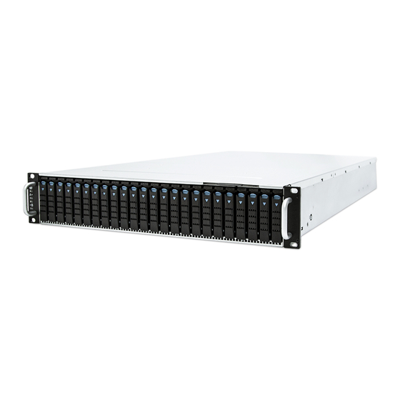
HA201-PV User Manual HA201-PV User Manual Chapter 1. Product Features HA201-PV is a 2U high density storage server with 24 hot swap bays for dual-port NVMe SSDs (U.2). For more information about our product, please visit our website at https://www.aicipc.com/en. -
Page 11: 1.2 Specifications
• 3 x8 slots (2LP, 1internal LP) • 1 x OCP Mezzanine card V2.0 Remote Management Processor Expansion Slots PCIe 3.0 (Notification: About OCP card, Please contact (per node) AIC Technical Support for additional information/details.) System management Management Rear I/O 2 x USB 3.0 Type A... -
Page 12: 1�3 Features
Chapter 1. Product Features 1�3 Features HA201-PV is a reliable 2U 2 node storage server barebone with 24 x 2.5-inch hotswap drives bays. This product is designed to accommodate the AIC-patented serverboard, Pavo, which supports two Intel® Xeon® Scalable Processors and 16 DDR4 DIMM to offer greater perfomance, efficiency, and utility for our customers. - Page 13 HA201-PV User Manual Chapter 1. Product Features Front Panel 24 x 2.5" hotswap drive bays Item Description System Power Button Secondary System Power LED System Warning LED Primary System Power LED System Warning LED Rear Panel Primary Node Secondary Node ...
- Page 14 HA201-PV User Manual Chapter 1. Product Features Major Components Top view Node top view...
-
Page 15: Chapter 2� Hardware Setup
Chapter 2� Hardware Setup Chapter 2. Hardware Setup HA201-PV User Manual 2�1 Central Processing Unit Setup The serverboard supports dual Xeon scalable processors and Socket P0 (LGA-3647). 2�1�1 Processor Installation To ensure a safe and easy setup, you need to prepare before installation: ... - Page 16 HA201-PV User Manual Chapter 2. Hardware Setup Processor Socket Assembly: The server board includes two processor sockets (LGA-3647), supports one or two of the Intel® Xeon® Processor Scalable Family and has a Thermal Design Power (TDP) of up to 165W on selected models.
- Page 17 Chapter 2. Hardware Setup HA201-PV User Manual The PHM sits level with the processor socket assembly. The PHM is NOT installed properly if it does not sit level with the processor socket assembly. Once the PHM is seated over the processor socket assembly, the four heat sink torque screws must be tightened in order as shown below.
-
Page 18: 2�2 System Memory
HA201-PV User Manual Chapter 2. Hardware Setup 2�2 System Memory 2�2�1 Dual Processor This server board supports up to sixteen DDR4 2400 and 2666 Registered ECC DRAM/ Load-Reduced DIMM (LRDIMM). DIMMC DIMMC DIMMJ DIMMJ DIMMB DIMMB DIMMH DIMMH DIMMA1 DIMMA1... -
Page 19: Recommended Dimm Installation Order
Chapter 2. Hardware Setup HA201-PV User Manual 2�2�2 Recommended Dimm Installation Order JDIMMC JDIMMJ JDIMMB JDIMMH JDIMMA1 JDIMMG1 JDIMMA2 JDIMMG2 DIMM Numbers DIMM ARRANGMENT CPU0 CPU1 CPU0 CPU0 CPU0 CPU0 CPU1 CPU1 CPU1 CPU1 2 DIMMs JDIMM_C JDIMM_J JDIMMD2 JDIMMK2... - Page 20 HA201-PV User Manual Chapter 2. Hardware Setup JDIMMC JDIMMJ JDIMMB JDIMMH JDIMMA1 JDIMMG1 JDIMMA2 JDIMMG2 JDIMM_C JDIMM_J JDIMM_B JDIMM_H CPU0 CPU0 CPU1 CPU1 JDIMM_A1 JDIMM_G1 JDIMM_D1 JDIMM_K1 JDIMM_F JDIMM_M JDIMMD2 JDIMMK2 JDIMMD1 JDIMMK1 JDIMME JDIMML JDIMMF JDIMMM JDIMMC JDIMMJ JDIMMB...
-
Page 21: Dimm Installation
Chapter 2. Hardware Setup HA201-PV User Manual 2�2�3 DIMM Installation Step 1 Unlock the dimm socket by pressing the retaining clips outward. Step 2 Insert the memory module into the slot. Make sure that the dimm notch is accurately positioned. -
Page 22: 2�3 Top Cover
HA201-PV User Manual Chapter 2. Hardware Setup 2�3 Top Cover Step 1 Slide the top cover in the direction of the red arrow. Step 2 Lift the top cover upward to remove. This information is provided for professional technicians only. -
Page 23: 2�4 Power Supply Unit Module
Chapter 2. Hardware Setup HA201-PV User Manual 2�4 Power Supply Unit Module Push the ejector to release the module. Pull the handle to remove the module out of the chassis. Push the replaced power supply unit into the chassis. Ensure that the module is hooked into the cage. -
Page 24: 2�5 Node
HA201-PV User Manual Chapter 2. Hardware Setup 2�5 Node Push the ejector to release the module. Pull the handle to remove the module out of the chassis. Push the replaced power supply unit into the chassis. Ensure that the module is hooked into the cage. -
Page 25: 2�6 Fan Module
Chapter 2. Hardware Setup HA201-PV User Manual 2�6 Fan Module Initiate the removal of the fan by unplugging the cables and connectors from the fan. Extract the fan by carefully dislodging the rubber connectors on the fan from the securing bracket. -
Page 26: 2�7 Hard Disk Drive
HA201-PV User Manual Chapter 2. Hardware Setup 2�7 Hard Disk Drive Press the release button the tray lever to loosen the lever. Pull the tray lever outward completely. Pull the tray out of the system. Insert the hard disk drive into the tray. Ensure that the dimples on the tray match the hard disk drive. -
Page 27: 2�8 Hdd Backplane Module
Chapter 2. Hardware Setup HA201-PV User Manual 2�8 HDD Backplane Module Detach the cables and hard disk drives from the backplane module. Release the module by shifting the hook. Dislodge the screws on the module. Lift the module upward to remove. -
Page 28: 2�9 Slide Rail Installation
HA201-PV User Manual Chapter 2. Hardware Setup 2�9 Slide Rail Installation Removing the inner slide rail. Pull the slide rail open by pressing the trigger downward. Pull chassis inner rail out Press the trigger down to release Mounting the inner side of the slide rail. - Page 29 Chapter 2. Hardware Setup HA201-PV User Manual Attach the outer of cabinet to the slide rail. Insert the stag into the upper and lower square holes on rail from the back of rail. Push the safety lock forward to secure the bracket. Be certain to check if the safety lock is in disenaged position before mounting the brackets.
- Page 30 HA201-PV User Manual Chapter 2. Hardware Setup Mount the chassis into the cabinet. Insert the inner side of chassis into the cabinet. Check if the ball retainer is fully opened before installing the chassis. It may cause catastrophic damage to the chassis if ball retainer is not in fully open position while mounting the chassis.
-
Page 31: Chapter 3� Motherboard Settings
Chapter 3� Motherboard Settings HA201-PV User Manual Chapter 3. Hardware Settings This section describes the jumpers, internal connectors, and internal LED settings on the Pavo motherboard. The motherboard layout and jumper settings are listed below. 3�1 Block Diagram... -
Page 32: 3�2 Content List
HA201-PV User Manual Chapter 3. Hardware Settings 3�2 Content List Connector and Header Location Connector and Header Location RJ45 Port for BMC management PMBUS Header COM Port by 3.5mm Phone Jack PCIe Slot (x24) 2 x USB 3.0 Type A... -
Page 33: 3�3 Placement
HA201-PV User Manual Chapter 3. Hardware Settings 3�3 Placement (For Pavo systems only. Rack not included.) CPU0 CPU0 CPU1 CPU1... -
Page 34: 3�4 Connector And Jumper
HA201-PV User Manual Chapter 3. Hardware Settings 3�4 Connector and Jumper 7a ~ 7b COM Header (J11, J12) 8 Front VGA Header (J7) 9 UID LED Header (J15) 9 10 UID_LED P5V_AUX 12 UART Header (J17) UART_RX UART_TX 11 Front I/O USB 3.0 Header... - Page 35 HA201-PV User Manual Chapter 3. Hardware Settings 22 Front Panel Header (J81) 25 PCIe Hot Plug SMB Header 26 PCIe Hot Plug SMB Header (J2001) (J2002) +3.3V_DUAL PWR_LED+ SMB_PEHPCPU0_SCL SMB_PEHPCPU1_SCL UID_LED+ SMB_PEHPCPU0_DAT SMB_PEHPCPU1_DAT UID_LED- PWR_LED- FAULT_LED+ HD_LED+ FAULT_LED- HD_LED- LAN1_ACT+...
- Page 36 HA201-PV User Manual Chapter 3. Hardware Settings A Clear CMOS Jumper (J10) E ME Recovery Mode Jumper (J35) Setting Setting Pin 1-2 Normal Default Short ME Recovery Mode Pin 2-3 Clear CMOS Open Normal Default B BMC Reset Jumper (J23)
- Page 37 HA201-PV User Manual Chapter 3. Hardware Settings J XDP Port Setting CPU0 Bypass chain control (J83) Setting Force Bypass of Pin 1-2 CPU0 Pin 2-3 Normal Default K XDP Port Setting CPU1 Bypass chain control (J84) Setting Force Bypass of...
-
Page 38: 3�5 System Led Indicator
HA201-PV User Manual Chapter 3. Hardware Settings 3�5 System LED Indicator 3�5�1 Front Panel Yellow System is On. System is in Standby; System is off, but has Power Blinking AC power. System has no AC power. Blue System ID activity is detected. -
Page 39: Rear Pch Lan
HA201-PV User Manual Chapter 3. Hardware Settings 3�5�3 Rear PCH LAN Green LAN1 activity is detected. LED5 LAN1 is not active. Green LAN1 link is detected. LED7 LAN1 is not linked. Green LAN0 activity is detected. LED6 LAN0 is not linked. -
Page 40: Rear Uid And Internal Led
HA201-PV User Manual Chapter 3. Hardware Settings 3�5�4 Rear UID and Internal LED UID activity is detected. LED1 UID is not active. BMC Rack LAN activity is detected (Only for LED2 Rack). BMC Rack LAN is not active (Only for Rack). -
Page 41: 3�6 Hdd Backplane
HA201-PV User Manual Chapter 3. Hardware Settings 3�6 HDD Backplane 3�6�1 Placement Top view JPWR4 JFAN JPIC JFRONT JSENSE JBEZ1 JBEZ2 JPMB JPWR1 Bottom view SAS CONN... -
Page 42: Connector And Jumper
HA201-PV User Manual Chapter 3. Hardware Settings 3�6�2 Connector and Jumper Power Supply Connector (JPWR4) 12V Output power connector (BM1,BM2) POS2 POS1 POS3 POS4 Front panel function connector (JFRONT) Power Supply Connector (JPWR1) Power IPMB Function (JPMB) Bezel function (JBEZ1,JBEZ2) -
Page 43: 3�7 Expander
HA201-PV User Manual Chapter 3. Hardware Settings 3�7 Expander 3�7�1 Placement JUB_MB JPMI_LOC JVBATT JVBATT JVBATT_I2C JVBATT_I2C Expander Expander JPIC_SMT JEXP_UART JEXP_UART JMB_PGD JMB_PGD JPWR_SW JPWR_SW JEXP_RST JEXP_RST JPWR1 JPWR1 JUSB_PIC JUSB_PIC JPWR2 JPWR2 JIPMB JIPMB JPSON_OK JPSON_OK JHDDPWR JHDDPWR... -
Page 44: Connector And Jumper
HA201-PV User Manual Chapter 3. Hardware Settings 3�7�2 Connector and Jumper Backplane PIC USB Header (JUSB_MB) Fan Connector (J7) (J8) Battery Connector (JVBATT) VBAT VBAT VBAT VBAT Power Connector (JPWR1, JPWR2) IPMB for Device (JIPMI_LOC) +12V SCL_LOCAL_IPMI +12V SDA_LOCAL_IPMI +12V... - Page 45 HA201-PV User Manual Chapter 3. Hardware Settings IPMB Connector (JIPMB) Console for Expander (JEXP_UART) SDA_LOCAL_IPMI SCL_LOCAL_IPMI Motherboard power on function (JPSON_OK) +5VSB_MB PIC Smart port (JPIC_SMT) POWER_PSON U6TXD MB_POK U6RXD Power Switch (JPWR_SW) Reset (JEXP_RST) Setting JEXP_RST EXP_RST Default high...
-
Page 46: Led Indicator
HA201-PV User Manual Chapter 3. Hardware Settings 3�7�3 LED Indicator SAS HD Link Status Green (On) Link up. Blue (Blinking) Activity detected. (LED_CN4, LED_ Link down. CN6, LED_CN7) Expander Blink Expander alive, 0.833Hz (12 seconds per Blue (Blinking) (LED2) cycle). -
Page 47: 3�8 Riser Card
HA201-PV User Manual Chapter 3. Hardware Settings 3�8 Riser Card 3�8�1 Placement J_PWRGD JPSU JIPMB JPWR JUSB SAS4 SAS4 SAS2 SAS2 JRE P0_I2C JRE P0_I2C PCIE4 PCIE1 SASHD1 JPWR1 EXT_SASHD1 SAS3 SAS1 PCIE3 SATA1 3�8�2 Connector and Jumper Node Power good connector (J_PWRGD) -
Page 48: Led Indicator
HA201-PV User Manual Chapter 3. Hardware Settings 3�8�3 LED Indicator HDD Access Green (Blinking) HDD Activity (HDD_ACT_LED) Riser IO Activity Green (Blinking) IO Activity (ACT_LED) Status Green (On) PCIE Status (STS_LED) Power LED Green (On) Power On LED (PWR_LED) Motherboard ID LED (ID_... -
Page 49: Chapter 4. Bios Configuration Settings
Chapter 4. BIOS Configuration Settings HA201-PV User Manual Chapter 4. BIOS Configuration Settings This chapter demonstrates how to configure the UEFI BIOS settings in your system device. You can enter the BIOS screen during system startup. To enter BIOS configuration settings, •... -
Page 50: 4�2 Bios Setup
HA201-PV User Manual Chapter 4. BIOS Configuration Settings 4�2 BIOS Setup 4�2�1 Menu Press and to select the options of the menu bar. Press Enter to access the option screen. Menu Description Main Displays basic system information and date & time. - Page 51 HA201-PV User Manual Chapter 4. BIOS Configuration Settings Step 2 There will be a message “Entering SETUP” displayed on the diagnostics screen. Step 3 Identify the BIOS version. NOTE For the official released version, the last digit of the BIOS version must end in a “0.“...
- Page 52 HA201-PV User Manual Chapter 4. BIOS Configuration Settings Step 4 Load Optimal Default Setting. Step 5 Save the setting and exit the BIOS setup utility.
-
Page 53: 4�3 Main
HA201-PV User Manual Chapter 4. BIOS Configuration Settings 4�3 Main Main Option Key: 4�3�1 Main Option Key Description System time Configures the current time. System date Configures the current date. -
Page 54: 4�4 Advanced
HA201-PV User Manual Chapter 4. BIOS Configuration Settings 4�4 Advanced Advanced Option Key: 4.4.1 Peripheral Configuration Peripheral Configuration PCIe SR-IOV Enable Disable PCIe ARI Enable Disable ARI Forward Enable Disable Spread Enable Disable Spectrum Redfish On/ Enable Disable 4.4.2 Video Configuration... - Page 55 HA201-PV User Manual Chapter 4. BIOS Configuration Settings MSR Lock Control Enable Disable Processor Configuration Extended APIC Enable Disable 128M 256M MMCFG Size 512M Common MMIO High Base RefCode Configuration MMIO High Granularity Size 256G 1024G Disable Minimum Serial Debug Message...
- Page 56 HA201-PV User Manual Chapter 4. BIOS Configuration Settings Check Platform Detect Enable Disable Erase-Arm NVDIMMs Enable Disable Restore NVDIMMs Enable Disable Memory Configuration Interleave NVDIMMs Enable Disable Custom Refresh Rate Min=0, Max=40 Auto 100 KHz SMB Clock Frequency 400 KHz...
- Page 57 HA201-PV User Manual Chapter 4. BIOS Configuration Settings Single Power Enable Disable Domain (SPD) Max Performance Boot performance Max Efficient mode Set by Intel Node Manager CPU P State Control Energy Enable Disable Efficient Turbo Turbo Mode Enable Disable CPU Flex Ratio...
-
Page 58: 4.4.4 Pch Configuration
HA201-PV User Manual Chapter 4. BIOS Configuration Settings 4.4.4 PCH Configuration PCH Configuration PCH Devices PCH state after G3 Last State SATA Controller Configure SATA as AHCI RAID Support Aggressive Link Power Enable Disable Management Alternate Device ID on Enable... - Page 59 HA201-PV User Manual Chapter 4. BIOS Configuration Settings Smart Response Enable Disable Technology PCH SATA Configuration 2 Seconds 4 Seconds RAID OROM prompt delay 6 Seconds 8 Seconds sSATA Controller Enable Disable Configure sSATA as AHCI RAID Support Aggressive Link Power...
- Page 60 HA201-PV User Manual Chapter 4. BIOS Configuration Settings SLP_LAN# Low on DC Enable Disable Power K1 off Enable Disable FPK Port 1-4 Enable Management Disable PCI Delay Enable Disable Optimization Compliance Test Enable Disable Mode PCI-E ASPM Support Per individual port...
- Page 61 HA201-PV User Manual Chapter 4. BIOS Configuration Settings Enable Disable Enable Disable Enable Disable NFER Enable Disable Enable Disable SEFE Enable Disable SENFE Enable Disable SECE Enable Disable PME SCI Enable Disable Hot Plug Enable Disable Advanced Error Enable Disable...
-
Page 62: H2O Ipmi Configuration
HA201-PV User Manual Chapter 4. BIOS Configuration Settings Auto Non Snoop Latency Manual Override Disable Non Snoop Min=0, Max=102 Latency Value PCH sSATA PCH PCIe LTR Configuration Configuration 1 ns 32 ns Non Snoop Latency 1024 ns 32768 ns Multiplier... -
Page 63: H2O Event Log Config Manager
HA201-PV User Manual Chapter 4. BIOS Configuration Settings 4.4.6 H2o Event Log Config Manager H2o Event Log Config Manager Console Serial Enable Disable Redirect VT_100 VT_100+ Terminal Type VT_UTF8 PC_ANSI 1200 2400 4800 9600 Baud Rate 19200 38400 57600 115200... -
Page 64: 4�5 Security
HA201-PV User Manual Chapter 4. BIOS Configuration Settings 4�5 Security Security Option Key: 4�5�1 Security Security Current TPM Not Detected TPM 1.2 TPM 2.0 Device TrEE Protocol Version Available Hidden Availability Disable and No operation Enable and Activate Operation Deactivate... -
Page 65: 4�6 Power
HA201-PV User Manual Chapter 4. BIOS Configuration Settings 4�6 Power Power Option Key: 4�6�1 Power Power Wake on PME Enable Disable... -
Page 66: 4�7 Boot
HA201-PV User Manual Chapter 4. BIOS Configuration Settings 4�7 Boot Boot Option Key: 4�7�1 Boot Boot Boot Type Dual Boot Type Legacy Boot Type UEFI Boot Type Quick Boot Enable Disable Quiet Boot Enable Disable Network Enable Disable Stack PXE Boot to... -
Page 67: 4�8 Exit
HA201-PV User Manual Chapter 4. BIOS Configuration Settings 4�8 Exit Exit Option Key: 4�8�1 Exit Save and Exit Exit Saving Changes Exit system setup and save your changes. Save Change Without Save your changes without exiting the system. Exit Exit Discarding Discard your changes when existing the system. -
Page 68: Chapter 5. Bmc Configuration Settings
Chapter 5. BMC Configuration Settings HA201-PV Chapter 5. BMC Configuration Settings Chapter 5. BMC Configuration Settings Insert Ethernet LAN cable into the BMC LAN port. There are two methods to setup BMC IP: BMC management port 5�1 BIOS Setup Step 1 BIOS SETUP Advanced H2O IPMI configuration BMC Configuration IPv4... - Page 69 HA201-PV Chapter 5. BMC Configuration Settings...
- Page 70 HA201-PV Chapter 5. BMC Configuration Settings Step 3 Type in the subnet mask address. Step 4 Type in the gateway address.
-
Page 71: 5�2 Login
HA201-PV Chapter 5. BMC Configuration Settings 5�2 Login NOTE This feature works with JAVA 6 Runtime installed Console Environment The IP source default is DHCP. You can change the IP source to DHCP or Static by the BIOS utility or the system check. -
Page 72: 5�3 Web Gui
HA201-PV Chapter 5. BMC Configuration Settings 5�3 Web GUI 5�3�1 Menu Bar Click to select the options of the menu bar. Menu Description The Dashboard page gives the overall information about the status of Dashboard a device. Sensor The Sensor Readings page displays all the sensor related information. -
Page 73: User Information And Quick Button
HA201-PV Chapter 5. BMC Configuration Settings 5�3�2 User Information and Quick Button The user information and quick access buttons are located at the top right corner. It displays the logged-in user, his/her privilege and the four quick buttons allowing you to perform different functions. -
Page 74: Fru Information
HA201-PV Chapter 5. BMC Configuration Settings 5�3�3 Dashboard: The Dashboard page gives the overall information about the status of adevice. 5�3�4 Sensor The Sensor Readings page displays all the sensor related information. 5�3�5 FRU Information The FRU Information page displays Basic Information, Chassis Information, Board Information and Product Information of the FRU device. -
Page 75: Logs And Report
HA201-PV Chapter 5. BMC Configuration Settings 5�3�6 Logs and Report The System Inventory page displays IPMI Event Log and Video Log. Click Logs and Reports from the menu bar. 5�3�7 Settings The Settings page allows you to access various configuration settings. -
Page 76: Kvm Mouse Setting
HA201-PV Chapter 5. BMC Configuration Settings 5�3�8 KVM Mouse Setting The KVM Mouse Setting page allows you to configure the mouse mode to relative, absolute, and other. • For Windows OS environment, set mode to absolute. • For Linux OS environment, set mode to relative. - Page 77 HA201-PV Chapter 5. BMC Configuration Settings Launch KVM:...
-
Page 78: Chapter 6� Technical Support
Chapter 6� Technical Support www�aicipc�com Taiwain, Global Headquarters South California, United States Address: No� 152, Section 4, Address: 21808 Garcia Lane Linghang N� Rd, Dayuan District, City of Industry, CA 91789, Taoyuan City 337, Taiwan United States Tel: +886-3-433-9188 Toll free: +7-4997019998 Fax: +886-3-287-1818 Tel: +1-909-895-8989 Sales Email: sales@aicipc�com�tw...
Need help?
Do you have a question about the HA201-PV and is the answer not in the manual?
Questions and answers