Table of Contents
Advertisement
Quick Links
Advertisement
Table of Contents

Related Manuals for BARTEC BENKE HYGROPHIL H 4230-12 Ex Zone II


Summary of Contents for BARTEC BENKE HYGROPHIL H 4230-12 Ex Zone II
- Page 1 HYGROPHIL ® H 4230-12 Ex Zone II Operating Instructions Softwareversion 1.042 BA 060207 BARTEC BENKE GmbH Schulstraße 30 94239 Gotteszell Deutschland Telefon +49(0)9929)-301-0 Telefax +49(0)9929)-301-112 E-Mail: gotteszell@bartec-benke.de Internet: www.bartec-benke.de...
-
Page 3: Table Of Contents
Contents C - 1 Table of Contents Contents Page Date of issue System description _________________________________ 1 Task and fields of use ________________________________ 1 Measurement principle _______________________________ 2 Structure of the humidity measurement system ____________ 2 1.3.1 Measuring chamber __________________________________ 4 1.3.2 Ejector ____________________________________________ 5 1.3.3... - Page 4 Contents C - 2 Contents Page Date of issue Pressure-reduction controller _________________________ 41 3.6.1 Assembly drawing __________________________________ 41 3.6.2 Settings __________________________________________ 42 Filling the water storage tank _________________________ 44 External water detector ______________________________ 45 3.8.1 Electrical connection ________________________________ 45 3.8.2 Calibration ________________________________________ 45 3.8.3 Installation ________________________________________ 46...
- Page 5 Contents C - 3 Contents Page Date of issue Error and warning messages ________________________ 87 PROFIBUS _______________________________________ 91 Framework structure ________________________________ 91 Standby mode _____________________________________ 92 Channel description _________________________________ 93 8.3.1 Service channel ____________________________________ 93 8.3.2 Measured value channel _____________________________ 94 8.3.3 Arithmetic value channel _____________________________ 95 8.3.4...
- Page 6 Copyright © 2018 by All rights reserved. Subject to change without prior notice. No part of this document may be reproduced, processed or distributed BARTEC BENKE in any form or by any means without the prior written permission of Schulstraße 30 BARTEC BENKE.
-
Page 7: System Description
System description System description Task and fields of use HYGROPHIL ® H 4230 is a measuring system for determining the amount of Task water vapour in air and other gases. In many processes, monitoring and controlling gas humidity is a must if you want to achieve a consistently high product quality, use energy efficiently and adhere to the regulations regarding emission limits. -
Page 8: Measurement Principle
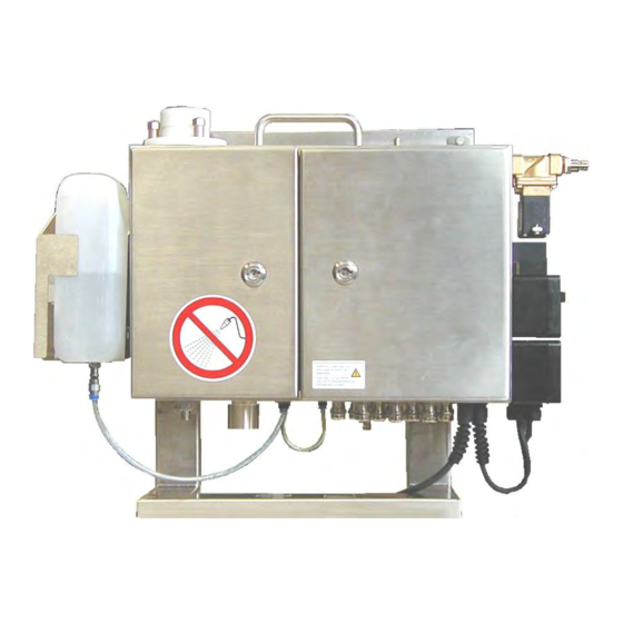
System description Measurement principle HYGROPHIL H 4230 works in accordance with the principle of psychromet- ® ric gas humidity measurement, measuring the difference in temperature be- tween two measurement sensors. The difference in temperature results from the fact that one of the two temperature sensors is moistened. Heat is re- moved from it by means of evaporation. - Page 9 System description Connecting cable for hose heating Gas sampling hose Earth connection Rinse valve Water container Measuring chamber enclosure Compressed air conditioner SILAS Controller Electronics enclosure Pressure control module Operating Instructions HYGROPHIL® H 4230-12 BA 060207...
-
Page 10: Measuring Chamber
System description 1.3.1 Measuring chamber Measuring chamber Water sensor Tube pump Ejector Pressure control module The venturi system and the water cylinder with the humidity sensors are ac- commodated in the measuring chamber. To begin with, the air to be measured flows through a venturi nozzle, in which the gas flow rate is determined by measuring the difference in pres- sure. -
Page 11: Ejector
System description With the specification HYGROPHIL H 4230-12 can the measuring gas be ® conveyed into the measuring chamber by using the present over-pressure. For this purpose a heatable pressure-reduction controller is to install before the gas sampling hose (see section 1.3.3). 1.3.2 Ejector The lower section of the measuring chamber contains the ejector, an air jet... -
Page 12: Silas-Controller
System description 1.3.8 SILAS-Controller The SILAS-Controller controls the flow of the scavenging gas and monitors the pressure inside the enclosure during rinsing and operating mode, to make possible the use of HYGROPHIL H in hazardous zone II. An over- pressure must be kept in the enclosure to prevent the device from inflowing of hazardous gases. -
Page 13: Control And Evaluation Electronics
System description 1.3.9 Control and evaluation electronics The signals for dry temperature, humid temperature, differential pressure and measuring chamber pressure are passed to the electronics unit, where a microprocessor is used to calculate the desired humidity measurement variables and monitor the equipment’s functions. The following measurement variables are recorded or calculated by the elec- tronics unit and can be displayed and saved on the PC: Dry temperature... -
Page 14: Controls And Displays
System description 1.3.10 Controls and displays When the enclosure door on the right is opened, the operator panel be- comes accessible, together with its display, signal lamps and operating keys. Display Keys Signal lamps 1.3.10.1 Keys The measurement variables are displayed by simply pressing a key. The keys that can be pressed to display the measurement variables are labelled appropriately. - Page 15 System description Display of the dry temperature of the incoming gas (corresponds to the gas sampling hose temperature) Display of the humid temperature of the incoming gas Display of the dew-point temperature of the gas to be measured VOL% Display of the volumetric water vapour content Display of the current partial water vapour pressure of the gas to be meas- ured Display of the absolute humidity of the gas to be measured...
- Page 16 System description Display of the temperature value of T1 (only if T1 is activated) external external Backlighting ON/OFF Display of the proportional valve regulation ratio Display of the internal temperature (T Standby (the pump speed is decreased by a factor of 10, while the setpoint value for the differential pressure is fixed) Key for changing the slave address and displaying the baud rate Test function for analogue outputs (former key F7 )
-
Page 17: Signal Lamps
System description 1.3.10.2 Signal lamps For the purpose of signalling various operating states, the panel contains six fields with symbols and a signal lamp for each. The heating (gas sampling hose) is switched on (red) The water pump is in operation (red) The proportional valve is opening (red) -
Page 18: Interfaces
System description 1.3.11 Interfaces Two electrically isolated analogue current outputs are available for the pur- Two analogue outputs pose of evaluating and processing the measured values. You can allocate any humidity measurement variables or auxiliary variables to these outputs as you wish. You are free to define the limits of the measurement ranges within the re- spective overall measurement range as you wish (see section 5.2.1). -
Page 19: Technical Data
System description Technical data Humidity measurement Measurement principle Psychrometric gas humidity measurement in line with the impact jet method Transducer PT 100/ 4-conductor in accordance with DIN IEC 751 Computational accuracy 0.01% Computing time Approx. 2s Settling time = 90s (for sudden change in SH from 10 to 190 g/kg) Air/gas flow rate Adjustable, max. - Page 20 System description Mechanical data Enclosure Stainless steel enclosure; protection rating IP64 in accordance with DIN 40050 Dimensions 450410150 mm (without mount) Assembly drill holes 347x330 mm, 47x13mm (M6) Weight Approx. 12.5 kg Connections Electrical connection Screw terminals 0.5-1.5 mm ; cable feed via M 16x1.5 cable gland Compressed air connection G 1/4"...
-
Page 21: Details When Ordering
System description Details when ordering 1.5.1 Basic equipment H 4230-10 HYGROPHIL Corrosion-proof, 115/230 V a.c. Scope of delivery: HYGROPHIL-H in accordance with order number, incl. compressed air conditioner, Type 4220-30 and 1 litre of surfactant Order number: 241887 1.5.2 Accessories gas tube, Type 4230-114 Measurement Flexible, water-resistant heating tube for feeding measurement gas without condensate... - Page 22 System description Water sensor external, Type 4230-103 For monitoring the fill level in the water storage tank Order number: 216424 Adapter for gas sampling hose, Type 4230-00-044 (DKR-3/8“ to NPT-1/4“) Order number: 214017 Adapter for gas sampling hose, Type 4230-00-046 (DKR-3/8“...
- Page 23 System description Standard filter, Type 4220-100 Including filter cartridge 150-µm CrNi Steel 1.4404 Order number: 208686 Gas sampling sensor Type SP 2000 GF 150 Order number: 214334 Sampling pipe for Gas sampling sensor Type SP 2000/SS Order number: 214333 Adapter for gas sampling hose 4220 to 4230, Type 4230-101 Order number: 216421 Operating Instructions HYGROPHIL®...
- Page 24 System description Wall holder, Type 4220-36 Order number: U 3401422036 Stand holder, Type 4220-35 Order number: U 3401422035 Pressure reduction controller with filter, Type 4230-118 Order number: 279270 Operating Instructions HYGROPHIL® H 4230-12 BA 060207...
-
Page 25: Spare Parts
System description 1.5.3 Spare parts Tube pump cartridge, Type 4230-104 Order number: 216422 Measuring chamber with ejector, Type 4230-301 Without probes Order number: 202383 Water sensor, Type 4230-302 For monitoring the fill level in the measuring cell Order number: 202823 Pump motor, Type 4230-303 Order number: 202409... - Page 26 System description Probe TT, Type 4230-304 Order number: 202411 Probe HT, Type 4230-305 Order number: 202410 Proportional valve, Type 4230-308 Order number: 202781 Display-/PROFIBUS board, Type 4230-401 Order number: 214369 Operating Instructions HYGROPHIL® H 4230-12 BA 060207...
- Page 27 System description Electronics board with power supply unit, Type 4230-400 Order number: 214369 Spare filter for standard filter Type 4220-106 150 µm, Cr-Ni steel 1.4404 Order number: U 116006 Replacement filter Type GF 150 for Gas sampling sensor SP 2000 0,1 µm Order number: 220232...
-
Page 28: Individual Parts For Measuring Chamber
System description 1.5.4 Individual parts for measuring chamber Level indicator incl. gasket Measuring cell incl. water connection incl. gaskets Type 4230-106 Type 4230-107 Order number: 232482 Order number: 232483 The measuring cell type 4230-107 is no longer delivered. It will be replaced by the further developed measuring cell type 4230-115 resp. -
Page 29: Consumables
System description Inlet strainer incl. gasket Type 4230-110 escape ejector chart no. 4230-00-054 Order number: 232458 Order number: 222563 Nut M5 Measuring cell-bracket incl. ejector Type 4230-111 for measuring chamber or cap fastener (2x3 pc per meas. chamber necessary) Order number: 202370 Order number: 232457... - Page 30 System description Operating Instructions HYGROPHIL® H 4230-12 BA 060207...
-
Page 31: Safety Precautions
Safety precautions Safety precautions HYGROPHIL units are produced in line with regulations currently in force and only leave the factory following thorough safety tests to ensure that they are in perfect condition. Please follow the instructions provided with regard to installing and operating the equipment. General information Please read the operating instructions prior to installing and starting up ... -
Page 32: Installation Location
Safety precautions Installation location When installing the equipment, make sure that you observe the permis- sible climatic and temperature conditions in line with the technical data. If exceptional conditions exist at the installation location, suitable measures must be taken to protect the equipment. Please look at the accessories we offer with respect to this. -
Page 33: Operating The Equipment
Safety precautions Operating the equipment Fluctuations in the mains voltage are only permissible within the scope of the values specified in the technical data. If the equipment is operated under exceptional conditions, voltage regulators must be used. Our Ser- vice department will be pleased to provide you with advice in this regard. - Page 34 Safety precautions Operating Instructions HYGROPHIL® H 4230-12 BA 060207...
-
Page 35: Installation
Installation Installation Depending on the local circumstances and purpose of use, HYGROPHIL ® H 4230 can be installed as either a stationary unit (wall mounting) or a mo- bile unit. The entire installation must be carried out by a specialist, taking into account and observing the regulations stipulated in DIN/VDE 100 and the relevant national provisions for setting up power installations rated for up to 1000 volts. -
Page 36: Wall Mounting
Installation Wall mounting Select an installation location and drill the four mounting holes in line with the specifications in the diagram. Fix four screws in the holes. Attach the two fixation bars to the rear of the device. ... -
Page 37: Using The Wall Mount
Installation Using the wall mount Instead of the fixation bars you can just as well fix the device by using the wall holder type 4220-36 (see section 1.5.2 Accessories). Attach the wall mount firmly to the wall. Please pay attention to the ... -
Page 38: Connection Instructions
Installation Connection instructions 3.3.1 Assignment of terminals External external Warning Error water OUT 1 OUT 2 Heating Mains PROFIBUS relay relay detector + – + – – +5V A B 0V L N PE L N PE 3.3.2 Mains connection Wiring must be carried out exclusively by specialists who are familiar ... -
Page 39: Temperature Sensors
Installation 3.3.3 Temperature sensors Only PT 100 resistance sensors are suitable as sensors (electric re- sistance 100 at 0 °C). Use a 4-strand shielded cable for the connection. Connect the shield on just one side of the terminals provided in order to avoid earth currents on the measuring unit. -
Page 40: Profibus
Installation 3.3.6 PROFIBUS Run the PROFIBUS cable through the two cable glands on the left. Connect the PROFIBUS cable to terminals 2 (PROFIBUS A) and 3 (PROFIBUS B). Jumper 1 Jumper 2 PROFIBUS A PROFIBUS B Shield If the unit is the last user in the PROFIBUS, the two jumpers must be closed. Jumper 1 Jumper 2 closed... -
Page 41: Mounting The Gas Sampling Hose
Installation Mounting the gas sampling hose In order for the HYGROPHIL unit to be operated, it is vital that the gas sam- pling hose is mounted precisely. You should therefore observe the following instructions. Before mounting the gas sampling hose, make sure that it is designed for the same voltage as the unit. - Page 42 Installation wrong right Avoid buckling and bending stress! Use saddles or rolls with an appro- priate diameter. Avoid compressing or stretching the hose. Use elbows at the connections. Avoid torsional movements during mounting. Make sure that the axes of the hose run parallel and that the hose is not twisted.
-
Page 43: Mounting Sequence
Installation 3.4.2 Mounting sequence Screw the M 48 plastic knurled nut to the gas sampling hose mounting nut on the unit (A/F 47). Push the gas sampling hose stub carefully into the opening on the top of the unit. ... -
Page 44: Compressed Air Connection
Installation Compressed air connection A compressed air connection is required only if HYGROPHIL H 4230-112 ® cannot be operated with the over-pressure of the measuring gas. Do not connect any supply to the compressed air connection at the bottom side of the device when operating with over-pressure! Do not connect any supply when operating with over-pressure! The compressed air connection should deliver maximum 17.5 Nl/min at a... -
Page 45: Mounting Sequence
Installation The following diagram illustrates the interdependence between negative pressure and admission pressure. Required admission pressure at max. possible negative pressure Negative pressure in hPa 3.5.1 Mounting sequence Connect the compressed air supply to the compressed air connector stub on the measuring unit. If the available supply pressure amounts to 5 bar or more, the compressed air conditioner must always be used. -
Page 46: Setting The Ejector's Operating Pressure
Installation Install the parts in the following order starting from the compressed air source: manually actuated valve - reducing valve - HYGROPHIL H 4230. ® A maximum of 12 bar is allowed in the compressed air supply line upstream of the reducing valve. The compressed air coupling supplied with HYGROPHIL ®... -
Page 47: Pressure-Reduction Controller
Installation If you have installed HYGOPHIL properly, you can start up the equipment as described in section 4.1. Please note the following points with regard to set- ting the operating pressure: Set the pressure at the compressed air conditioner’s reducing valve to a minimum of 2 bar to begin with and start measuring. -
Page 48: Settings
Installation 3.6.2 Settings Configuration For operating with over-pressure you must deactivate ejector operating. Start programming mode (see section 5.1.2). Open the menu EQUIP. CONF. (see section 5.2.4). Open the submenu FLOW-CONTR (see section 5.2.4.5) and switch off the compressed air control. - Page 49 Installation During the start sequence of the device you must readjust this value until the final operating parameters are achieved. Plug the bypass-jumper that deactivates the SILAS function. Turn the switch S2 into position 9. This will deactivate monitoring of the pressure inside the enclosure and you can observe the display of HYGROPHIL H when the enclosure door is opened.
-
Page 50: Filling The Water Storage Tank
Installation Filling the water storage tank In order to operate HYGROPHIL H 4230, you must pour demineralised wa- ® ter (extracted using the ion exchange procedure) or boiler feed water into the storage tank. It does not have to be distilled water. For each litre of water, add 5...10 ml of surfactant. -
Page 51: External Water Detector
Installation External water detector You can install an external water detector for the purpose of monitoring the level in the water tank. The water detector is available as an optional extra. Connecting cable Sensitivity setting 3.8.1 Electrical connection Insert the cable of the external water detector through the third cable ... -
Page 52: Installation
Installation 3.8.3 Installation Use two M 3 bolts and nuts to fix the external water detector to the inner side of the mounting strap (front side of the tank attachment) with the sensor side facing the tank. Then put the tank back in. ... -
Page 53: Operation
Operation Operation Start-up Before starting up HYGROPHIL H 4230, please check again that the follow- ® ing conditions are met. 1. Power supply – The mains voltage must correspond to the operating voltage of HYGROPHIL H 4230 and all components (gas sampling hose, filter, ®... -
Page 54: Configuration
Operation Configuration Under various operating conditions it will be necessary to select or change certain settings. All changes – with the exception of setting up the com- pressed air supply (see section 3.5.2) – are made through programming. Programming is described in chapter 5. Changing the slave address The default slave address is 100. -
Page 55: Programming
Programming Programming You can program HYGROPHIL 4230 to prepare it for use in your existing measurement and operation conditions. An overview of the menu structure in programming mode can be found on page 51. General notes 5.1.1 Interaction During programming, the user interacts with the equipment by answering questions with alternative answers. -
Page 56: Programming Process
Programming 5.1.2 Programming process You start programming mode by pressing the PROG key. Once program- Start programming mode ming mode has been started, all of the unit’s functions – including the heat- ing and air flow controls – switch to standby mode. When you switch to programming mode, you are first requested to enter Password your password. - Page 57 Programming PROG Operating mode PASSWORD _*** ? PRG-OUTPUT? 1/0 HOSE-PAR? 1/0 SET PUMP? 1/0 EQUIP.CONF.? 1/0 SET-LIMITS ? 1/0 PRG-OUTPUT HEATING-PARAMET PUMP-CONTROL EQUIPM.-CONFIG LIMIT-CONTROL ENABLE ? 1/0 xp=3 PAUSE-TIME=30 T1 extern ? 1/0 LIMIT TASK ? 1/0 PRG-OUTPUT HEATING-PARAMET EQUIPM.-CONFIG LIMIT-CONTROL CHANNEL 1 ? 1/0 w=120...
-
Page 58: Changing The Program Parameters
Programming Changing the program parameters This section explains the exact procedure for programming in all the menus. The order in which the menus are dealt with here is the same order in which they appear in the display in programming mode after you have entered your password. -
Page 59: Programming The Hose Heating Parameters
Programming 0 or ENTER Don’t make any changes, go to the next menu PRG-OUTPUT (hose heating parameters) CHANNEL 2 ? Change the programming of analogue output 2 Analogue output 2 is programmed in the same way as analogue output 1. 5.2.2 Programming the hose heating parame- ters... -
Page 60: Programming The Pump Control
Programming Example The example illustrated gives rise to the following values for a dew-point temperature of 70 °C: - Minimum gas sampling hose temperature = 87 °C - Ideal gas sampling hose temperature = 100 °C - Maximum gas sampling hose temperature = 120 °C 0 or ENTER Don’t make any changes, go to the next menu (pump ... -
Page 61: Programming The Equipment Configuration
Programming 5.2.4 Programming the equipment configura- tion 0 or ENTER Don’t make any changes, go to the next menu (limit monitoring) EQUIP.CONF. ? Change the programming of the equipment configura- tion 5.2.4.1 Temperature sensors HYGROPHIL H 4230 contains two temperature measuring circuits for the following temperature ranges: 0...200 °C external... -
Page 62: Water Detector
Programming 5.2.4.3 Water detector If the water falls below the internal water detector level, the message WATER-ERROR appears. The pump is then switched to filling mode until the required level is reached again. The message is also output if the exter- nal water detector responds. -
Page 63: Flow Setting
Programming 5.2.4.6 Flow setting For controlling the flow you can set a nominal value for differential pressure Don’t make any changes ENTER EQUIPM.-CONFIG Set a nominal value for DP SET FLOW ? 1/0 No nominal value for DP, switch to next menu. ... -
Page 64: Reference Pressure
Programming 5.2.4.7 Reference pressure Under exceptional operating conditions, the air pressure in the measuring chamber may deviate from the pressure at the point where the measurement gas is extracted. This is usually the case, for instance, if long gas sampling hoses need to be laid. -
Page 65: Limit Monitoring
Programming 5.2.5 Limit monitoring For measured values or arithmetic values you can define limits within the re- spective scale. If the value exceeds or falls below a defined limit, the warn- ing relay is activated and the ERROR LED lights up. 0 or ENTER Don’t make any changes, quit programming mode ... - Page 66 Programming Operating Instructions HYGROPHIL® H 4230-12 BA 060207...
-
Page 67: Maintenance
Maintenance Maintenance General information HYGROPHIL 4230 is as good as maintenance-free. The only maintenance ® necessary during operation is to refill the water tank and add a surfactant. Depending on the conditions of use, it may be necessary for the measuring chamber and any filters installed to be cleaned periodically. -
Page 68: Testing The Analogue Outputs
Maintenance Testing the analogue outputs With a precise mA-meter you can test the analogue outputs. For it you must call up a test mode (press key F7 ). In this mode you can enter a current for each analogue output. The entered value is to measure at the corresponding output. -
Page 69: Types Of Dirt
Maintenance 6.3.2 Types of dirt The measuring chamber may be contaminated in particular by the following types of dirt: Oils and grease Due to the high temperature of the air to be measured, these substances are often present in a gaseous state and are therefore able to pass through the filter. -
Page 70: Disassembling The Measuring Chamber
Maintenance 6.3.3 Disassembling the measuring chamber Make sure that the equipment is switched off. Remove the gas sampling hose (detach the nut and pull out the gas sampling hose carefully upwards). In order to disassemble the measuring chamber you need to remove all wires and hoses that run to the measuring chamber. - Page 71 Maintenance Remove the water supply hose (this is done by pressing the white catch upwards and simultaneously pulling out the hose downwards). Detach the compressed air hose (this is done by pushing in the blue catch and simultaneously pulling out the hose). Press in compressed air hose catch, pull out hose...
- Page 72 Maintenance Pull out the ejector outlet downwards while at the same time twisting it. Detach the three upper M 5 /A/F 14 mounting nuts. Operating Instructions HYGROPHIL® H 4230-12 BA 060207...
- Page 73 Maintenance Pull the measuring chamber carefully downwards and take it out of the enclosure. Operating Instructions HYGROPHIL® H 4230-12 BA 060207...
-
Page 74: Dismantling The Measuring Chamber
Maintenance 6.3.4 Dismantling the measuring chamber Pull the two T-pieces out of the measuring chamber enclosure together with the water detector. Detach the three lower nuts (M 5 / A/F 14). Operating Instructions HYGROPHIL® H 4230-12 BA 060207... - Page 75 Maintenance Remove the two parts of the lower measuring chamber section pulling downwards. Place the measuring chamber on the three lower threaded pins and press the middle measuring chamber section downwards. Operating Instructions HYGROPHIL® H 4230-12 BA 060207...
-
Page 76: Changing The Humid Temperature Sensor
Maintenance Push the measuring cell downwards and out of the middle measuring chamber section. Attention: never press the “tulip” but press carefully beside the “tulip” to the measuring cell by using a screw driver or a simi- lar tool. 6.3.5 Changing the humid temperature sen- Detach the knurled nut from the sensor mount and carefully extract the... -
Page 77: Changing The Dry Temperature Sensor
Maintenance 6.3.6 Changing the dry temperature sensor You can change the dry sensor without having to disassemble the measur- ing chamber. Detach the connector’s knurled nut and remove the plug-in connector. Detach the knurled nut from the sensor mount and carefully extract the ... -
Page 78: Cleaning The Measuring Chamber
Maintenance 6.3.7 Cleaning the measuring chamber Upper flange The measuring chamber’s upper flange, which has been left in the enclo- sure, can be cleaned using a lint-free cloth. Pull it to and fro through the opening. Upper measuring chamber section Extract the dry temperature sensor (detach the white knurled nut and care- fully extract the sensor). - Page 79 Maintenance Be careful with the measuring cell. The ceramic ring in the measuring cell is brittle and can therefore be broken easily. Lower measuring chamber section with ejector You should not dismantle the ejector because it is adjusted at the factory in order to maximize efficiency.
- Page 80 Maintenance Clean both parts of the ejector. Use a piece of cloth or brushes and a detergent that is able to dissolve the respective film of dirt. Never use sharp-edged objects to clean the ejector. The ejector gets waste if its surface is scratched.
- Page 81 Maintenance Measuring cell new Measuring cell type 4230-107 type 4230-115 / 116 Component parts of the measuring chamber Operating Instructions HYGROPHIL® H 4230-12 BA 060207...
-
Page 82: Assembling The Measuring Chamber
Maintenance 6.3.8 Assembling the measuring chamber Once parts have been cleaned or exchanged, the measuring chamber is as- sembled again by reversing the steps taken to disassemble it. Please observe the following instructions during assembly. The measuring chamber can only be assembled if the component parts ... -
Page 83: Internal Water Detector
Maintenance Put the assembled measuring chamber back in the enclosure and tight- en the upper mounting nuts. Insert the ejector outlet through the enclosure from the bottom and push it into the lower section of the measuring chamber. Then screw on the outlet connection (knurled screw) and thereby press ... -
Page 84: Water Pump
Maintenance If you use a new water detector, calibrate it prior to assembly in the same way. Sensor Sensitivity setting More sensitive Water pump The water is pumped from the storage tank to the measuring cell using a peristalsis hose pump. The pump can be changed quite easily when required. -
Page 85: Gas Sampling Hose
Maintenance Gas sampling hose The gas sampling hose does not usually require any maintenance. The inner hose is made of a material that hardly any dirt clings to. In the case of irregular system operation, for example if there is air flow rate while the measuring system is switched off, dirt may collect in the hose. -
Page 86: Cleaning The Filter
Maintenance 6.7.2 Cleaning the filter Depressurize the pipe before removing the condensate separator! Press the ratchet lever down and turn the condensate separator 45° to the left or to the right. Pull the condensate separator down to remove it. Rinse the condensate separator carefully us- ing this opportunity. -
Page 87: Pressure Reduction Controller
Maintenance Clean the filter. Only use water for cleaning. Do not use alcohol or any aggressive chem- icals! If you notice that the filter is damaged or extremely contaminated use a new one please. Insert the cleaned or a new filter. ... -
Page 88: Changing Fuses
Maintenance Changing fuses The two fuses are located in the electronics enclosure (door on the right). Press in the fuse holder using a screwdriver and turn it a little anticlock- wise. Fuse 2 : Heating T 6A Fuse 1 : Electronics supply MT 2A Extract the fuse holder and exchange the fuse. -
Page 89: Replacing The Display-/ Profibus-Board
Maintenance 6.10 Replacing the Display-/ Profibus- board Disconnect the device from power supply before starting any work at the electronics. Observe the safety precautions according to chapter 2. Disconnect the two connectors and unscrew the four attachment screws. ... -
Page 90: Replacing The Electronics Board
Maintenance 6.11 Replacing the electronics board To replace the electronics board you must first dismount the display-/ profibus-board. Follow the instructions according to section 6.10 to this. To avoid mistakes when reassembling you should note the positions of all connections or mark them distinctive. - Page 91 Maintenance Connect the pressure hoses to their nipples according to the figure be- low. Reassemble the display-/ profibus board according to section 6.10. Operating Instructions HYGROPHIL® H 4230-12 BA 060207...
-
Page 92: Replacing The Proportional Valve
Maintenance 6.12 Replacing the proportional valve First dismount the display-/ profibus-board and the electronics board (fol- low the instructions according to section 6.10 and 6.11). Disconnect the two blue hoses from the proportional valve For this press in hose catch at the nipple and pull out the hose at the ... -
Page 93: Error And Warning Messages
Error and warning messages Error and warning messages While HYGROPHIL H is being operated, messages are output on the dis- ® play and the ERROR-LED lights up whenever faults occur and whenever operating values exceed or fall below the required values. In addition, either the error relay or the warning relay is activated. - Page 94 Error and warning messages Message Relay Causes Actions FLOW MIN !! Error relay Although the proportional valve is Upon start-up: fully open, too little air is being Increase admission pressure at pumped through the measuring the reducing valve (up to a max- chamber.
- Page 95 Error and warning messages Message Relay Causes Actions OUTRANGE SP !! Warning relay The pressure pick-up for the Read the value for SP ( SP key) measuring chamber is not deliv- and compare it with the external ering plausible values (<500 hPa barometer if appropriate or >...
- Page 96 Error and warning messages If a measurement value or arithmetic value lies above or below the value de- fined in the SET LIMITS menu, the warning relay is activated and the „Fault“ LED lights up. The current measurands are present at the analog output. In the following cases will the last measured values be kept („frozen“) at the analog outputs: 1.
-
Page 97: Profibus
PROFIBUS PROFIBUS HYGROPHIL H 4230 contains a certified PROFIBUS DP interface. All field bus-specific equipment data is listed in the GSD file „BARx077D.gsd“. The file is supplied with the product on a storage medium. The module specified there for I/O allows the user to request data by handshake. Framework structure The framework structure must comply with the following guidelines: Byte 0... -
Page 98: Standby Mode
PROFIBUS Bytes 4/5, offset high/low Input: The offset of a variable is to be taken from the channel description for the equipment (see section 8.3). Example: a read operation to data address 0x0020 with an offset of 0x0000 would deliver the dew point, whereas an offset of 0x0004 would address the measured value for the relative humidity (see channel description). -
Page 99: Channel Description
PROFIBUS Channel description 8.3.1 Service channel DaAdr (hex) Identifier Memory type Read-out Format Reset RAM read/write Char Status field RAM read bin. or hex Long Standby mode RAM read/write Char DaAdr $03: Reset Format: char Writing 0xFF triggers reset on the entire equipment (including PROFIBUS in- terface) DaAdr $0A: Status field Format: long... -
Page 100: Measured Value Channel
PROFIBUS 8.3.2 Measured value channel DaAdr (hex) Identifier Memory type Read-out Format Measured values RAM read/write Float [0] Preset SP EEPROM read/write dec Float Preset T1 EEPROM read/write dec Float external Activate T1 EEPROM read/write hex Char external DaAdr $10: Measured value Format: Array [1...6] of Float Order of the measured values: Designation... -
Page 101: Arithmetic Value Channel
PROFIBUS 8.3.3 Arithmetic value channel DaAdr (hex) Identifier Memory type Read-out Format Arithmetic values RAM read Float[9] Use preset T1 value EEPROM read/write Char external Use preset SP value EEPROM read/write Char DaAdr $20: Arithmetic value Format: Array [1...9] of Float All arithmetic values in the following order: Designation Identifier... -
Page 102: Output Channel
PROFIBUS 8.3.4 Output channel DaAdr (hex) Identifier Memory type Read-out Format OutputControlStatus RAM read Char[3] Setpoint@ RAM read Float[3] OutputChConfig EEPROM read/write Record[3] Fullscale EEPROM read/write Float[3] Zeropoint EEPROM read/write Float[3] DaAdr $31: OutputControlStatus Format: Array [1...3] of Char Value OK SignalHigh SignalLow Free... - Page 103 PROFIBUS DaAdr $39: OutputChConfig* Format: Array [1...2] of Record Output1 Output2 EnableBits: Char (*Offset = 0*) Char (*Offset = 4*) FunctionBits: Char (*Offset = 1*) Char (*Offset = 5*) SetpointNo: Char (*Offset = 2*) Char (*Offset = 6*) ErrorState: Char (*Offset = 3*) Char (*Offset = 7*) End;...
-
Page 104: 1-Channel Parameters
PROFIBUS DaAdr $3B: Fullscale Format: Array [1...2] of Float Before you can write this variable you must first change to standby mode. Setpoint value that corresponds to 100% in the output. Default: Setpoint [x] Designation/unit Value DT/°C HT/°C DaAdr $3C: Zeropoint Format: Array [1...2] of Float Before you can write this variable you must first change to standby mode. - Page 105 PROFIBUS DaAdr $42: HeatingContolStatus Format: Record Statuschar: Char; dummy; Char; ON time; Integer; OFF time; Integer; End; Statuschar: Errortimeout Control bit HoseError Free D limit PID active I limit for control 1 = Controller is switched on and working 0 = Controller off Errortimeout: 1 = Error-tolerant period expired 0 = Equipment in normal operation Control bit for control (function display for heating)
-
Page 106: 2-Channel Parameters
PROFIBUS DaAdr $48: T2 correct config Format: Char Before you can write this variable you must first change to standby mode. 0x00 = No correction of HT based on the T2 measurement 0x80 = HT is corrected based on T2 (internal temperature) (default) DaAdr $4c: Timeout activating Format: Char Before you can write this variable you must first change to standby mode. - Page 107 PROFIBUS ControlStatusChar: Used to control the valve within the unit, especially to switch off the valve temporarily when errors occur. Overrides the PropValveConfig up to reset. Control Status FullOpen FullClose Free FullOpen FullClose Free 1 = Controller is switched on and working 0 = Controller off FullOpen: 1 = Valve completely open (Control) or opened (Status)
- Page 108 PROFIBUS DaAdr $57: EquipmentControlStatus Format: Char Free Free ExternWater Free Free Free InternWater Free Error Error ExternWater: 1 = External level sensor reports „no water“ InternWater Error: 1 = Internal level control reports „no water“ If the corresponding inputs in EquipmentChConfig (DaAdr $4C) have not been released, the status bits are left at '0'.
- Page 109 PROFIBUS DaAdr $5a: Limit LOW Format: Float Before you can write this variable you must first change to standby mode. Lower value of the limit monitoring „LOW LIMIT“. (Default: 0) DaAdr $5b: Limit HIGH Format: Float Before you can write this variable you must first change to standby mode. Upper value of the limit monitoring „HIGH LIMIT“.
-
Page 110: Examples
PROFIBUS Examples Two sample sequences will be used to illustrate how to read from HYGRO- PHIL H (querying the dew point) and how to write to HYGROPHIL H (chang- ing to standby mode). 8.4.1 Reading from HYGROPHIL H Querying the dew point According to the channel description the dew point can be found at data ad- dress 0x20 with offset 0. -
Page 111: Writing To Hygrophil H
PROFIBUS 8.4.2 Writing to HYGROPHIL H Changing from normal operation to standby mode According to the channel description you can change to standby mode by writing 0x50 to data address 0x0B. Write request from the PROFIBUS master: 0x50 0x01 0x00 0x000B 0x00 0x01... - Page 112 Operating Instructions HYGROPHIL® H 4230-12 BA 060207...
Need help?
Do you have a question about the HYGROPHIL H 4230-12 Ex Zone II and is the answer not in the manual?
Questions and answers