Table of Contents
Advertisement
Advertisement
Table of Contents

Related Manuals for BARTEC BENKE HYGROPHIL F 5673


Summary of Contents for BARTEC BENKE HYGROPHIL F 5673
- Page 1 ® HYGROPHIL F 5673 Series A Operating manual Software version 1.8.x 387896MDHEN BARTEC BENKE GmbH Schulstraße 30 94239 Gotteszell Deutschland Telefon +49(0)9929)-301-0 Telefax +49(0)9929)-301-112 E-Mail: gotteszell@bartec-benke.de Internet: www.bartec-benke.de...
-
Page 3: Table Of Contents
Contents C - 1 Contents Contents Page Issue date System description ____________________________________________ 1-1 Measurement principle, Function and applications _____________________ 1-1 09.11.2011 Declaration of Conformity ________________________________________ 1-2 19.05.2011 Layout of the humidity measurement system _________________________ 1-4 1.3.1 Operator controls and display elements _____________________________ 1-4 1.3.1.1 Keyboard _____________________________________________________ 1-4 Key functions __________________________________________________ 1-5... - Page 4 Contents C - 2 Contents Page Issue date Data export __________________________________________________ 4-14 4.4.1 Copy data ___________________________________________________ 4-14 17.03.2011 4.4.2 Converting data ______________________________________________ 4-15 4.4.3 Export service information to an external data medium ________________ 4-16 17.03.2011 Programming _________________________________________________5-1 General instructions _____________________________________________5-1 Calling up programming mode _____________________________________5-2 Selecting and opening the menu ___________________________________5-3 Editing parameters ______________________________________________5-4...
- Page 5 Contents C - 3 Contents Page Issue date Error handling ________________________________________________ 6-1 Limit transgressions ____________________________________________ 6-1 Warnings _____________________________________________________ 6-2 Errors _______________________________________________________ 6-2 HELP key ____________________________________________________ 6-3 Maintenance _________________________________________________ 7-1 Cleaning the sensor ____________________________________________ 7-1 17.04.2013 Bus systems _________________________________________________ 8-1 Modbus ______________________________________________________ 8-1 26.04.2013 Profibus ______________________________________________________ 8-6 04.06.2012...
- Page 6 All rights reserved and subject to change. Copyright © 2015 Duplication, processing and distribution of this document, by BARTEC BENKE GmbH including parts thereof, is prohibited without the prior Schulstraße 30, written consent of BARTEC BENKE. D-94239 Gotteszell Document: 387896MDHEN valid from: 10.11 Revision: Software version 1.8.x...
-
Page 7: System Description
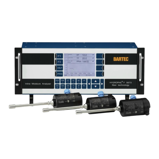
System description System description Measurement principle, Function and applications ® HYGROPHIL F 5673 is a high-quality, microprocessor-controlled fibre-optic hygrometer for measuring the moisture or trace humidity at low dew-point temperatures in gases and liquids. ® HYGROPHIL F 5673 works in multi-channel operation with a temperature- compensated fibre-optic sensor developed especially for measuring the moisture content in gas mixtures and liquids. - Page 8 System description Declaration of Conformity HYGROPHIL® F 5673 Operating manual, Software version 1.8.x, 387896MDHEN(14.06.2013)
- Page 9 System description HYGROPHIL® F 5673 Operating manual, Software version 1.8.x, 387896MDHEN(14.06.2013)
-
Page 10: Operator Controls And Display Elements
System description Layout of the humidity measurement system The measurement system consists of an evaluation unit and up to three hu- midity sensors. The evaluation unit is designed as a 19“rack which can take several plug-in units. The evaluation unit can also be installed as a desktop device. The humidity sensor consists of a sensor layer and an integrated tempera- ture sensor, the fibre-optic cable and the plug connector, which also contains the sensor´s adjustment data. -
Page 11: Key Functions
System description Key functions Indication of the water vapour content [Vol%], optional relative humidity [RH] VOL% (see section 4.3.1.3) Indication of the water vapour content in parts per million volume or in parts per million weight Indication of the Dewpoint Temperature Indication of the Frost Point Temperature Indication of the Moisture Content [mg/m ] or [lb/MMscF]... - Page 12 System description The four keys to the right of the display are not labelled. Depending on the operating status of the measurement system, different functions are as- signed to them. The current function is marked by a symbol next to the key in the display (for the meaning of the symbols see section 5.1).
-
Page 13: Display
System description 1.3.1.2 Display A graphic display screen designed as a touch-screen is used for display purposes. Some functions are operated by means of key functions located on the dis- play screen in dependence on the situation. HYGROPHIL® F 5673 Operating manual, Software version 1.8.x, 387896MDHEN(14.06.2013) -
Page 14: Interfaces
System description 1.3.2 Interfaces Channel boards Analog/Digital I/O Ex Relay module Channel 1 Channel 2 Channel 3 Polychromator Power supply module CPU module Interface module Temperature sensor (PT100) Pressure sensor (4...20 mA) 3x Current output -sensor (4...20 mA) Current output Ex i Relay outputs see section 1.4.7 HYGROPHIL®... - Page 15 System description HYGROPHIL® F 5673 Operating manual, Software version 1.8.x, 387896MDHEN(14.06.2013)
- Page 16 System description 1-10 HYGROPHIL® F 5673 Operating manual, Software version 1.8.x, 387896MDHEN(14.06.2013)
-
Page 17: Technical Data
System description 1-11 Technical data 1.4.1 Evaluation unit F 5673 Evaluation unit Display ranges Measurement variable Lower range limit Upper range limit (not the measuring range) Vol% [ppm] 25000 [°C,°F,K] -100 [°C,°F,K] -100 [mg/m 30000 [lb/MMscF] [hPa] [°C,°F,K] [bar,PSI,..] [nm] Auxiliary variables The temperature (TT) at the measuring point is measured via a sensor inte- grated in the humidity sensor or entered by hand. -
Page 18: Cpu Plug-In Unit Type 5673-113
System description 1-12 1.4.2 CPU plug-in unit type 5673-113 Electrical data 5.5 V ± 2 % Operating voltage CPU Power consumption 800 mA Fuse of battery 3.5 A Interfaces USB 2.0 Host OHCI Ethernet 100 MBit 5x up to 115200 Bit/s, 3.3 V LVTTL Serial interfaces 2x up to 460800 Bit/s, 3.3 V LVTTL Elektronics... -
Page 19: Analog I/O Ex Type 5673-114
System description 1-13 1.4.5 Analog I/O Ex type 5673-114 Electrical data Operating voltage for CPU DC 5.5 V ± 2 % 200 mA, fuse 400 mA Operating voltage for sensor supply DC 24 V ± 5 %, max. 480 mA, fuse 1 A PT-100 [EEx ia] Type Pt-100 (4 wires), l 1 mA -50...+100 °C... - Page 20 System description 1-14 Shield Shield Shield Shield Shield Analog I/O Ex Type 5673-114 To the cables of the analog inputs IN1, IN2 and to the cable of the analog EMC: output OUT Source must be fixed ferrite noise filters (order no. 275368) (see section 3.2).
-
Page 21: Interface Module Type 5673-110
System description 1-15 1.4.6 Interface module type 5673-110 Electrical data Operating voltage for CPU DC 5,5 V ± 2 % Operating voltage for interfaces DC 24 V ± 5 % 3 x Analog output Current range 0/4 – 20 mA, galvanically isolated, source Resolution 0,0003 mA <... - Page 22 System description 1-16 Interface module Serial Out (s. 5.6.9) MODBUS RTU Select the interface for MODBUS in the „Modbus/Profibus“ menu (see section 5.6.7). To all cables of the analog outputs OUT1, OUT2, OUT3 must be fixed ferrite EMC: noise filters (order no.
-
Page 23: Relay-Interface Module Type 5673-115
System description 1-17 1.4.7 Relay-Interface module Type 5673-115 Electrical Data DC 5.5 V ± 2 % 70 mA fuse 500 mA Operating voltage CPU DC 24 V ± 5 % 60 mA fuse F3A Operating voltage 24 V Relays Type Change-over contact Insulation 1500 vrms... -
Page 24: Polychromator Plug-In Unit Type 5673-302
System description 1-18 1.4.8 Polychromator plug-in unit type 5673-302 Electrical data Operating voltage DC 5.5 V Power consumption 200 mA Connection type ST plug optical (sensor) Interface USB 12 Mbit/s (full speed) Measuring range ca. 720...870 nm 2000 Pixel ≅ 0.17 nm/Pixel Resolution Ambient conditions Operating temperature... - Page 25 System description 1-19 Sensor L 166x, Dew-point measuring range 20000 10000 1000 -100 Gas temperature TT [°C] Function range extrapolated Out of calibrated range Calibratable range HYGROPHIL® F 5673 Operating manual, Software version 1.8.x, 387896MDHEN(14.06.2013)
-
Page 26: Spare Parts, Accessories
System description 1-20 Spare parts, accessories Designation Type Specification Order No. Evaluation unit AC 100...240 V Class1/Div.2 5673-10 284492 1 channel pre-installed AC 100...240 V Class1/Div.1 in EEx-d casing 5673-11 242057 1 channel pre-installed DC 10...36 V Class1/Div.2 5673-12 246119 1 channel pre-installed DC 10...36 V Class1/Div. - Page 27 System description 1-21 Designation Type Specification Order No. Accessories Sampler 5672-111 For analysis line with 6 mm 221715 (Swagelok-T) 5672-112 For analysis line with 10 mm 221717 ZM-WA-025- Sensor retraction tool PB Compac flange PN 200, stainless steel 246703 040-EST ZM-BB-007- Blind plug ensor retraction tool, stainless steel...
- Page 28 System description 1-22 HYGROPHIL® F 5673 Operating manual, Software version 1.8.x, 387896MDHEN(14.06.2013)
-
Page 29: Safety Precautions
Safety precautions Safety precautions The evaluation units are produced in line with the regulations currently in force and have left the factory in perfect condition after having undergone thorough safety tests. ● Installation and maintenance of the evaluation units to be carried out by qualified staff. - Page 30 Safety precautions Instructions for the safe usage of the device ● The humidity measurement sensor is installed in the partition wall of the zone which in accordance to the definitions of device group II requires category 1 equipment (zone 0). ●...
- Page 31 Safety precautions List of resistance for application of category-1-equipment Alkohole alcohols, generally Ammoniak NH ammonia Argon Äthanol ethyl alcohol Chlor chlorine Distickstoff-Monoxid Druckluft compressed air Erdgas natural Gas Ester ester Flüssigkeiten liquids, generally Flußsäure H hydrofluoric acid Helium Hexan hexane Kerosin kerosens Kohlendioxid CO...
- Page 32 Safety precautions HYGROPHIL® F 5673 Operating manual, Software version 1.8.x, 387896MDHEN(14.06.2013)
-
Page 33: Installation
Installation Installation General ● Before installing the evaluation unit, make sure that your supply voltage is the same as that set on the evaluation unit (AC 100…240 V or DC 10…36 V). ● If you want to use the output signals from the analog output and relay outputs to control any processes, signaling devices or the like, install the necessary wiring ●... -
Page 34: Sensor L166X
Installation Sensor L166x 3.3.1 Wiring the sensor L166x ● Remove the 4 screws and open the casing. ● Connect the Pt 100 cable first. Connect the terminals 1 to 5 in the sensor casing to the terminals 201 to 205 at the back of the evaluation unit (see fig. - Page 35 Installation ● Connect the fibre optic cable (bayonet connectors). The numbers 1 and 2 on the fibre optic cable have to tally with the numbers 1 and 2 at the connections casing. Let the cables make a bend from the entry to the ST coupling! To protect the surface of the ST adapters remove the guard caps only direct- ly before connecting! ●...
- Page 36 Installation ● Connect the two ST- connectors wich are at the other ends of the fibre optic cable to the connector plug at the back evaluation unit (bayonet connectors). ● Connect the connector plug of the humidity sensor in the corresponding port.
- Page 37 Installation BARTEC 0044 D-94239 Go t t es zel l Typ: 5673-10 ANr: 13021605UE Serie: A BNr: 284492 Ta: +5 °C…+50 °C Electrical rating see power supply module Type plate (evaluation unit) Typ: 5673-10 ANr: 13021605UE Typ: L1661 ANr: 12092330UE Typ: 1631-112 ANr: 11040002UE System plate (evaluation unit)
-
Page 38: Installing The Sensor L166X
Installation 3.3.2 Installing the sensor L166x 3.3.2.1 Installing accessories The following accessories are available for installing the sensor: ● Sampler type : 5672-111 (6 mm) (union-T) (SCS) ● Sampler ty pe: 5672-112 (10 mm) ● Gas- / Liquid-separator (SCS) type: 5985-00-003 ●... - Page 39 Installation Installation in an analysis pipe via sampler , dimensions in mm Type: 5672-112 (10 mm) HYGROPHIL® F 5673 Operating manual, Software version 1.8.x, 387896MDHEN(14.06.2013)
- Page 40 Installation Installation in an analysis pipe via Sample cell „Gas- Liquid-separator“ Type : 5985-00-003 , dimensions in mm HYGROPHIL® F 5673 Operating manual, Software version 1.8.x, 387896MDHEN(14.06.2013)
- Page 41 Installation Installation in a mains pipe or bypass pipe via retraction tool , dimensions in mm Type: ZM-WA-025-040 With the retraction tool will be delivered an instruction manual that includes all information of mounting, operation and service of the tool in combination with the sensor L 166x.
- Page 42 Installation 3-10 Integration in a sample system Type 5985-13 To measure humidity in natural gas the sensor L 166x can be integrated in a sample system. HYGROPHIL® F 5673 Operating manual, Software version 1.8.x, 387896MDHEN(14.06.2013)
- Page 43 Installation 3-11 HYGROPHIL® F 5673 Operating manual, Software version 1.8.x, 387896MDHEN(14.06.2013)
- Page 44 Installation 3-12 Dimensions in mm HYGROPHIL® F 5673 Operating manual, Software version 1.8.x, 387896MDHEN(14.06.2013)
-
Page 45: Installation Advice
Installation 3-13 3.3.3 Installation advice Before installing the sensor make sure that the stainless steel protection cap is screwed tightly to the tip of the sensor. The sensor L166x can be fitted with any suitable compression type fitting. Never mount the ferrules within the distance of 50 mm, measured from the sensor tip (incl. - Page 46 Installation 3-14 Dimensions in mm marking mark with a pen 5. Tight the union nut according to the procedure of the compression type fitting manufacturer: First rotate the nut fingertight. If necessary tighten the nut by using a screw-wrench until the measurement tube will not turn by hand.
-
Page 47: Operation
Operation Operation Start up The evaluation unit is not equipped with a switch. Connect the evaluation unit to the mains by the mains cable. After the supply voltage has been applied, the software is initialised. Then the automatic sensor equalisation is carried out („Auto-Equalize“). This process takes about one minute. - Page 48 Operation Display modes After the automatic sensor adjustment has been completed, the unit is ready for operation. The display can take place in three different online modes and one history graphic mode. Use and to switch between the three online display modes. Use F2 to switch between the online graphic display and the history graphic display (see page 4-13).
-
Page 49: Selecting A Line
Operation 4.3.1 Combined display The display shows three lines which can indicate different measurement var- iables at the same time. Channel number Dimension Measurement variable Measurement value Status indication Graphics Info line You can assign an available channel to each line and select a measurement variable to be displayed. -
Page 50: Assigning A Channel
Operation 4.3.1.2 Assigning a channel In order to assign a channel to the selected display line, touch the key with the appropriate channel designation (CH1, CH2 or CH3). In the field for the channel number, the appropriate numeric character ap- pears. -
Page 51: Fixed Values
Operation 4.3.1.4 Fixed values If a primary measurement variable is not measured by a sensor, the fixed value configured for it is displayed (see section 5.6.3). In this case, an aster- isk is displayed behind the dimension. 4.3.1.5 Status indication In each line, the status of the measurement values is indicated by icons. -
Page 52: Measurement Value Display With Six Lines
Operation 4.3.2 Measurement value display with six lines In this display mode, three further lines with measurement value indications are shown instead of the graphic. The setting of the display in the six measurement value lines is the same as in the combined display modes. -
Page 53: Online Graphic Display
Operation 4.3.4 Online graphic display In the online graphic display, the measurement value curve of the measure- ment variables of line 1, 2 and 3 for the last 2 hours is presented. To distinguish the curves, they are marked with different symbols (x, □, ○). As only one scaling is used for the measurement value axis, the measure- ment values are multiplied by powers of ten so that they can be presented within the value range of the measurement value scale. -
Page 54: History Graphic Display
Operation 4.3.5 History graphic display The measurement values recorded in intervals of 10 minutes are written into a database with a memory capacity for 6 months. You can define a period for which you want to present the stored measure- ment value progress curves for up to three measurement categories. -
Page 55: Defining The Presentation Period
Operation Defining the presentation period ● Open the dialog for editing the presentation period. You can see the period containing data in the database in the display. The point in time of the first and last value for the channel is displayed. Now you can define the presentation period. -
Page 56: Defining The Presentation Of The Graph
Operation 4-10 If the presentation pe- riod you have defined is too short, a mes- sage appears when you leave the history setup. confirm message ing , the period of 2 hours is automatically selected. If the selected presen- tation period includes a period for which no da- ta is available, the fol-... - Page 57 Operation 4-11 Now you can define the channel and the measurement variable for the se- lected graph. ● Use and to select the measurement channel whose stored measurement values shall be presented. Touch to confirm the selection. ●...
-
Page 58: Display The History Graphic
Operation 4-12 4.3.5.2 Display the history graphic ● After carrying out all required settings for the graphic history mode, touch . If the settings are incorrect, a message will appear (see page 4-10). If the settings are correct, the history graphic is displayed. Like in the online graphic mode, the curves are marked with different sym- bols (x, □, ○). -
Page 59: Changing The Display Mode
Operation 4-13 Changing the display mode Use F2 to switch between the history graphic mode and the online graphic mode. ● Touch F1 or F2 key. The current functions of theese keys are displayed. ● Then touch F2 key, to switch from online graphic mode to history graphic mode or reverse. -
Page 60: Data Export
Operation 4-14 Data export ® HYGROPHIL F 5673 safes the measuring data in a SQLite-database. You can copy this database via USB-port to an external data medium and if required convert into a .csv file. 4.4.1 Copy data ● Connect the external medium (e.g. USB-stick) to the USB-port at the back of the evaluation unit. -
Page 61: Converting Data
Operation 4-15 ● Start data export with the key. The database is always transferred completely. The defined presentation pe- riod for the history graphic display has no influence on the data export. ● For further processing the data connect the data medium to your PC via USB-Port. -
Page 62: Export Service Information To An External Data Medium
Operation 4-16 ● Choose in the line below „Input Path“ the file that is to convert. ● Choose in the line below „Output Path“ the folder in which the converted data shall be saved. Instead of the file name „output“ you can enter a desired file name. -
Page 63: Programming
Programming Programming Various operating parameters and functions can be programmed in order to ® operate the HYGROPHIL F 5673 humidity measurement system. You can adjust the measurement system to the given operating requirements and the system environment. An overview of the menu structure in the programming mode can be found in section 5.5. -
Page 64: Calling Up Programming Mode
Programming Calling up programming mode ● Touch the PROG key to call up the programming mode. Then you must enter the password. The default password is 5673. You can change the password (see section 5.6.16). ● Enter the valid password and confirm it. The main menu will be opened. HYGROPHIL®... -
Page 65: Selecting And Opening The Menu
Programming Selecting and opening the menu Use and to select the menu to be opened. Then touch the open- key . You can open some menus only after having selected a system component (channel board, analogue output). Touch ... -
Page 66: Editing Parameters
Programming Editing parameters ● On the display, touch the field whose parameters you want to edit. 5.4.1 Selecting the parameter setting ● Use and to select the required setting, then confirm the selection. The change is not saved in the program memory until you also leave the su- per ordinate menu by using ... -
Page 67: Selecting The Parameters For Editing
Programming 5.4.2 Selecting the parameters for editing If the menu contains several parameters which can be edited individually, first select the parameter and then touch to open the appropriate editing dialog. Now you can edit the settings of this parameter. Either a selection dialog (see section 5.4.1) or an entry dialog for the entry of numerical values (see section 5.4.3) is opened. -
Page 68: Structure Of The Programming Menu
Programming Structure of the programming menu PROG Temperature TT / DT / FP ° Celsius Dimension units ° Fahrenheit Kelvin Pressure SP / VP mbar mg/m Moisture MC lb/MMscF Analog outputs Channel 1 Channel Board 1 Channel Channel 2 Channel Board 2 Channel 3 Channel Board 3 Measurement Category... - Page 69 Programming Analog Inputs Channel 1 Temperature Channel 2 Use sensor ? Channel 3 Default value Pressure Use sensor ? Default value Minimum Maximum Use sensor ? Default value Minimum Maximum HYGROPHIL® F 5673 Operating manual, Software version 1.8.x, 387896MDHEN(14.06.2013)
- Page 70 Programming Limits Channel 1 Channel 2 Minimum Channel 3 Maximum Minimum Maximum Minimum Maximum Minimum Maximum Minimum Maximum Minimum Maximum VOL% Minimum Maximum Minimum Maximum Minimum Maximum HYGROPHIL® F 5673 Operating manual, Software version 1.8.x, 387896MDHEN(14.06.2013)
- Page 71 Programming Select MC Calculation Method MC calc. method Channel 1 Channel 2 DIN 1343 Channel 3 ISO 2533 DIN EN ISO 18453 Choose gas Bukacek Bartec 2006 Custom User Factor Choose User MC Factor Edit Gas Data Predefined gases View gas User specific gases Create gas Edit gas...
- Page 72 Programming 5-10 Date Date/Time Time Serial Output Cycle Time 10 seconds 1 minute 10 minutes 1 hour 1 day Minimum Package Maximum 1200 Baudrate 2400 4800 9600 19200 7 Databits Number of databits 8 Databits 1 Stopbit Number of stopbits 2 Stopbits No Parity Parity...
- Page 73 Programming 5-11 Offset Channel 1 DT Offset Channel 2 New Setpoint Channel 3 Set ΔWL to zero PPM Offset New Setpoint Set ΔWL to zero ΔWL Offset New Setpoint ΔSet ΔWL to zero System configuration Reset Configuration to Default Cancel Database Cancel English...
-
Page 74: Dimension Units
Programming 5-12 Program parameters this section meaning of the individu- parameters menus is explained. 5.6.1 Dimension units In this menu you can define the dimensions units for temperature, pressure and moisture content. Measurement variable Dimension Temperature TT / DT / FP °Celsius °Fahrenheit Kelvin... -
Page 75: Analog Outputs
Programming 5-13 5.6.2 Analog outputs ● Open the menu „Analog outputs“.First select an analog output of a channel board or an analog output of the COM-board to be programmed. Then the programming of the selected analog output takes place. Channel Select one of the three possible measurement channels for the analog output. - Page 76 Programming 5-14 Measurement Category Select the measurement variable to be issued at the selected analog output. With the “Off“ setting happens no current output at the selected analog output. In this case are no fur- ther parameter settings available (see fig. above). You can define a constant value to be output con- tinual instead of a measuring variable.
- Page 77 Programming 5-15 If you have selected a measuring variable to be output at the selected analog output, you must configure further parameters. For each measurement variable you can define a measurement value range to be evaluated This range has to be within the possible total measurement range.
-
Page 78: Analog Inputs
Programming 5-16 5.6.3 Analog inputs ● Open the menu „Analog Inputs“. ● Choose which one of the three measurement channels you want to program. ● Then select the measurement variable to be measured via the selected measurement channel. 5.6.3.1 Temperature ●... -
Page 79: Pressure
Programming 5-17 5.6.3.2 Pressure ● Define whether to use a pressure sensor or not. ● Under Default value, enter a fixed value. This fixed value will be applied if no sensor is used. ● Define the measurement range for the current input of pressure. The minimum value corresponds to an input current of 0 and 4 mA respectively, the maximum value corresponds to 20 mA. -
Page 80: Limits
Programming 5-18 5.6.4 Limits It can be checked whether the values that have been measured or calculat- ed do not infringe the limit values. ● Open the menu „Limits“. ● Choose which one of the three measurement channels you want to program. -
Page 81: Selecting The Mc Calculation Method
Programming 5-19 5.6.5 Selecting the MC Calculation Method ® When using HYGROPHIL F 5673 you can select different methods for cal- culating the moisture content MC [mg/m³, lb/MMscf]. ● Open the menu „Select MC Calculation Method“. ● Choose one of the available channels for the MC-calculation. ●... -
Page 82: Din En Iso 18453
Programming 5-20 DIN EN ISO 18453 DIN EN ISO 18453 „Erdgas – Beziehung zwischen Wassergehalt und Tau- punkt“ defines a method for calculation of water content from the dewpoint under conditions which are typical for natural gas. The calculating tolerances defined in this standard apply for the pressure range from 0.5 MPa to 10 MPa and a water dewpoint in the range of -15 °C to +5 °C. -
Page 83: Custom User Factor
Programming 5-21 You can choose the gas from a list of predefined gases (see section 5.6.6.1) or from a list of user specific gases (see section 5.6.6.2). Custom User Factor For special needs you can define a factor for the conversion ratio of ppmV to HYGROPHIL®... -
Page 84: Edit Gas Data
Programming 5-22 5.6.6 Edit Gas Data The menu is used to view and edit the composition of user specific gases as well as to view the composition of predefined gases. ● Open the „Edit Gas Data“ Menu. Then choose, if you want to view the predefined gases or the user specific gases which can also be edited. -
Page 85: Predefined Gases
Programming 5-23 5.6.6.1 Predefined gases A list of predefined gases exists already when the measuring system is de- livered. You cannot modify the content of this list but you can view the defini- tion of the composition of all gases. There is a table showing the composition of the predefined gases at page 9-5. -
Page 86: User Specific Gases
Programming 5-24 5.6.6.2 User specific gases There are no user specific gases entered when the measuring system is de- livered. You can define gases of any composition according to the special requirements of the measuring task. ● Open the „User specific gases“ menu. Then the following options are available: create a user specific gas edit a user specific gas... - Page 87 Programming 5-25 ● Touch the Gas name button. Use the following dialog to change the name of the gas. Letters are entered using the keys that are shown on the display. To enter a letter, simply touch the corresponding key. The keys are assigned up to four characters.
- Page 88 Programming 5-26 With the next step you must enter the composition of the gas. ● Touch the Gas content button. ● Select one of the components of the mixture by using the arrow keys or touching the corresponding numeric key. ●...
-
Page 89: Edit A User Specific Gas
Programming 5-27 When entering the gas content, the software checks the validity of the en- tries. If entries are outside of the measuring range or if the sum would ex- ceed 100% is an accordingly message displayed. Edit a user specific gas Select the gas, whose data you want to edit. -
Page 90: Delete A User Specific Gas
Programming 5-28 Delete a user specific gas Select the gas that you want to delete from the list. Touch the „Delete“ soft- key. After confirming the warning is the selected gas deleted from the list. The gas can also be deleted if it is already assigned to the meas- uring channel. -
Page 91: Modbus/Profibus
Programming 5-29 5.6.7 Modbus/Profibus Use this menu to configure the measuring system for operating in a bus sys- tem (modbus or profibus). ● Open the menu „Modbus/Profibus“. ● Set the parameters according to the applied bus system. Parameter Possible settings Comments Modbus Bus Address... -
Page 92: Date And Time
Programming 5-30 5.6.8 Date and time ● Open the menu „Date/Time“. ● Set the current date and time. Please mind that the device will be rebooted if you save these set- tings. implement these settings if the ongoing measurement process must not be interrupted! If you change the date or the time, the operating voltage has to be applied until the device is back in the measuring operation mode. -
Page 93: Serial Output
Programming 5-31 5.6.9 Serial output ● Open the menu „Serial output“. ● Set the parameters of the serial output as required. Use the arrow keys to scroll the window. Parameter Possible settings Comments Cycle Time Time interval after which there is an output to the serial inter- 10 seconds face. -
Page 94: Assigning A Liquid To A Channel
Programming 5-32 5.6.10 Assigning a liquid to a channel To measure the moisture in liquids you must assign a characteristic curve of a liquid to a channel. ● Open the menu “Assign Liquid To Channel”. ● Then select the channel to be used for measuring in a liquid. When opening this menu for the first time there is not yet a curve assigned to the channel. -
Page 95: Default Curves
Programming 5-33 5.6.10.1 Default curves The default curves („Literature“) which are delivered with the device cannot be edited. You find an overview of the available default curves in the appendix at page 9-3. ● Choose the liquid that is matching to your measuring task. Use the selection keys or just the corresponding numeric key for choosing. -
Page 96: User Specific Curves
Programming 5-34 5.6.10.2 User specific curves User specific curves are not present when delivering the device. To use such a curve you must create at least one curve (see page 5-35). Assigning of a user specific curve is to do in the same way as assigning a default curve. -
Page 97: User Specific Curves
Programming 5-35 5.6.11.2 User specific curves You can create curves which are specifically designed for your measuring task. Open the menu for editing of user specific curves. Choose from the following options: Create a new curve Edit a curve Delete a curve Create a new curve User specific curves are not present when delivering the device. - Page 98 Programming 5-36 ● Touch the Liquid name button. In the following dialog you can create resp. edit the name of that curve. To enter letters use the keys displayed on the screen. A key can be used to type up to four characters. The number of keystrokes specifies the character that appears in the input line.
- Page 99 Programming 5-37 Next step is to transfer the found pairs of variates into the curve. ● Touch the Edit variables button. Then you can choose from the following options: Add a new point Edit variates of the point Delete a point ●...
- Page 100 Programming 5-38 ● Then enter the measured values for temperature and PPMw. ● Add further points to the curve and enter the pairs of variates as described. HYGROPHIL® F 5673 Operating manual, Software version 1.8.x, 387896MDHEN(14.06.2013)
-
Page 101: Edit A Curve
Programming 5-39 Edit a curve ● Choose the curve to be changed and touch the „Edit“ key. Then you can change the name of the curve or edit points (add, delete or edit pairs of variates) as described above. Delete a curve ●... -
Page 102: Cancel Offset
Programming 5-40 ● Open the menu “Offset”. ● Choose one of the three possible measurement channels for which you want to program an offset. ● Select whether to set the offset for DT or for PPM or if you directly want to set the wave length shift (∆WL Offset). -
Page 103: Reset Configuration To Default
Programming 5-41 5.6.13 Reset configuration to default In this menu you can reset the complete device configuration to default val- ues. This may be necessary if error messages indicate that configuration files cannot be loaded. Reset system configuration may be necessary if error messages indicate that configuration files cannot be loaded. -
Page 104: Language
Programming 5-42 5.6.14 Language ● Open the Menu „Language“. ● Select the language used for all messages on the display. Please mind that the device will be rebooted if you save these set- tings. implement these settings if the ongoing measurement process must not be in- terrupted! If you select another language, the operating voltage has to be applied until... -
Page 105: System Information
Programming 5-43 5.6.15 System Information Information on the manufacturer and on the software version is displayed. Export service information to an external data medium For an analysis by your service staff you can export service information via USB interface to an external data medium. Databases, logfiles and configur- ing information will be copied to the data medium. -
Page 106: Change Password
Programming 5-44 5.6.16 Change Password To call up the programming mode you must enter a password (see section 5.2). The default password is 5673. You can change the password that is set as default. ● Open the menu „Change Password“. A warning will be displayed. ●... -
Page 107: Error Handling
If you have any doubts as to the correctness of the measurement values or if there are any malfunctions which cannot be remedied with the measures in- dicated when you touch HELP , please contact the BARTEC BENKE service team. It may be necessary to send the device to the manufacturer for repair. -
Page 108: Warnings
Error handling Warnings These messages indicate particularities in the measurement conditions. The measurement operation is maintained. A warning sign appears in the info line. pressure sensor should used measurement channel 1 but the pressure sensor is not connect- ed or it is defective. The programmed fixed value for pressure is used. -
Page 109: Help Key
Error handling HELP key In the case of warnings and errors (but not for limit transgressions), touch HELP to receive details on the reported errors. You also get instruc- tions on how to remedy malfunctions and errors. If there are several errors at the same time, they are displayed in one line af- ter another. - Page 110 Error handling HYGROPHIL® F 5673 Operating manual, Software version 1.8.x, 387896MDHEN(14.06.2013)
-
Page 111: Maintenance
Use soft cleaning cloths only. ● Clean the sensor tip with a soft cloth twisted to a tip, preferably one impregnated with alcohol (isopropyl). BARTEC BENKE recommends OpticPads CT811 supplied by CleanTex, or similar products Moisture-sensitive layer ● Then wipe the surface several times with a soft cloth to remove any residues of alcohol. - Page 112 Maintenance If a L1660 sensor is used you can unscrew the protective cap. If you cannot undo the cap by hand, loosen it carefully with pliers. ● After cleaning the sensor tip, screw the protective cap carefully back on the sensor. HYGROPHIL®...
-
Page 113: Bus Systems
Bus systems Bus systems Modbus ® The MODBUS data transfer of the HYGROPHIL F 5673 uses the RTU (Remote Terminal Unit) mode. It is always a MODBUS slave and is physical- ly transmitted through a RS485 connection. The RS485 line has to be con- nected on clamps 414(-) and 415(+). - Page 114 Bus systems The MODBUS slave address has a range from 1 to 247 and could be easily changed by means of the application software. On the same way the baud rate (1200, 2400, 4800, 9600, 19200, 38400, 57600, 115200) and the inter- face’s parity (even, odd, none) can be changed (see section 5.6.7).
- Page 115 Bus systems Function code „03“ answers with registers of measurement variables and parameters as showed in Table 2. The field 60-79 represent states and error codes. Special measurement variables need a more detailed resolution. Therefore some variables are spanned over two 16-bit registers (such val- ues are marked with HI and LO in the 16-/32- bit column).
- Page 116 Bus systems Table 2 03 Read Holding Registers 16-/32 Addr. Description Unit Wavelength CH1 830 nm Volume percent CH1 100 % PPM CH1 25000 ppm Dew Point CH1 (-100-100 °C or -148-212 °F) -100 100 °C Frost Point CH1 (-100-100 °C or -148-212 °F) -100 100 °C Vapour pressure CH1 (0-250hPa/mbar or 0-3.626psi)
- Page 117 Bus systems 16-/32 Addr. Description Unit Wavelength CH3 830 nm Volume percent CH3 100 % PPM CH3 25000 ppm Dew Point CH3 (-100-100 °C or -148-212 °F) -100 100 °C Frost Point CH3 (-100-100 °C or -148-212 °F) -100 100 °C Vapour pressure CH3 (0-250 hPa/mbar or 0-3.626 psi) 250 hPa/mbar Moisture content CH3 (0-30000mg/m...
-
Page 118: Profibus
Bus systems Profibus The Hygrophil F 5673 device supports data transfers via a certificated Profi- bus DP interface. All Profibus specified data are written down in the GSD file „BARx0bc9.gsd“. The devices slave address is on the fly changeable by both the Profibus Master and on the device itself. - Page 119 Bus systems Table 3 continued Starting on byte 4 to byte 115 the system mirrors four-byte float values. Channel 1 Data 8-11 hPa/mbar 12-15 16-19 20-23 24-27 28-31 32-35 mg/m³ 36-39 hPa/mbar Channel 2 Data 40-43 44-47 hPa/mbar 48-51 52-55 56-59 60-63 64-67...
- Page 120 Bus systems ® If the HYGROPHIL F is the physically last device on the Profibus, the ter- mination resistors on the COMM board have to be activated with the onboard jumpers (see figure below). Jumpers open, Jumpers closed, termination deactivated termination active HYGROPHIL®...
- Page 121 Bus systems Please connect the Profibus on 434 (A), 435 (B) and 438 (shield). Interface module Serial Out MODBUS RTU HYGROPHIL® F 5673 Operating manual, Software version 1.8.x, 387896MDHEN(14.06.2013)
- Page 122 Bus systems 8-10 HYGROPHIL® F 5673 Operating manual, Software version 1.8.x, 387896MDHEN(14.06.2013)
-
Page 123: Appendix
Appendix Appendix List of resistance and side effects for fibre-optic sensor L166x This list only gives general recommendations. At definite applications this has to be confirmed by tests. This list is not subject of liabilities. Medium Beständig Bemerkung medium resistant remarks Acetylen acetylene... - Page 124 Appendix Medium Beständig Bemerkung medium resistant remarks Nonylalkohol nonanol / INA Propan propane Raffineriegas refinery gas Recyclegas recycle gas Sauerstoff oxygen Aber: Verunreinigungen können SIO-Schicht ätzen Schwefelhexafluorid SF6 sulphur hexafluoride Warning: pollutants may etch the measuring layer Getestet bis zu einem Anteil von 18 Vol% H2S Schwefelwasserstoff hydrogen sulphide corrosive at high humidity...
-
Page 125: Default Liquid Saturation Characteristic Curves In Hygrophilf 5673
Appendix Default liquid saturation characteristic curves ® in HYGROPHIL F 5673 PPMw at Liquid 0°C 10°C 20°C 30°C 40°C 50°C Benzene 1178 1570 Bicyclo(2.2.1)hepta-2.5-diem Butadiene Butane Butylbenzene sec-Butylbenzene tert-Butylbenzene Butylcyclopentane Carbon Dioxide 1000 Carbon Tetrachloride Chlorobenzene Chloroform Cumene Cycloheptatriene Cyclohexane Cyclohexene Cyclopentane 1.4-Bis(cyclopentyl)butane... - Page 126 Appendix PPMw at Liquid 0°C 10°C 20°C 30°C 40°C 50°C 1-Methyl-2-phenylcyclopentane Nitrobenzene 3000 Octane Pentane n-Pentane 1-Phenyl-5-methyl-1-cyclopentane 2-Phenyl-2.4.6-trimethylheptane Propane Propylene Propylidenecyclopentane Styrene Tetrachloroethylene Transformer Oil Trichloroethane Trichloroethylene 1.3.5-Trimethyl-2-allylbenzene 1.3.5-Trimethylbenzene 2.2.3-Trimethylbutane 1.3.5-Trimethyl-2-ethylbenzene 1.3.5-Trimethyl-2-propylbenzen 2.2.4-Trimethylpentane Toluene m-Xylene HYGROPHIL® F 5673 Operating manual, Software version 1.8.x, 387896MDHEN(14.06.2013)
-
Page 127: Predefined Gases In Hygrophilf 5673
Appendix ® Predefined gases in HYGROPHIL F 5673 Components Methan mol% 98.3 88.6 83.0 81.3 82.9 Ethan mol% 11.6 Nitrogen mol% 14.2 11.1 Carbon dioxide mol% Propan mol% 2-Methylpropan mol% n-Butan mol% 2,2-Dimethylpropan neo-C mol% 2-Methylbutan mol% n-Pentan mol% n-Hexan mol% Source: Worksheet G 260 of DVGW (Deutsche Vereinigung des Gas- und Wasserfaches e.V.). - Page 129 HYGROPHIL® F 5673 Operating manual, Software version 1.8.x, 387896MDHEN(14.06.2013)
Need help?
Do you have a question about the HYGROPHIL F 5673 and is the answer not in the manual?
Questions and answers