Table of Contents
Advertisement
Advertisement
Table of Contents

Related Manuals for BARTEC BENKE A Series


Summary of Contents for BARTEC BENKE A Series
- Page 1 PETRO 3003 VOLUTANK Gauging Unit Serie A Instruction Manual Software version PYRAMIDE 1.21.5 BA 140918 BARTEC BENKE GmbH Schulstraße 30 94239 Gotteszell Deutschland Phone +49(0)9929)-301-0 Fax +49(0)9929)-301-112 e-mail: gotteszell@bartec-benke.de internet: www.bartec-benke.de...
-
Page 3: Table Of Contents
Contents Contents Contents Page Issue date Introduction _______________________________________ 1 Information about our customers documentation ___________ 1 Manufacturer Information _____________________________ 2 1.2.1 Service and Hotline of manufacturer_____________________ 2 1.2.2 Type plate _________________________________________ 2 Qualification of operating personnel _____________________ 3 Safety precautions _________________________________ 4 Intended use _______________________________________ 4 Improper use _______________________________________ 5 Safety hazards and accident prevention __________________ 5... - Page 4 Wiring diagram ___________________________________ 9-52 Copyright © 2018 by All rights reserved. Subject to change without prior notice. BARTEC BENKE No part of this document may be reproduced, processed or distributed Schulstraße 30 in any form or by any means without the prior written permission of D-94239 Gotteszell BARTEC BENKE.
-
Page 5: Introduction
● Prevention of dangerous situations (accidents at work) ● Proper operation of the gauging unit BARTEC BENKE GmbH and its servants shall only be liable in case of pre- Exclusion of liability meditation or gross negligence. The extent of liability of such cases is limited to the amount of the order placed with BARTEC BENKE. -
Page 6: Manufacturer Information
Introduction Manufacturer Information 1.2.1 Service and Hotline of manufacturer Manufacturer address: Name of company: BARTEC BENKE GmbH Street: Schulstraße 30 Location: D-94239 Gotteszell Phone: +49 (0) 9929 - 301 - 0 Fax: +49 (0) 9929 - 301 - 112 Internet: www.bartec-benke.de... -
Page 7: Qualification Of Operating Personnel
Introduction Qualification of operating personnel The following skills are required of persons deployed to operate the gauging unit: ● They must be physically and mentally fit ● They must be in good health ● They must be trained to operate the machine ●... -
Page 8: Safety Precautions
Safety precautions Safety precautions The equipment operator is responsible for complying with all regulations ap- plicable to the storage, transport and handling of liquid fuels. All regulations and provisions shall remain in full force when operating the equipment with PETRO units. The PETRO units are built in compliance with the applicable regulations and leave the factory in perfect condition. -
Page 9: Improper Use
Safety precautions Improper use Improper use is any use above and beyond the intended use set out above. Safety hazards and accident pre- vention 2.3.1 Residual hazards The gauging unit is built in conformity with the latest engineering standards and the accepted rules of safe design. Due observance of the relevant health &... -
Page 10: Safety Notices On The Gauging Unit
Safety precautions Safety notices on the gauging unit Danger: high voltage! Caution: hot surface! Wear ear defenders! Instruction Manual PETRO 3003 VOLUTANK Gauging unit BA 140918... -
Page 11: Further Safety Instructions
Safety precautions Further safety instructions The following safety instructions are generally applicable safety regulations. Further safety instructions which relate to a specific function or mode of op- eration are listed in the steps set out in these operating instructions and must also be heeded. -
Page 12: System Description
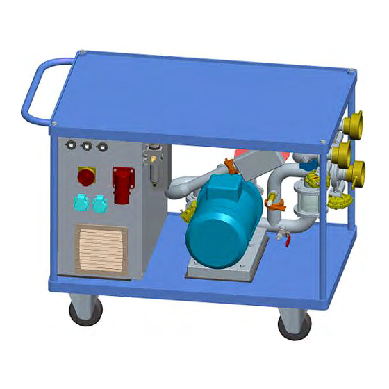
System description System description Construction of the gauging unit Schematic structure Vent valve Valve Y3 Valve Y1 OUT1 Sight glass Level sensor Pump OUT2 Valve Y4 Bypass Valve Y2 Instruction Manual PETRO 3003 VOLUTANK Gauging unit BA 140918... -
Page 13: Technical Data
System description Technical Data Electrical data Power supply AC 400 V 50 Hz max. 4 kVA Backup fuse Line cut-out 3x16 A (characteristic C) A universal residual-current circuit-breaker is recommended. The leakage current can exceed 30 mA when the unit is switched on! Compressed air 6 bar to max. -
Page 14: Storage, Transport And Start Of Operation
Storage, transport and start of operation Storage, transport and start of operation Storage and transportation of the gauging unit The gauging unit may only be transported with suitable lifting gear capable of bearing its weight. Gross weight as specified on type plate. Crane transport is not permitted. Do not allow the wheels on the gauging unit to bear the weight during stor- age and transportation. - Page 15 Storage, transport and start of operation The water still remaining in the pipes can be discharged via the ball valve on the gauging unit. Open the ball valve to drain the residual water. Ball valve closed Ball valve open NOTE: It can take some time to drain the unit.
-
Page 16: Putting The Gauging Unit Into Operation
Storage, transport and start of operation Putting the gauging unit into opera- tion Always check the gauging unit for damage before putting it into operation. Take measures to prevent the gauging unit from rolling away. Two castors are fitted with brakes which can be applied for this purpose. 4.3.1 Requirements The following requirements must be met in order to be able to use the gaug-... - Page 17 Storage, transport and start of operation ● Gauing into an external tank: The gauging process can only be completed successfully if the contents are pumped into another chamber or into an external tank because the contents need to be pumped back into the original chamber to calculate the pipe volume! In this case, before reaching the minimum dipstick height, the hose must be switched to a tank from which the contents can be pumped out again.
-
Page 18: Required Vehicle Version
Storage, transport and start of operation Windows XP: Control Panel Power Options Under no circumstances should the PC be locked, be switched to Hibernate state or the user changed during operation. The PC should always be operated with power plugged in. 4.3.1.1 Required vehicle version The gauging unit and the applicable software can be used from vehicle ver-... -
Page 19: Gauging Positions And Setting For Logical I/Os
Storage, transport and start of operation 4.3.1.3 Gauging positions and setting for logical I/Os The gauging unit must be connected differently (right/left) and certain logical outputs will also need to be connected depending on the design of the vehi- cle. Left-left design (left fill | left discharge): Left control (log. - Page 20 Storage, transport and start of operation Left-left-right design (left fill/discharge | right discharge): Left control (log. 14) Right control (log. 20) Direct outlet group valve (log. 9) API manually open/close Instruction Manual PETRO 3003 VOLUTANK Gauging unit BA 140918...
- Page 21 Storage, transport and start of operation Left-right design (left fill | right discharge): Left control (log. 14) Right control (log. 20) Direct outlet group valve (log. 9) Through valve manually open/close Instruction Manual PETRO 3003 VOLUTANK Gauging unit BA 140918...
-
Page 22: Installing The Pc Software
Storage, transport and start of operation 4.3.2 Installing the PC software The PC must be disconnected from all other networks before the gauging software is installed. System requirements for laptops or minimum configuration for laptops: ● Free hard disk space (min. 10 MB) ●... - Page 23 Storage, transport and start of operation Instruction Manual PETRO 3003 VOLUTANK Gauging unit BA 140918...
- Page 24 Storage, transport and start of operation Instruction Manual PETRO 3003 VOLUTANK Gauging unit BA 140918...
-
Page 25: Configuring The Ip Address
Storage, transport and start of operation 4.3.2.1 Configuring the IP address Windows XP Press "Start" to open the "Control Panel". If a list is displayed here, it is advisable to switch to "Classic View". Now se- lect "Network and Internet Connections". Instruction Manual PETRO 3003 VOLUTANK Gauging unit BA 140918... - Page 26 Storage, transport and start of operation Click on "Network Connections" in the next dialog box. Select "LAN Connection" (Ethernet cable connected directly) or "LAN Con- nection 2" (Ethernet cable connected with USB Ethernet adapter) from the list of all the network connections and right-click on "Properties". A list of properties will be displayed.
- Page 27 Storage, transport and start of operation The following settings apply: Instruction Manual PETRO 3003 VOLUTANK Gauging unit BA 140918...
-
Page 28: Windows 7
Storage, transport and start of operation Windows 7 Press the Windows key on the keyboard or the Windows icon on the task bar to open the Windows menu and the "Control Panel". The "Control Panel" dialog box contains setting options for the computer. Se- lect "Network and Internet". - Page 29 Storage, transport and start of operation Click on "Network Status and Tasks" in this dialog box. A static IP address is allocated via "Change Adapter Settings". Instruction Manual PETRO 3003 VOLUTANK Gauging unit BA 140918...
- Page 30 Storage, transport and start of operation Now right-click on "LAN Connection" (Ethernet cable connected directly) or "LAN Connection 2" (Ethernet cable connected with USB Ethernet adapter) and select "Properties". Go to "Internet Protocol Version 4 (TCP/IPv4)", open "Properties" and assign the static IP address "192.168.55.10".
-
Page 31: Connections
Storage, transport and start of operation 4.3.3 Connections 4.3.3.1 Power supply A 16 A fuse (characteristic C) should be used as a backup fuse. A universal residual-current circuit-breaker is recommended. Residual- current circuit-breakers with a release current of 30 mA can trip when the unit is switched on. -
Page 32: Network Connections
Storage, transport and start of operation 4.3.3.3 Network connections Unscrew the cap from the network socket and connect the network cable. It doesn’t matter which connector is used. Instruction Manual PETRO 3003 VOLUTANK Gauging unit BA 140918... -
Page 33: Hose Connections
Storage, transport and start of operation 4.3.3.4 Hose connections Female coupling Male coupling Bring the couplings together, fitting the ridges on the male coupling in the notches on the female coupling. Bring the jaw of the female coupling to the start of the moulding (male coupling) and tighten (by hand only). -
Page 34: Operation Of The Gauging Unit
Operation of the gauging unit Operation of the gauging unit “ALI menu” on System 3003 The "ALI menu" application starts automatically when the "gauging unit" PC software is started on the System3003 connected via the network: The “ “ button displays the diagnostic page for the dipstick interface: The dipstick readings can be checked here. -
Page 35: Hose Connection From The Vehicle To "In" On The Gauging Unit
Operation of the gauging unit Hose connection from the vehicle to “IN” on the gauging unit The connection hose to the vehicle should be as short as possible so as to prevent water from stopping in the hose during the gauging process and falsifying the reading (pipe volume and dead volume). - Page 36 Operation of the gauging unit The other functions are categorised under tab headings: Instruction Manual PETRO 3003 VOLUTANK Gauging unit BA 140918...
-
Page 37: Configuration" Tab
Operation of the gauging unit 5.3.1 “Configuration” tab Global settings are configured in this tab. They apply to each gauging process and are saved. Zoom: The program can be scaled down to as little as 60% so that the display is correct on monitors with a lower resolution. This change will on- ly take effect after the program is restarted. -
Page 38: System 3003" Tab
Operation of the gauging unit The MID correction factor is also entered. Hereby the measured value of the MID can be adjusted in percent. The value "1.0" corresponds to 100 %. CAUTION! If the hose connecting the vehicle and the “IN” is replaced, it is always necessary to recalculate the volume and change it in the configuration. - Page 39 Operation of the gauging unit The length configured in System 3003 and the current status are dis- played for each dipstick. The floating gauge height measurements are shown in the "Filling levels" section. The filling level percentage relates to the total length of the dipstick. Instruction Manual PETRO 3003 VOLUTANK Gauging unit BA 140918...
-
Page 40: Manual Control" Tab
Operation of the gauging unit 5.3.3 “Manual control“ tab The “Manual control” tab has the following functions: Test the gauging unit hardware, Transfer pumping operations when capacity measurement is not in progress, Pumping is no System 3003 is connected. The valves necessary for gauging on the vehicle can be controlled as can the hardware of the gauging unit itself. -
Page 41: Special Function "Pump Over
Operation of the gauging unit 5.3.4 Special function “pump over“ The special function automatically controls the required valves and the pump: Vehicle chambers and external tanks can be connected at the respective connection (IN, OUT1, OUT2). When vehicle chambers are connected, a check takes place during the filling process to determine whether the float gauge is moving and otherwise the pump is stopped. -
Page 42: Gauge" Tab
Operation of the gauging unit 5.3.5 “Gauge” tab The actual gauging process takes place in this view. 5.3.5.1 “Settings” The preparations for the gauging process are made here. The names of the gauging files (Geometrie, Rohrvolumen- and Stützpunktdatei - geometry, pipe volume and support point file) must be entered. -
Page 43: Overview
Operation of the gauging unit 5.3.5.2 “Overview” The "Overview" screen displays the current levels of all the dipsticks con- nected. The data below indicate the present states and values of the gauging unit. The following functions are available: See section 5.3.4. Instruction Manual PETRO 3003 VOLUTANK Gauging unit BA 140918... - Page 44 Operation of the gauging unit At the start of the gauging process a check is done to make sure that there is no file existing with the same name. If one is existing the user has to confirm if the file should be overwritten: Press "OK"...
- Page 45 Operation of the gauging unit The gauging process will resume when the dialog box is acknowledged. If the angle values are outside the tolerance (±0.1), the message shown below will be displayed. In this case the prompt must be cleared by pressing "OK"...
- Page 46 Operation of the gauging unit The automatic gauging process is started after start-up. The measurements are entered in the graph on the right during the gaug- ing process: Instruction Manual PETRO 3003 VOLUTANK Gauging unit BA 140918...
-
Page 47: Stopping The Gauging Process
Operation of the gauging unit 5.3.5.3 Stopping the gauging process Press the pause button to halt the gauging process. The "Change hoses" function can be used during the interval (cf. section 5.3.5.2). CAUTION! The pause function is only available until the minimum dipstick level is reached. -
Page 48: General Procedure During The Gauging Process
Operation of the gauging unit 5.3.5.4 General procedure during the gauging process Dead volume calculation: The vehicle chamber is emptied down to the minimum level (this level is configured in the gauging unit (cf. "Settings": min. height [mm])). The process of measuring the dead volume plus the pipe volume is then started. -
Page 49: Servicing, Maintenance And Cleaning
Servicing, maintenance and cleaning Servicing, maintenance and cleaning CAUTION! ● Servicing, maintenance, repair and cleaning work may only be carried out with the unit switched off. The unit must be switched off at the mains and measures taken to prevent it from being switched on accidentally. ●... -
Page 50: Servicing And Replacing The Impeller
Servicing, maintenance and cleaning Servicing and replacing the impeller Follow the instructions below to service or replace the impeller: ● Drain the unit completely, referring to the relevant instructions in section 4.2. ● Switch the unit off by turning the main switch, and take measures to prevent the unit from being switched back on. -
Page 51: Troubleshooting
Servicing, maintenance and cleaning Troubleshooting Malfunction Possible cause Remedy No power supply to Mains cable is not plugged in or is defective Connect gauging unit operational mains cable Mains switch is off Switch on at the mains ... -
Page 52: Replacement Parts
Servicing, maintenance and cleaning Replacement parts Use only original spare parts supplied by BARTEC BENKE GmbH Part Order no. Impeller for pump IP20 378723 Seal assembly for disk valve On request Low-level indicator sensor U8911672922 366588 Sound absorber AN15-C08 205860... -
Page 53: Ce Mark
CE mark CE mark The gauging unit is built in conformity with the current EU directives and car- ries the CE mark of conformity. The enclosed declaration of conformity shall be rendered invalid if the gaug- ing unit is converted or modified without our consent. Disassembly and disposal ●... -
Page 54: Appendix
Appendix Hardware checklist Checkpoint Comments (Signature) 1. Visual check Check for obvious signs of damage Check low-level indicator fitting 2. Check connection cable Check cable for obvious signs of damage Check protective conductor terminals 3. Technical safety test Measure PE resistance R Resistance:________________________________ ohm Measure leakage and touch current I Leakage current: _____________________________ mA... - Page 55 9. Test unit with water Pumping IN to OUT OK Pumping OUT to IN OK Low-level indicator OK 10. Drain unit Unit empty Instruction Manual PETRO 3003 VOLUTANK Gauging unit BA 140918...
-
Page 56: Wiring Diagram
Wiring diagram Instruction Manual PETRO 3003 VOLUTANK Gauging unit BA 140918... - Page 57 Instruction Manual PETRO 3003 VOLUTANK Gauging unit BA 140918...
- Page 58 Instruction Manual PETRO 3003 VOLUTANK Gauging unit BA 140918...
- Page 59 Instruction Manual PETRO 3003 VOLUTANK Gauging unit BA 140918...
- Page 60 Instruction Manual PETRO 3003 VOLUTANK Gauging unit BA 140918...
- Page 61 Instruction Manual PETRO 3003 VOLUTANK Gauging unit BA 140918...
- Page 62 Instruction Manual PETRO 3003 VOLUTANK Gauging unit BA 140918...
- Page 63 Instruction Manual PETRO 3003 VOLUTANK Gauging unit BA 140918...
- Page 64 Instruction Manual PETRO 3003 VOLUTANK Gauging unit BA 140918...
- Page 65 Instruction Manual PETRO 3003 VOLUTANK Gauging unit BA 140918...
- Page 66 Instruction Manual PETRO 3003 VOLUTANK Gauging unit BA 140918...
- Page 67 Instruction Manual PETRO 3003 VOLUTANK Gauging unit BA 140918...
- Page 68 Instruction Manual PETRO 3003 VOLUTANK Gauging unit BA 140918...
Need help?
Do you have a question about the A Series and is the answer not in the manual?
Questions and answers