Table of Contents
Advertisement
Advertisement
Table of Contents

Related Manuals for BARTEC BENKE CFPP-4.2


Summary of Contents for BARTEC BENKE CFPP-4.2
- Page 1 CFPP Process Analyzer CFPP-4.2 Operating Instructions 395778MDHEN A 03/2016...
- Page 2 These operating instructions are subject to copyright laws. This document may not be reproduced or transmitted, neither whole nor in parts, by any electronic, mechanical or other means, without prior written permission from BARTEC BENKE GmbH. Nor is production of the entire instrument or individual components permissible on the basis of...
-
Page 3: Table Of Contents
Potential Dangers and Risks ................18 In Case of an Accident or Emergency .............. 22 Introduction ..................23 The CFPP Process Analyzer CFPP-4.2 ............24 Significance of the Cold Filter Plugging Point ..........25 Measuring Principle ..................25 Technical Data .................. 27 Analyzer Description ................ - Page 4 10.10 Changing the battery of the box PC ..............79 10.11 Checking for product and emptying vacuum tank ........... 81 10.12 Removing the Measuring Cell ................. 82 10.13 Cleaning the Test Filter..................86 10.14 Checking Liquid Level in the Sample Container ..........89 CFPP Process Analyzer CFPP-4.2 03/2016...
- Page 5 Adjusting the Liquid Level in the Sample Container ......93 10.15 Reinstalling the Measuring Cell ................ 94 10.16 Remove the cover of the measuring cell housing ..........97 10.17 Install the cover on the measuring cell housing ..........99 11 Troubleshooting ................101 03/2016 CFPP Process Analyzer CFPP-4.2...
- Page 6 Contents CFPP Process Analyzer CFPP-4.2 03/2016...
-
Page 7: General
General 1 General 03/2016 CFPP Process Analyzer CFPP-4.2... -
Page 8: About This Document
If you have little or no experience working with such instruments, we recommend that you get advice from experienced persons or take part in a training course by BARTEC BENKE before using the instrument. These operating instructions must always be kept with the analyzer and must be accessible at any time. -
Page 9: Safety
Safety 2 Safety 03/2016 CFPP Process Analyzer CFPP-4.2... -
Page 10: General
Intended Use The CFPP Process Analyzer CFPP-4.2 is designed for determining in a fully automated process the temperature limit value for the filterability of liquid petrochemical products. A sample stream and a calibration stream (optional) can be connected to the analyzer, which operates online. -
Page 11: Safety Symbols And Signal Words
The signal words DANGER!, WARNING! and CAUTION! are used with triangular symbols which state type hazard, example: General hazard Dangerous electric current Potentially explosive atmosphere Hazardous substances Coldness Hot surfaces The following symbol is used with the signal word ATTENTION!: 03/2016 CFPP Process Analyzer CFPP-4.2... -
Page 12: Explosion Protection
The maximum surface temperature of the analyzer is <135°C. Gb: The device ensures a high degree of safety. It can be used in zone 1 and in zone 2. A potentially explosive atmosphere may occasionally occur. CFPP Process Analyzer CFPP-4.2 03/2016... - Page 13 T1 to T6 (in accordance with IEC 60079-4). The device has been designed for use with gases and vapors of temperature class: T4: 135 °C < ignition temperature < 200 °C 03/2016 CFPP Process Analyzer CFPP-4.2...
-
Page 14: Types Of Protection And Certificates
Intrinsic safety “i” Intrinsically safe circuits are circuits in which no spark or thermic effect can ignite an explosive atmosphere of the subgroups IIA, IIB or IIC. CFPP Process Analyzer CFPP-4.2 03/2016... - Page 15 For this reason the device does not require an assessment as an electrical device according to ATEX. The conformity assessment process has been checked by a notified body and has been approved via a statement of conformity. 03/2016 CFPP Process Analyzer CFPP-4.2...
-
Page 16: Ensuring And Maintaining Explosion Protection
It is not permissible to make any technical modifications to the analyzer • without written authorization from BARTEC BENKE. Any unauthorized modification can impair the safety of the analyzer and lead to accidents. Use only spare parts supplied by BARTEC BENKE. - Page 17 21 Warning label “Fluids under 10 Locks of control box pressure” 11 Warning label “Opening the 22 Mandatory-sign “Wear protective housing” goggles” 12 Door of control box 23 Mandatory-sign “Wear protective 13 Rear cover of Chiller for Liquids gloves” 03/2016 CFPP Process Analyzer CFPP-4.2...
- Page 18 (e) in closed condition only. Therefore keep the cover of the signal junction box closed with all fastening bolts during normal operation. CFPP Process Analyzer CFPP-4.2 03/2016...
-
Page 19: Personnel
10.4. The protective devices must never be removed, bypassed or made unusable in any way. The warning labels must be kept easily readable. Spare warning labels are available from BARTEC BENKE. Personnel Personnel working with the analyzer must be trained, authorized and instructed, particularly with respect to possible hazards. -
Page 20: Personal Protective Equipment
Work on electrical equipment must be carried out by qualified personnel according to chapter 2.6. Do not remove or disable any protective devices. CFPP Process Analyzer CFPP-4.2 03/2016... - Page 21 Never clean plastic parts (such as the touchscreen) with a dry cloth, but always use a damp cloth to avoid static electricity discharge and sparks. Do not remove or disable any protective devices. 03/2016 CFPP Process Analyzer CFPP-4.2...
- Page 22 Hot components! Risk of burning! FOR THIS REASON: Before touching a component in case of malfunction, check that the component has cooled down sufficiently. Wear protective gloves. Do not remove or disable any protective devices. CFPP Process Analyzer CFPP-4.2 03/2016...
- Page 23 Resulting sparks can ignite potentially explosive atmospheres. FOR THIS REASON: Always clean plastic surfaces with a moist cloth. Note: Detailed information for a safe use of the Chiller for Liquids you find in the manual for the Chiller for Liquids. 03/2016 CFPP Process Analyzer CFPP-4.2...
-
Page 24: In Case Of An Accident Or Emergency
Switching off the analyzer by disconnecting it from the power supply can lead to lost data. FOR THIS REASON: Only use this procedure to switch off the analyzer in an emergency. • Suitable fire extinguishing agent: Fire extinguisher with ABC powder. CFPP Process Analyzer CFPP-4.2 03/2016... -
Page 25: Introduction
Introduction 3 Introduction 03/2016 CFPP Process Analyzer CFPP-4.2... -
Page 26: The Cfpp Process Analyzer Cfpp-4.2
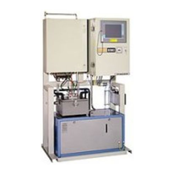
The CFPP Process Analyzer CFPP-4.2 Fig. 3.1: The CFPP Process Analyzer CFPP-4.2 The analyzer CFPP-4.2 measures the cold filter plugging point (CFPP, temperature limit value for filterability) online in a fully automated process. The measuring range is from - 35°C to +10°C. A sample stream and a calibration stream can be connected (additional components required). -
Page 27: Significance Of The Cold Filter Plugging Point
The cold filter plugging point (CFPP) of a petrochemical product is an important indicator for the behavior of that product at low temperatures. The analyzer CFPP-4.2 is designed for monitoring and controlling the production process and the composition of blends such as diesel fuels and heating oils. - Page 28 Introduction CFPP Process Analyzer CFPP-4.2 03/2016...
-
Page 29: Technical Data
Technical Data 4 Technical Data 03/2016 CFPP Process Analyzer CFPP-4.2... - Page 30 8 Nm /h (purging phase) approx. 2.3 Nm³/h (normal operation) approx. 1.7 Nm³/h in operation (in addition) Option Vortex Quality According to ISO 8573-1: class 2 or better Primary pressure 3 bar ... 7 bar CFPP Process Analyzer CFPP-4.2 03/2016...
- Page 31 3. identification of a validation cycle Options: 4. alarm: measuring range exceeded 5. warning, a (minor) error has occurred Digital inputs 1. reset 2. request for validation cycle Options: 1. summer product / winter product 03/2016 CFPP Process Analyzer CFPP-4.2...
- Page 32 * If a vortex cooler is used for the control box, make sure that at the very most drip water can hit the analyzer in compliance with EN 60529. Note: The analyzer is subject to continuous improvements, so that technical changes are possible. CFPP Process Analyzer CFPP-4.2 03/2016...
-
Page 33: Analyzer Description
Analyzer Description 5 Analyzer Description 03/2016 CFPP Process Analyzer CFPP-4.2... -
Page 34: Overview And Operating Elements
(15) cool the sample. The measuring cell housing is pressurized together with the control box (8). The control box contains the analyzer control unit and the control unit for the cooling system. CFPP Process Analyzer CFPP-4.2 03/2016... - Page 35 By means of the key switch (6) ("bypass switch"), you can activate or deactivate the explosion protection (overpressure monitoring) for the pressurized control box (8) and the measuring cell housing (15). 03/2016 CFPP Process Analyzer CFPP-4.2...
-
Page 36: Type Plates
On the type plates, you will find the most important information on explosion protection and safe operation of the analyzer as well as the analyzer’s serial number. Make sure that the type plate is always kept easily readable. CFPP Process Analyzer CFPP-4.2 03/2016... -
Page 37: Analyzer Components
Air service unit for pressurized Metering valve injector housings Pressure gauge for backflow 10 Metering valve measuring cell detection 11 Vacuum injector Pipe heater 12 Vacuum pressure switch Flow controller 13 Vacuum pressure controller Magnetic valves 03/2016 CFPP Process Analyzer CFPP-4.2... - Page 38 The pressure switch for backflow detection (2) allows to determine whether the product, after being sucked through the test filter, flows back into the sample container. The Pressure gauge for backflow detection (4) allows you to monitor the pressure visually. CFPP Process Analyzer CFPP-4.2 03/2016...
-
Page 39: Measuring Cell
The liquid sensor (1) detects the sample that is sucked through the test filter. Instrument air from the decondensation ring (3) prevents condensation or ice on the cold surface of the measuring cell. 03/2016 CFPP Process Analyzer CFPP-4.2... -
Page 40: Control Box
Measuring transmitters and amplifiers, switching amplifiers • Cooler for the housing (optional) • Note: The description given here refers to the standard system. The construction of your control box may be different from the one described here. CFPP Process Analyzer CFPP-4.2 03/2016... -
Page 41: Sample Conditioning System (Optional)
Control valve for cooling water (6) • • Shut-off valves for cooling water (7) Note: The description given here refers to the standard system. For a detailed description of your sample conditioning system, please refer to the technical documents supplied. 03/2016 CFPP Process Analyzer CFPP-4.2... -
Page 42: Further Options
The liquid chiller supplies cold cooling medium for the heat exchanger in the sample conditioning system (see Fig. above, pos. 8) and for any additional heat exchangers that may be installed. For more detailed information on the explosion-proof chiller for liquids, please refer to the supplied operation manual. CFPP Process Analyzer CFPP-4.2 03/2016... -
Page 43: Transport, Packaging And Storage
Transport, Packaging and Storage 6 Transport, Packaging and Storage 03/2016 CFPP Process Analyzer CFPP-4.2... -
Page 44: Transport
Use suitable lifting equipment. Keep a safe distance when lifting the analyzer, because it may swivel out to one side. Do not lift the analyzer higher than necessary. Do not stand below the analyzer. Keep a safe distance. CFPP Process Analyzer CFPP-4.2 03/2016... -
Page 45: Delivery
German Federal Society for Wood, Pallet and Export Packaging. Remove the packing on the analyzer carefully at the installation site and dispose of it in an environmentally sound manner. Pay attention to the notes on the packing material. 03/2016 CFPP Process Analyzer CFPP-4.2... - Page 46 Transport, Packaging and Storage CFPP Process Analyzer CFPP-4.2 03/2016...
-
Page 47: Installation And Disassembly
Installation and Disassembly 7 Installation and Disassembly 03/2016 CFPP Process Analyzer CFPP-4.2... -
Page 48: Installation
Observe the regulations for mounting the pipe connections. Please refer to the supplied manufacturer’s documentation. Make sure that the minimum bending radius of the pipes is observed. Note: Your sample conditioning system may be different from the one described here. If in doubt, please contact BARTEC BENKE. CFPP Process Analyzer CFPP-4.2 03/2016... -
Page 49: Securing The Analyzer
Adjust the analyzer vertically and horizontally and secure it to the floor with four fastening screws M 12 (not included in delivery). For the dimensions of the fixing holes, please refer to the supplied layout drawing. 03/2016 CFPP Process Analyzer CFPP-4.2... -
Page 50: Tubing Connections
The shut-off valves must be installed near the analyzer and must be easily accessible. They must be clearly marked so that they can be identified as belonging to the analyzer and to the substances they carry. CFPP Process Analyzer CFPP-4.2 03/2016... -
Page 51: Electrical Connections
Switch off the power supply and secure it, so that it cannot be switched on accidentally. All work on the electrical system must be carried out by personnel qualified for electrical installation and explosion protection. Do not remove or disable any protective devices. 03/2016 CFPP Process Analyzer CFPP-4.2... - Page 52 Lock the power supply box by using a double-bit key. Secure the cover of the signal • junction box with the fastening screws. The electrical connections are complete. The analyzer is now ready to be put into operation (see chapter 8). CFPP Process Analyzer CFPP-4.2 03/2016...
-
Page 53: Disassembly
Disconnect all cable connections and pull them out of the junction box. • Unscrew the equipotential bonding cable at the frame. Close the junction box. • The analyzer is now disconnected from the power supply. 03/2016 CFPP Process Analyzer CFPP-4.2... -
Page 54: Removing Tubing Connections
The pipe connections are now disconnected and the analyzer is ready to be disassembled. Disposal Make sure that the analyzer is recycled and disposed of in an environmentally sound manner. Observe the applicable local regulations. CFPP Process Analyzer CFPP-4.2 03/2016... -
Page 55: Initial Operation
Initial Operation 8 Initial Operation 03/2016 CFPP Process Analyzer CFPP-4.2... -
Page 56: Putting The Analyzer Into Operation
Initial Operation Note: We recommend to have the system put into operation by BARTEC BENKE service personnel, and to have your operators and maintenance staff instructed and trained by BARTEC BENKE. Putting the Analyzer into Operation Note: Before you put the analyzer into operation, you have to refill the Chiller for Liquids with coolant. - Page 57 The pipe that will be opened contains pressurized liquids. CAUTION! Pressurized liquid! Risk of injury! FOR THIS REASON: Close the product feed line before starting work. Wear your personal protective equipment, at least wear protective goggles and protective gloves. 03/2016 CFPP Process Analyzer CFPP-4.2...
- Page 58 Product feed line on the analyzer Note: Your sample conditioning system may be different from the one described here. If in doubt, please contact BARTEC BENKE. Close the shut-off valve on the system side of the product feed line. •...
-
Page 59: Initial Operation Of The Sample Conditioning System (Optional)
Note: Your sample conditioning system may be different from the one described here. If in doubt, please contact BARTEC BENKE. To put the sample conditioning system into operation, proceed as follows: Make sure that the pressure and temperature in the product feed line correspond to •... - Page 60 (5) (see target value on the label). • If required, readjust the pressure with the pressure regulator (3) (see target value on the label). The sample conditioning system is now ready for operation. CFPP Process Analyzer CFPP-4.2 03/2016...
-
Page 61: Feeding In Product
Make sure that the parameters correspond to the values specified in the supplied • layout drawing and the technical data. Product pressure at inlet • Product flow rate • Product temperature • The analyzer is now supplied with product. 03/2016 CFPP Process Analyzer CFPP-4.2... -
Page 62: Connecting The Analyzer To Instrument Air Supply
Fig. 8.3: Open measuring unit enclosure Vacuum pressure gauge Air service unit for pressurized Pressure gauge for backflow housings detection Metering valve measuring cell Air service unit for injector and Vacuum pressure controller measuring cell CFPP Process Analyzer CFPP-4.2 03/2016... - Page 63 The air flow is important for the detection of the sample backflow. The precise adjusting of the air flow you have to do during the process step “Instrument testing” by considering the pressure gauge (2). 03/2016 CFPP Process Analyzer CFPP-4.2...
- Page 64 Initial Operation CFPP Process Analyzer CFPP-4.2 03/2016...
-
Page 65: Operation
Operation 9 Operation 03/2016 CFPP Process Analyzer CFPP-4.2... -
Page 66: Switching On The Analyzer
The control box and the measuring cell housing are purged with instrument air (loud noise). Fig. 9.1: Overpressure control display Touchscreen Overpressure control display The remaining purge time is displayed by the overpressure control system (2). • CFPP Process Analyzer CFPP-4.2 03/2016... -
Page 67: Operation
• Using the pen on the touchscreen, click on File in the menu. Click on Exit. • Click on Shutdown. • • Wait until the computer has shut down. 03/2016 CFPP Process Analyzer CFPP-4.2... -
Page 68: Switching Off In An Emergency
The analyzer is now switched off. CAUTION! Switching off the analyzer by disconnecting it from the power supply can lead to lost data. FOR THIS REASON: Only use this procedure to switch off the analyzer in an emergency. CFPP Process Analyzer CFPP-4.2 03/2016... -
Page 69: Maintenance
Maintenance 10 Maintenance 03/2016 CFPP Process Analyzer CFPP-4.2... -
Page 70: Safety During Maintenance
Warning! No explosion protection due to using incorrect spare parts! Some optional used spare parts are modified by BARTEC BENKE for a particular purpose. The use of non-modified original spare parts of the relative manufacturer can cause loss of explosion protection. -
Page 71: Measures After Maintenance
Change Lithium battery of PC (see chapter 10.10). Have the Chiller for Liquids serviced by cooling systems expert (check dryer and level of cooling agent, clean fins). Information therefor you find in the manual for the Chiller for Liquids. 03/2016 CFPP Process Analyzer CFPP-4.2... -
Page 72: Checking The Protective Devices
21 Warning label “Fluids under 10 Locks of control box pressure” 11 Warning label “Opening the 22 Mandatory-sign “Wear protective housing” goggles” 12 Door of control box 23 Mandatory-sign “Wear protective 13 Rear cover of Chiller for Liquids gloves” CFPP Process Analyzer CFPP-4.2 03/2016... - Page 73 Housing of undamaged Chiller for Liquids (9) no open bore holes or mounting cut-outs (except ventilation holes) all covers (8, 9 and 13) are closed tightly Spare warning labels are available from BARTEC BENKE. 03/2016 CFPP Process Analyzer CFPP-4.2...
-
Page 74: General Visual Inspection
Checks Remedy Error messages from the PACS process see software manual software Leakages remove immediately Ice forming on measuring cell ensure instrument air supply according to specification (see chapter 4) CFPP Process Analyzer CFPP-4.2 03/2016... -
Page 75: Visual Inspection Inside Measuring Unit Enclosure
Fig. 10.2: Visual Inspection Inside Measuring unit enclosure Vacuum pressure gauge Air service unit for pressurized Metering valve injector housings Pressure gauge for backflow Metering valve measuring cell detection Vacuum pressure controller Flow controller Air service unit for injector and measuring cell 03/2016 CFPP Process Analyzer CFPP-4.2... - Page 76 (2). Check measuring cell pressure (3) for backflow Adjust measuring cell recognition (during process step “Instrument Testing”). pressure at needle valve (7). Leakages Remove Close the measuring unit enclosure. The visual inspection is finished. CFPP Process Analyzer CFPP-4.2 03/2016...
-
Page 77: Checking The Residual-Current Device (Rcd)
Measures after the RCD has triggered 1. If the RCD has triggered, switch it back on. 2. Close the control box and secure the connections with safety bolts. Explosion protection 3. Turn the key switch back to the position. 03/2016 CFPP Process Analyzer CFPP-4.2... -
Page 78: Measures In Case Of Troubles
If the above mentioned causes are impossible or if the RCD malfunctions replace the RCD. A new RCD is available at BARTEC BENKE. If the RCD is damaged it may not be repaired. -
Page 79: Checking The Test Filter
If dirt particles are visible, clean the test filter (see chapter 10.13). Wait for the process step Hot Flushing. • • Watch the upper part of the measuring cell. A strong product stream should be visible coming from the pipe connection (1). 03/2016 CFPP Process Analyzer CFPP-4.2... -
Page 80: Cleaning The Touchscreen
Apply some cleaning agent to the cloth, not to the touchscreen. • Clean the touchscreen with the cleaning cloth. The touchscreen has been cleaned. You can now switch the analyzer back on (see chapter 9). CFPP Process Analyzer CFPP-4.2 03/2016... -
Page 81: Changing The Battery Of The Box Pc
Danger of explosion by using unsuitable batteries in potentially explosive atmosphere! Unsuitable batteries can ignite potentially explosive atmosphere by overheating in the event of an error! FOR THIS REASON: For replacement use only batteries from BARTEC BENKE. 03/2016 CFPP Process Analyzer CFPP-4.2... - Page 82 Maintenance CAUTION! Unsuitable batteries can damage the box PC. FOR THIS REASON: For replacement use only batteries from BARTEC BENKE. Note: Information for changing the battery you find in the provided manual for the box PC. • Change the battery of the box PC.
-
Page 83: Checking For Product And Emptying Vacuum Tank
The vacuum tank is located on the back side of the analyzer. At the bottom side of the vacuum tank a drain with blind cap (2) is installed. • Keep a drain bottle (at least 200 ml) for product ready. 03/2016 CFPP Process Analyzer CFPP-4.2... -
Page 84: Removing The Measuring Cell
10.12 Removing the Measuring Cell For cleaning the test filter, for checking the liquid level in the sample container and for changing the cover of the measuring cell housing you must remove the measuring cell. CFPP Process Analyzer CFPP-4.2 03/2016... - Page 85 Connectors for the liquid sensor 11 Decondensation ring Screws decondensation ring 12 Drain pipe Quick-release coupling of the red pipe • Pull off the connector (4) for the temperature sensors and the liquid sensor (5). 03/2016 CFPP Process Analyzer CFPP-4.2...
- Page 86 Fig. 10.6: Loosen screw connections Loosen union nut (10) of the sample temperature sensors, while holding the assembly • in position with a wrench (see figure Fig. 10.6). CFPP Process Analyzer CFPP-4.2 03/2016...
- Page 87 Place a clean cloth on the surface where the measuring cell will be put down. • Lift out the measuring cell in an upright position, without tilting it. • • Put down the measuring cell in an upright position. 03/2016 CFPP Process Analyzer CFPP-4.2...
-
Page 88: Cleaning The Test Filter
Remove the measuring cell (see chapter 10.10). • Fig. 10.7: Measuring cell • Wait until the cooling jacket (1) has warmed up to > 0 °C (no ice visible). CFPP Process Analyzer CFPP-4.2 03/2016... - Page 89 Fig. 10.8: Disassembling the sample container Glass body Red plastic ring • Holding the measuring cell upright, remove the sample container. To do this, hold the red plastic ring (5), not the glass body (4). • 03/2016 CFPP Process Analyzer CFPP-4.2...
- Page 90 Test filter • Remove the test filter (9). • Clean the test filter and the sample container with a suitable detergent or solvent. Disassembly and cleaning are now finished. You can now reassemble the test filter. CFPP Process Analyzer CFPP-4.2 03/2016...
-
Page 91: Checking Liquid Level In The Sample Container
You can combine this task with the task “Cleaning the Test Filter” (see chapter 10.13). 10.14.1 Checking the Liquid Level in the Sample Container The analyzer must be operating. • Drip down Wait until the analyzer has finished the process step • 03/2016 CFPP Process Analyzer CFPP-4.2... - Page 92 Wear your personal protective equipment, at least wear protective goggles and protective gloves suitable for the respective substances. Make sure there is sufficient ventilation. Immediately clean up spilled chemicals. CFPP Process Analyzer CFPP-4.2 03/2016...
- Page 93 Fig. 10.13: Disassembling the sample container Glass body Red plastic ring • Holding the measuring cell upright, remove the sample container. To do this, hold the red plastic ring (5), not the glass body (4). • 03/2016 CFPP Process Analyzer CFPP-4.2...
- Page 94 Red plastic ring Apply a small amount of mounting paste to the O-ring (10) of the sample container. • • To mount the sample container, hold the red plastic ring (5), not the glass body (4). CFPP Process Analyzer CFPP-4.2 03/2016...
-
Page 95: Adjusting The Liquid Level In The Sample Container
Fig. 10.16: Lock nut of the outlet pipe Outlet pipe Lock nut Loosen the lock nut (2) of the outlet pipe (1) with needle-nosed pliers while holding • the outlet pipe to keep it in position. 03/2016 CFPP Process Analyzer CFPP-4.2... -
Page 96: Reinstalling The Measuring Cell
10.15 Reinstalling the Measuring Cell CAUTION! The transparent plastic of the measuring cell is not alcohol-resistant, it will be damaged by contact with alcohol. FOR THIS REASON: Do not clean the transparent plastic parts with alcohol. CFPP Process Analyzer CFPP-4.2 03/2016... - Page 97 Quick-release coupling of the red pipe The correct mounting position can be checked by the position of the drain pipe (12). Slowly lower the measuring cell. • • Replace the fixing screws (9) and tighten them hand-tight. 03/2016 CFPP Process Analyzer CFPP-4.2...
- Page 98 Slightly tighten the corresponding union nut while holding the assembly in position with a wrench. • Push the connectors for the temperature sensors and for the liquid sensor (5) into the corresponding sockets with the same color. CFPP Process Analyzer CFPP-4.2 03/2016...
-
Page 99: Remove The Cover Of The Measuring Cell Housing
5 Measuring cell housing This is how to remove the cover: Remove the measuring cell (see page 82). • To remove the cover you have to loose the screw connections (2) of the coolant lines. 03/2016 CFPP Process Analyzer CFPP-4.2... - Page 100 • Lift the cover (3) gently. Separate the connecting cable from the measuring cell housing by disconnecting the connector at the bottom of the measuring cell housing. • Remove the cover in complete. CFPP Process Analyzer CFPP-4.2 03/2016...
-
Page 101: Install The Cover On The Measuring Cell Housing
Risk of skin damage on direct contact. FOR THIS REASON: Wear protective gloves and protective goggles. Close the screw connections (2) of the coolant lines. To this remove the blind plugs. • Reinstall the measuring cell (see page 94). • 03/2016 CFPP Process Analyzer CFPP-4.2... - Page 102 Maintenance CFPP Process Analyzer CFPP-4.2 03/2016...
-
Page 103: Troubleshooting
Troubleshooting 11 Troubleshooting 03/2016 CFPP Process Analyzer CFPP-4.2... - Page 104 Unsuitable parameter settings Adjust the parameters (see software manual). Cable connection to the Remove the cause of the analyzer is interrupted malfunction. Measuring value output Sudden significant changes in signals an unusual or product properties CFPP Process Analyzer CFPP-4.2 03/2016...
- Page 105 (see chapter 4) No product flow in the Malfunction in the sample Remove the cause of the analyzer conditioning system malfunction. Make sure that the product is conditioned as specified in the technical data. 03/2016 CFPP Process Analyzer CFPP-4.2...
- Page 106 Thermal fuse of peltier Find and remove the cause elements has blown. of the malfunction. Temperature of coolant is not Please refer to the manual deep enough. Chiller for Liquids. CFPP Process Analyzer CFPP-4.2 03/2016...
- Page 107 Troubleshooting 03/2016 CFPP Process Analyzer CFPP-4.2...
Need help?
Do you have a question about the CFPP-4.2 and is the answer not in the manual?
Questions and answers