Table of Contents
Advertisement
Advertisement
Table of Contents

Subscribe to Our Youtube Channel
Related Manuals for PCE Instruments PCE-ITM 20


Summary of Contents for PCE Instruments PCE-ITM 20
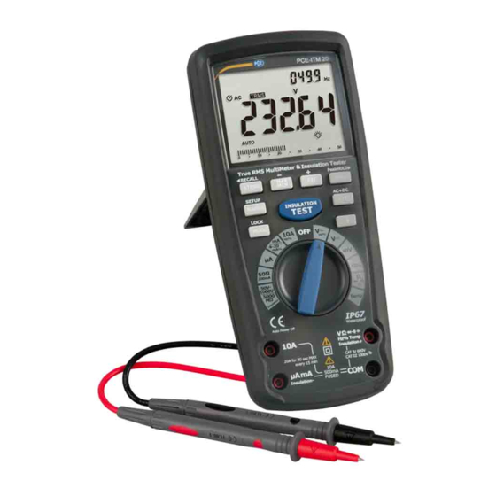
- Page 1 User Manual Isolation Meter PCE-ITM 20 PCE-ITM 20 User manuals in various languages (français, italiano, español, português, nederlands, türk, polski, русский, 中文) can be found by using our product search on: www.pce-instruments.com Last change: 3 May 2019 v1.0 © PCE Instruments...
-
Page 2: Table Of Contents
3.18 Relative Mode .........................17 3.19 Display Backlight ......................17 3.20 HOLD ..........................17 3.21 PEAK HOLD ........................17 3.22 Data Record (Store/Recall) .....................17 3.23 Parameter setting up (SET) .....................18 3.24 AC+DC..........................18 3.25 Low Battery Indication .....................18 3.26 Calibration Method ......................18 © PCE Instruments... - Page 3 Maintenance ..................19 Battery Installation ......................19 Replacing the Fuses......................20 Technical specifications ..............20 Test method of DAR and PI ..............24 Warranty ....................25 Disposal ....................25 © PCE Instruments...
-
Page 5: Safety Notes
Please read this manual carefully and completely before you use the device for the first time. The device may only be used by qualified personnel and repaired by PCE Instruments personnel. Damage or injuries caused by non-observance of the manual are excluded from our liability and not covered by our warranty. -
Page 6: Safety Symbols
We expressly point to our general guarantee terms which can be found in our general terms of business. If you have any questions please contact PCE Instruments. The contact details can be found at the end of this manual. Safety symbols This symbol can appear next to another symbol, device or connection and indicates the user must refer to the manual for important safety information. -
Page 7: Device Description
11 - Positive input jack 12 - Backlight button 13 – EXIT (AC+DC) button 14 – HOLD (PeakHOLD>) button 15 – REL (+) button The tilt stand and battery compartment are on the rear side of the unit. © PCE Instruments... - Page 8 Display hold HOLD ˚F Degrees Fahrenheit Degrees Centigrade ˚C Maximum Minimum Serial number Second Setup parameter Alternating current AC + DC + direct current True RMS TRMS Store Recall Auto Power Off enabled Backlight RF transmitter active © PCE Instruments...
-
Page 9: Operation
Insert the red test lead banana plug into the positive V jack. • Touch the black test probe tip to the negative side of the circuit. Touch the red test probe tip to the positive side of the circuit. • Read the voltage in the display. © PCE Instruments... -
Page 10: Ac Voltage (Frequency, Duty Cycle) Measurements
• Read the % of duty cycle in the main display. • Press EXIT for 2 seconds into the function of AC+DC. Test DC and AC TRUE RMS. • When the voltage of VAC>0.2V, the frequency of VAC can be read synchronously in the right auxiliary display. © PCE Instruments... -
Page 11: Mv Voltage Measurements
Touch the red test probe tip to the positive side of the circuit. • Read the mV voltage in the main display. • When mVac>2mV, the frequency of mVac can be read synchronously in the right auxiliary display. © PCE Instruments... -
Page 12: Dc Current Measurements
• Touch the black test probe tip to the negative side of the circuit. Touch the red test probe tip to the positive side of the circuit. • Apply power to the circuit. • Read the current in the display. © PCE Instruments... -
Page 13: Ac Current (Frequency, Duty Cycle) Measurements
• Press and hold the MODE button to return to current measurement. • Press EXIT for 2 seconds into the function of AC+DC. Test DC and AC TRUE Rms. • When uAac>2mA, mAac>2mA, 10Aac >0.2A, the current frequency can be read synchronously in the right auxiliary display. © PCE Instruments... -
Page 14: Resistance Measurements
• Touch the test probe tips across the circuit or part under test. It is best to disconnect one side of the part under test so the rest of the circuit will not interfere with the resistance reading. • Read the resistance in the display. © PCE Instruments... -
Page 15: Continuity Check
• Touch the test probe tips to the circuit or wire you wish to check. • If the resistance is less than approximately 35Ω, the audible signal will sound. If the circuit is open, the display will indicate “OL”. © PCE Instruments... -
Page 16: Diode Test
• Insert the red test lead banana plug into the positive V jack. • Press the MODE button to indicate “F” • Touch the test leads to the capacitor to be tested. • Read the capacitance value in the display © PCE Instruments... -
Page 17: Temperature Measurements
Hz jack. • Touch the test probe tips to the circuit under test. • Read the frequency on the display. • Press the MODE button to indicate “%”. • Read the % duty cycle in the display. © PCE Instruments... -
Page 18: - 20Ma Measurements
• Absorptance & Polarize measurement mode: In the insulation test condition, press the MAX/MIN key to activate the Absorptance & Polarize measurement mode. The left auxiliary display shows Absorptance measurement, the right auxiliary display shows Polarize measurement. © PCE Instruments... -
Page 19: Application Example
The above also applies to DC generators. Motor Starter (must Connect “ON“) to housing (GND) Main switch Line Connect to motor side of switch switch © PCE Instruments... -
Page 20: Autoranging/Manual Range Selection
“max” occurs. The display icon "MIN" will appear. The right auxiliary display meter will display and hold the minimum reading and will update only when a new “min” occurs. 2. To exit MAX/MIN mode, press EXIT. © PCE Instruments... -
Page 21: Relative Mode
STORE function, press EXIT button shortly. If you expect to clear all memory data: While power on, hold EXIT button, and switch from OFF to random and then release EXIT button, the LCD will flash thrice and buzzer thrice too, which means all memory data is cleared. © PCE Instruments... -
Page 22: Parameter Setting Up (Set)
3.26 Calibration Method There is one method to use MCU calibration: manual panel keyboard method. (Only for manufacturing, measurement and calibration, operation method is described in another document). © PCE Instruments... -
Page 23: Maintenance
To avoid electric shock, do not operate the meter until the battery cover is in place and fastened securely. Note: If your meter does not work properly, check the fuses and batteries to make sure that they are still good and that they are properly inserted. © PCE Instruments... -
Page 24: Replacing The Fuses
5 ... 50 MΩ 0.001 MΩ ± (2 % + 20 digits) 50 ... 500 MΩ 0.01 MΩ ± (3 % + 20 digits) 500 ... 5000 MΩ 0.1 MΩ ± (4 % + 20 digits) Short circuit current <1.5-mA © PCE Instruments... - Page 25 ± (1% + 30 digits) 500 mA 0.01 A ± (1% + 30 digits) 10 A 0.001 A ± (1% + 30 digits) The specified accuracy for alternating current refers to 5 ... 100% of the measuring range © PCE Instruments...
- Page 26 -25 ... 125% 0.01% ± 50 digits Resistance 50 Ω range 50 Ω 0.001 Ω ± (1 % + 20 digits) 500 Ω 0.01 Ω ± (1 % + 20 digits) Open circuit voltage: 5V; Overload protection 250V © PCE Instruments...
- Page 27 220 x 95 x 50 mm / 8.6 x 3.7 x 1.9 in Safety standards EN61010-1 IEC 61010-1 Part 2 (2001) CAT IV 600V, CAT III 1000V UL 61010-1 Part 2 (2004) CAN/CSA C22.2 No 6110-1 Part 2 (2004) UL 61010B-2-031 Part 1 (2003) © PCE Instruments...
-
Page 28: Test Method Of Dar And Pi
DAR Standard DAR Value 1.6 or more 1.25-1.6 <1.25 OR less Tested material status Excellent Pass Fail © PCE Instruments... -
Page 29: Warranty
For countries outside the EU, batteries and devices should be disposed of in accordance with your local waste regulations. If you have any questions, please contact PCE Instruments. © PCE Instruments... - Page 30 PCE Instruments contact information Germany France Spain PCE Deutschland GmbH PCE Instruments France EURL PCE Ibérica S.L. Im Langel 4 23, rue de Strasbourg Calle Mayor, 53 D-59872 Meschede 67250 Soultz-Sous-Forets 02500 Tobarra (Albacete) Deutschland France España Tel.: +49 (0) 2903 976 99 0 Téléphone: +33 (0) 972 3537 17...
Need help?
Do you have a question about the PCE-ITM 20 and is the answer not in the manual?
Questions and answers