Table of Contents
Advertisement
Quick Links
See also:
Manual
www.industrial-needs.com
Tursdale Technical Services Ltd
Unit N12B
Tursdale Business Park
Co. Durham
DH6 5PG
United Kingdom
Phone: +44 ( 0 ) 191 377 3398
Fax:
+44 ( 0 ) 191 377 3357
info@tursdaletechnicalservices.co.uk
http://www.industrial-needs.com/
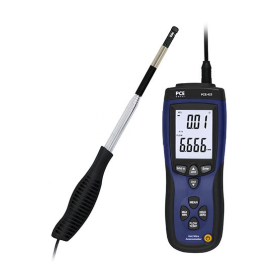
The Specification of Hot Wire Anemometer
Manual PCE-423
Advertisement
Table of Contents

Related Manuals for PCE Instruments PCE-423


Summary of Contents for PCE Instruments PCE-423
- Page 1 Tursdale Technical Services Ltd Unit N12B Tursdale Business Park Co. Durham DH6 5PG United Kingdom Phone: +44 ( 0 ) 191 377 3398 Fax: +44 ( 0 ) 191 377 3357 info@tursdaletechnicalservices.co.uk http://www.industrial-needs.com/ The Specification of Hot Wire Anemometer Manual PCE-423...
-
Page 2: Table Of Contents
info@tursdaletechnicalservices.co.uk Table of contents 1. Instructions ....................3 Features ......................3 2. Specifications ....................4 3. Button ......................5 4. Display Elements ..................6 4.1 Changing Setup Options................7 4.2 Setup Options ..................7 4.3 Entering or Exiting Setup ................. 7 4.4 Changing a Setup Option ................ -
Page 3: Instructions
info@tursdaletechnicalservices.co.uk 1. Instructions Your purchase of this HOT WIRE ANEMOMETER makes a step forward for you into the field of precision measurement. Although this ANEMOMETER is a complex and delicate instrument, its durable structure will allow many years of use if proper operating techniques are developed. Please read the following instructions carefully and always keep this manual within easy reach.. -
Page 4: Specifications
info@tursdaletechnicalservices.co.uk 2. Specifications General Specifications Display 46.7mm × 60 mm larger LCD display. Dual function meter’s display. m/s ( meters per second ) km/h (kilometers per hour ) ft/min (feet per minute) (miles per hour) measurement knots ( nautical miles per hour ) Temp. -
Page 5: Button
info@tursdaletechnicalservices.co.uk 3. Button 1, Press .The thermal sensor is heated up (5s). Measurement view is opened: The current reading is displayed, or “――――”lights up if no reading is available. Press again, turn off the instrument. 2, Press to freeze or unfreeze the displayed readings or air velocity Zero Adjust. 3, Press to enter a Setup option. -
Page 6: Display Elements
info@tursdaletechnicalservices.co.uk 4. Display Elements 1. Low Power. 2. Primary Display: air velocity, recording data or time. 3. Air velocity units. 4. Secondly display data. 5. Secondly display: air flow, temperature, or air velocity data. 6. Record MAX, MIN display. 7. Sign of multi-point mean calculation. 8. -
Page 7: Changing Setup Options
info@tursdaletechnicalservices.co.uk 4.1 Changing Setup Options Use Setup to change area unit, flow area, sleep mode settings. The thermometer stores the settings in its memory. 4.2 Setup Options Option Menu Settings item Chose area Unit set area unit unit Change the area set area of measuring air flow area... -
Page 8: Area Unit Setting
info@tursdaletechnicalservices.co.uk 4.5 Area unit Setting When the thermometer is in Setup mode, press scroll to the area unit setup option (refer Fig.2). Fig 1 Press button., The string “AREA” and area unit shows in the screen. Press to scroll to unit that you want to change((refer Fig.3). -
Page 9: Auto Power Off Mode
info@tursdaletechnicalservices.co.uk 4.7 Auto Power Off Mode The thermometer enters sleep mode (default). That is to say, the meter will automatically shut off after 20 minutes if no button press occurs for 20 minutes. When the thermometer is in Setup mode, the display shows SETUP. Press to scroll to the “... - Page 10 info@tursdaletechnicalservices.co.uk 5. Slide the sensor cover to the down position, let the air velocity sensor to contact the air, refer Fig.2. Extent the telescope probe to the convenient length, refer Fig.4. Air velocity sensor Fig 2 Fig.3 6. Direction of the sensor head: There is mark on the top of the “Sensor Head”, When make the measurement, then this mark should against the measured wind, refer Fig.
-
Page 11: Performing A Multi-Point Mean Calculation
info@tursdaletechnicalservices.co.uk Air velocity sensor Sensor head (top view) Flow Direction mark should face the measured wind. Probe Handle Fig.4 Fig.5 6. Performing a multi-point mean calculation 1. Press is lit. The number of readings recorded is displayed in the upper line, while the current reading is displayed in the lower line. -
Page 12: Performing A Mean Calculation In Time
info@tursdaletechnicalservices.co.uk 7. Performing a mean calculation in time 1. Press for 2 seconds. is lit. The elapsed measuring time (mm:ss) is displayed in the upper line, while the current reading is displayed in the lower line. 2. To change between displaying the temperature, flow velocity and calculated Flow volumetric flow rate: Press Temp... -
Page 13: Replacing The Batteries
info@tursdaletechnicalservices.co.uk 10. Replacing the Batteries 1. Turn off the thermometer if necessary. 2. Loosen the screw and remove the battery door. 3. Replace 9V batteries. 4. Replace the battery door and tighten the screw. In this direction will find a vision of the measurement technique: http://www.industrial-needs.com/measuring-instruments.htm NOTE: "This instrument doesn’t have ATEX protection, so it should not be used in potentially explosive atmospheres (powder, flammable gases)."...
Need help?
Do you have a question about the PCE-423 and is the answer not in the manual?
Questions and answers