Table of Contents
Advertisement
Quick Links
Advertisement
Table of Contents

Related Manuals for Rohde & Schwarz R&S FSWP


Summary of Contents for Rohde & Schwarz R&S FSWP
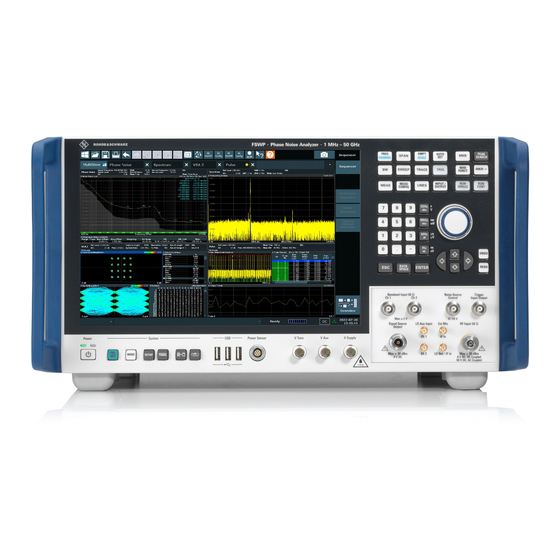
- Page 1 ® R&S FSWP Phase Noise Analyzer Getting Started (;ÛÇÆ2) 1177575602 Version 14...
- Page 2 ® This manual describes the following R&S FSWP models with firmware version 3.00 or higher: ● R&S ® FSWP8 (1322.8003K08) ● R&S ® FSWP8 (1322.8003K09) ● R&S ® FSWP26 (1322.8003K26) ● R&S ® FSWP26 (1322.8003K27) ● R&S ® FSWP50 (1322.8003K50) ●...
-
Page 3: Table Of Contents
® Contents R&S FSWP Contents 1 Safety and regulatory information........9 1.1 Safety instructions................9 1.2 Warning messages in the documentation........12 1.3 Korea certification class A..............13 2 Documentation overview............ 14 2.1 Getting started manual...............14 2.2 User manuals and help...............14 2.3 Service manual..................14 2.4 Instrument security procedures............ - Page 4 ® Contents R&S FSWP 3.10 Windows operating system..............25 3.11 Logging on..................27 3.12 Checking the supplied options............29 3.13 Performing a self-alignment.............. 30 3.14 Considerations for test setup............30 4 Instrument tour..............32 4.1 The front panel..................32 4.1.1 Display (touchscreen)................33 4.1.2 Power key.....................
- Page 5 ® Contents R&S FSWP 4.2.3 Display port and DVI................46 4.2.4 LAN....................... 47 4.2.5 USB ports....................47 4.2.6 IF / video / demod output..............47 4.2.7 IF Wide Out...................48 4.2.8 Sync trigger input and output..............48 4.2.9 AUX Port....................48 4.2.10 GPIB Interface..................49 4.2.11 External Generator Control (Optional)..........
- Page 6 ® Contents R&S FSWP 5.3.4 Miscellaneous evaluation tools............. 68 5.4 Measurement configuration...............69 5.4.1 Frequency configuration............... 70 5.4.2 The half decade configuration table............71 5.4.3 Pulsed measurement configuration............72 5.4.4 Signal generation.................. 73 5.4.5 DUT power supply................75 6 Operating the instrument............76 6.1 Understanding the display information..........
- Page 7 ® Contents R&S FSWP 6.6 Displaying results................97 6.6.1 Activating and deactivating channels............98 6.6.2 Laying out the result display with the smartgrid........99 6.6.3 Changing the size of windows............104 6.6.4 Switching between a split and maximized window display....105 6.6.5 Changing the display................
- Page 8 ® Contents R&S FSWP Getting Started 1177.5756.02 ─ 14...
-
Page 9: Safety And Regulatory Information
® Safety and regulatory information R&S FSWP Safety instructions Safety and regulatory information The product documentation helps you use the product safely and efficiently. Fol- low the instructions provided here and in the following chapters. Intended use The product is intended for the development, production and verification of elec- tronic components and devices in industrial, administrative, and laboratory envi- ronments. - Page 10 ® Safety and regulatory information R&S FSWP Safety instructions Using the product requires specialists or specially trained personnel. These users also need sound knowledge of at least one of the languages in which the user interfaces and the product documentation are available. Reconfigure or adjust the product only as described in the product documentation or the data sheet.
- Page 11 ® Safety and regulatory information R&S FSWP Safety instructions If the product has foldable feet, always fold the feet completely in or out to ensure stability. The feet can collapse if they are not folded out completely or if the prod- uct is moved without lifting it.
-
Page 12: Warning Messages In The Documentation
® Safety and regulatory information R&S FSWP Warning messages in the documentation these requirements, provide an easily accessible circuit breaker at the system level. Cleaning the product Use a dry, lint-free cloth to clean the product. When cleaning, keep in mind that the casing is not waterproof. -
Page 13: Korea Certification Class A
® Safety and regulatory information R&S FSWP Korea certification class A CAUTION Potentially hazardous situation. Could result in minor or moderate injury if not avoided. NOTICE Potential risks of damage. Could result in damage to the supported product or to other property. -
Page 14: Documentation Overview
® Documentation overview R&S FSWP Service manual Documentation overview This section provides an overview of the R&S FSWP user documentation. Unless specified otherwise, you find the documents at: www.rohde-schwarz.com/manual/FSWP Getting started manual Introduces the R&S FSWP and describes how to set up and start working with the product. -
Page 15: Instrument Security Procedures
® Documentation overview R&S FSWP Release notes and open source acknowledgment (OSA) The service manual is available for registered users on the global Rohde & Schwarz information system (GLORIS): https://gloris.rohde-schwarz.com Instrument security procedures Deals with security issues when working with the R&S FSWP in secure areas. It is available for download on the Internet. -
Page 16: Application Notes, Application Cards, White Papers, Etc
® Documentation overview R&S FSWP Application notes, application cards, white papers, etc. www.rohde-schwarz.com/firmware/FSWP Application notes, application cards, white papers, etc. These documents deal with special applications or background information on particular topics. www.rohde-schwarz.com/application/FSWP Getting Started 1177.5756.02 ─ 14... -
Page 17: Preparing For Use
® Preparing for use R&S FSWP Choosing the operating site Preparing for use Here, you can find basic information about setting up the product for the first time. Lifting and carrying The carrying handles are designed to lift or carry the instrument. Do not apply excessive external force to the handles. -
Page 18: Setting Up The R&S Fswp
® Preparing for use R&S FSWP Setting up the R&S FSWP Electromagnetic compatibility classes The electromagnetic compatibility (EMC) class indicates where you can operate the product. The EMC class of the product is given in the data sheet. ● Class B equipment is suitable for use in: –... -
Page 19: Mounting The R&S Fswp In A Rack
® Preparing for use R&S FSWP Setting up the R&S FSWP Left = Stacked correctly Right = Stacked incorrectly, too many products 3. NOTICE! Overheating can damage the product. Prevent overheating as follows: ● Keep a minimum distance of 10 cm between the fan openings of the prod- uct and any object in the vicinity. -
Page 20: Connecting The Ac Power
® Preparing for use R&S FSWP Connecting the AC power 3. Grab the handles and push the R&S FSWP onto the shelf until the rack brack- ets fit closely to the rack. 4. Tighten all screws in the rack brackets with a tightening torque of 1.2 Nm to secure the R&S FSWP in the rack. -
Page 21: Switching The Instrument On And Off
® Preparing for use R&S FSWP Switching the instrument on and off Switching the instrument on and off Table 3-1: Overview of power states Status LED on Power key Position of main power switch gray Standby orange Ready green To switch on the R&S FSWP The R&S FSWP is off but connected to power. -
Page 22: Connecting To Lan
® Preparing for use R&S FSWP Connecting to LAN If the instrument temperature exceeds the limit specified in the data sheet, the R&S FSWP automatically shuts down to protect the instrument from damage. To disconnect from power The R&S FSWP is in the standby state. 1. -
Page 23: Connecting A Keyboard
® Preparing for use R&S FSWP Connecting a keyboard ● Ensure that the network settings comply with the security policies of your com- pany. Contact your local system administrator or IT department before con- necting your product to your company LAN. ●... -
Page 24: Connecting An External Monitor
® Preparing for use R&S FSWP Connecting an external monitor ● Swiss ● French ● Russian To configure the keyboard language 1. To access the Windows operating system, press the Windows key on the external keyboard. 2. Select "Start > Settings > Time & language > Region & language > Add a lan- guage"... -
Page 25: Windows Operating System
® Preparing for use R&S FSWP Windows operating system 2. Press the [Setup] key. 3. Press the "Display" softkey. 4. Select the "Configure Monitor" tab in the "Display" dialog box. The standard Windows "Screen Resolution" dialog box is displayed. 5. Select the instrument for display: ●... - Page 26 ® Preparing for use R&S FSWP Windows operating system After the R&S FSWP is started, the operating system boots and the instrument firmware is started automatically. Tested software The drivers and programs used on the instrument under Microsoft Windows are adapted to the instrument.
-
Page 27: Logging On
® Preparing for use R&S FSWP Logging on For details and recommendations, see the following Rohde & Schwarz white paper: ● 1EF96: Malware Protection Windows 10 To access the "Start" menu The Windows "Start" menu provides access to the Microsoft Windows functional- ity and installed programs. - Page 28 ® Preparing for use R&S FSWP Logging on Some administrative tasks require administrator rights (e.g. the configuration of a LAN network). Refer to the description of the basic instrument Setup ([Setup] menu) to find out which functions are affected. Passwords For all default user accounts, the initial password is 894129.
-
Page 29: Checking The Supplied Options
® Preparing for use R&S FSWP Checking the supplied options 6. Enter the command C:\R_S\INSTR\USER\user\AUTOLOGIN.REG. 7. Press the [ENTER] key to confirm. The auto-login function is reactivated with the changed password. It will be applied the next time the instrument is switched on. Switching users when using the auto-login function Which user account is used is defined during login. -
Page 30: Performing A Self-Alignment
® Preparing for use R&S FSWP Considerations for test setup 3.13 Performing a self-alignment When temperature changes occur in the environment of the R&S FSWP, or after updating the firmware, you have to perform a self-alignment to align the data to a reference source. - Page 31 ® Preparing for use R&S FSWP Considerations for test setup To suppress electromagnetic radiation during operation: ● Use high-quality shielded cables, for example, double-shielded RF and LAN cables. ● Always terminate open cable ends. ● Ensure that connected external devices comply with EMC regulations. Signal input and output levels Information on signal levels is provided in the data sheet and on the instrument, next to the connector.
-
Page 32: Instrument Tour
® Instrument tour R&S FSWP The front panel Instrument tour On the instrument tour, you can learn about the different control elements and connectors on the front and back panel of the R&S FSWP. ● The front panel....................32 ● The rear panel....................44 The front panel... -
Page 33: Display (Touchscreen)
® Instrument tour R&S FSWP The front panel 9 = Signal source output (optional) 10 = Baseband connectors 11 = DC power connectors 12 = Power sensor connector 13 = USB 2.0 interfaces 14 = System control keys 15 = Power key 16 = Display (touchscreen) ●... - Page 34 ® Instrument tour R&S FSWP The front panel 1 = Toolbar: contains general functionality of the firmware. 2 = Channel tab: contains measurement channel. 3 = Channel bar: shows measurement settings. 4 = Result display: contains measurement results. 5 = Window title bar: contains diagram-specific (trace) information. 6 = Status bar: contains system messages, progress bar and date and time.
-
Page 35: Power Key
® Instrument tour R&S FSWP The front panel ● Scrolling through a result list ● Saving or printing results and settings To imitate a right-click by mouse using the touchscreen, for example to open a context-sensitive menu for a specific item, press the screen for about 1 second. 4.1.2 Power key The power key is on the lower left corner of the front panel. -
Page 36: The Function Keys
® Instrument tour R&S FSWP The front panel 4.1.4 The function keys Function keys provide access to the most common measurement settings and functions. Refer to the user manual for an extensive description of the measurement set- tings and functions. Provides functionality to define frequency parameters, for example: ●... -
Page 37: The Keypad
® Instrument tour R&S FSWP The front panel Provides functionality to position and control markers, for example: ● to configure the marker search ● to configure the peak excursion Provides the measurement functions, for example: ● the phase noise measurement ●... -
Page 38: Navigation Control
® Instrument tour R&S FSWP The front panel Select a particular unit for a numeric value. The labels on and next to the key state the units it selects. Pressing one of the unit keys also completes the entry of a numeric value. Note that in case of level entries (dB, dBm etc.) or dimensionless values, all unit keys have the value "1"... - Page 39 ® Instrument tour R&S FSWP The front panel knob. If the dialog box covers more than one screen page, it also scrolls through the dialog box. Turning it to the right corresponds to a downward movement. Moving it to the left to an upward movement.
-
Page 40: Rf Input (50 Ω)
® Instrument tour R&S FSWP The front panel The [UNDO] function is not available after a [PRESET] or "RECALL" opera- tion. When these functions are used, the history of previous actions is deleted. RF Input (50 Ω) 4.1.7 The RF Input allows you to connect a device under test (or DUT) to the R&S FSWP, usually via cable and an appropriate connector (for example a male N connector). -
Page 41: Usb Ports
® Instrument tour R&S FSWP The front panel Risk of damage to the R&S FSWP The maximum supported reverse power is 30 dBm. Make sure that this value is not exceeded to avoid damage to the R&S FSWP. The maximum DC output voltage is 0 V. For details on configuring the signal source output and generating a signal, see the User Manual. -
Page 42: Noise Source Control
® Instrument tour R&S FSWP The front panel The three-pinned probe power connector supports supply voltages from +15 V to -12.6 V and ground. The maximum permissible current is 150 mA. This probe power connector is suitable, for example, for high-impedance probes. 4.1.12 Noise source control The female BNC connector labeled "Noise Source"... -
Page 43: External Mixer (Optional)
® Instrument tour R&S FSWP The front panel Risk of instrument damage Do not overload the baseband input. An overload condition can damage or destroy the baseband inputs. For maximum allowed values, see the data sheet. 4.1.15 External Mixer (Optional) The two (optional) SMA connectors (LO OUT/IF IN and IF IN) allow you to con- nect external mixers. -
Page 44: Lo Aux Input (Optional)
® Instrument tour R&S FSWP The rear panel 4.1.17 LO AUX input (optional) The two optional connectors labeled "LO AUX Input - Ch1" and "LO AUX Input - Ch2" are two female SMA connectors that you can use to connect an external local oscillator (LO). - Page 45 ® Instrument tour R&S FSWP The rear panel Figure 4-2: Rear panel of the R&S FSWP 1 = DisplayPort and DVI 2 = Removable hard disk 3 = LAN interface 4 = USB ports 5 = Sync trigger input and output 6 = AUX port 7 = GPIB interface 8 = AC power connector and power switch...
-
Page 46: Removable Hard Disk
® Instrument tour R&S FSWP The rear panel ● ports......................47 ● IF / video / demod output................47 ● IF Wide Out..................... 48 ● Sync trigger input and output................48 ● Port......................48 ● GPIB Interface....................49 ● External Generator Control (Optional)............ -
Page 47: Lan
® Instrument tour R&S FSWP The rear panel ● Display Port ● DVI (digital visual interface) For details, see Chapter 3.9, "Connecting an external monitor", on page 24. 4.2.4 The R&S FSWP is equipped with a 1 GBit Ethernet IEEE 802.3u network inter- face with Auto-MDI(X) functionality. -
Page 48: If Wide Out
® Instrument tour R&S FSWP The rear panel 4.2.7 IF Wide Out You can extend the signal analysis bandwidth of the R&S FSWP by installing a hardware option. The bandwidth extension allows for a linear bandwidth up to 320 MHz. You can activate and deactivate the bandwidth extension manually in the I/Q ana- lyzer that is integral part of the optional spectrum analyzer (R&S FSWP-B1) or other optional applications that require the spectrum analyzer hardware. -
Page 49: Gpib Interface
® Instrument tour R&S FSWP The rear panel Short-circuit hazard Always observe the designated pin assignment. A short-circuit can damage the port. 4.2.10 GPIB Interface The GPIB interface is in compliance with IEEE488 and SCPI. A computer for remote control can be connected via this interface. To set up the connection, a shielded cable is recommended. -
Page 50: Ref Input / Ref Output
® Instrument tour R&S FSWP The rear panel 4.2.13 REF INPUT / REF OUTPUT The REF INPUT connectors are used to provide an external reference signal to the R&S FSWP. The REF OUTPUT connectors can be used to provide an external reference sig- nal (or the optional OCXO reference signal) from the R&S FSWP to other devices that are connected to this instrument. -
Page 51: Labels On R&S Fswp
® Instrument tour R&S FSWP The rear panel 4.2.14 Labels on R&S FSWP Labels on the casing inform about: ● Personal safety, see "Meaning of safety labels" on page 12 ● Product and environment safety, see Table 4-1 ● Identification of the product, see Chapter 4.2.15, "Device ID", on page 51... -
Page 52: Trying Out The Instrument
® Trying out the instrument R&S FSWP Trying out the instrument Overview of tutorials Initial setup: ● "Preparing the R&S FSWP" on page 54 ● "Selecting the phase noise application" on page 54 ● "Performing a preset" on page 54 Measurement selection ●... - Page 53 ® Trying out the instrument R&S FSWP Integration ranges ● "How to define integration ranges" on page 66 The cross-correlation gain indicator ● "How to control the cross-correlation gain indicator (gray area)" on page 68 Miscellaneous evaluation tools ● "Zooming into the results" on page 68 ●...
-
Page 54: Initial Setup
® Trying out the instrument R&S FSWP Initial setup Initial setup Preparing the R&S FSWP 1. Connect the R&S FSWP to an electrical outlet as described in Chapter 3.5, "Connecting the AC power", on page 20. 2. Turn on the R&S FSWP as described in Chapter 3.6, "Switching the instru- ment on and off",... -
Page 55: Measurements
® Trying out the instrument R&S FSWP Measurements 2. Enter the "Overview" dialog box and select the "Preset Channel" item to restore the default state of the selected measurement channel. All other mea- surement channels keep their custom configuration. Measurements Measuring the phase noise characteristics of a DUT requires a simple measure- ment setup consisting of the R&S FSWP and a DUT. -
Page 56: The Phase Noise Measurement
® Trying out the instrument R&S FSWP Measurements 5.2.2 The phase noise measurement Test setup Connect the DUT via cable to the RF input of the R&S FSWP as shown in the illustration. required connections R&S FSWP optional connections supply tune Figure 5-1: Typical test setup for basic noise measurements Measuring phase noise... - Page 57 ® Trying out the instrument R&S FSWP Measurements First, it searches for a carrier signal (see How to search for signals). When one has been found, it measures the noise characteristics of the DUT in the default measurement (or frequency offset) range. If no carrier could be found, a corresponding error message is displayed in the status bar below the diagram.
- Page 58 ® Trying out the instrument R&S FSWP Measurements In addition to the graphical representation of the phase noise characteristics, the application also provides several tables that show specific phase noise character- istics. Measuring spurs In addition to the graphical display of spurs in the diagram (spikes on the trace), the application also features a result display that contains a list of all detected spurs.
-
Page 59: The Additive Noise Measurement
® Trying out the instrument R&S FSWP Measurements The table contains a list of integrated measurement results. For more information on the table contents see the R&S FSWP user manual. Tip: You can define custom integration ranges in the "Integration Ranges" tab of the "Noise Config"... -
Page 60: The Baseband Noise Measurement
® Trying out the instrument R&S FSWP Measurements By default, two traces are displayed: the first trace shows the smoothed data without spurs, the second trace the raw data including spurs. 5.2.4 The baseband noise measurement Baseband Noise measurements measure the noise characteristics of a DUT over an absolute frequency span (not relative to carrier). -
Page 61: The Pulsed Phase Noise Measurement
® Trying out the instrument R&S FSWP Measurements Tip: Integrated measurement results. Note that the "PM", "FM" and "Jitter" results are always "0" for baseband noise measurements. 5.2.5 The pulsed phase noise measurement Noise measurements on pulses are available with the optional pulsed phase noise measurements firmware application. -
Page 62: The Pulsed Additive Noise Measurement
® Trying out the instrument R&S FSWP Measurements 5.2.6 The pulsed additive noise measurement Additive noise measurements on pulses require the optional pulsed phase noise measurements firmware application and the optional signal source output. The test setup depends on whether you use internal or external modulation with a pulse modulator. -
Page 63: Adding Another Measurement Channel
® Trying out the instrument R&S FSWP Result evaluation 5.2.7 Adding another measurement channel Measuring the noise characteristics in two different measurement channels allows you, for example, to capture and analyze two different data streams with different measurement configurations. Adding another measurement channel 1. - Page 64 ® Trying out the instrument R&S FSWP Result evaluation 2. Define the number of measurements to be performed in the "Sweep / Average Count" input field, for example "10". 3. Start the measurement. ● In case of a single measurement, the application performs x measure- ments over the frequency range you have defined.
- Page 65 ® Trying out the instrument R&S FSWP Result evaluation For more information on how cross-correlation works refer to the R&S FSWP user manual. How to smooth the trace graphically When you apply trace smoothing, the existing data remains the same. The trace is smoothed by applying mathematical operations Trace smoothing is applied to each trace individually.
-
Page 66: Integration Ranges
® Trying out the instrument R&S FSWP Result evaluation The application removes all signals that are above the threshold from the trace spur removal is applied to. Signals with levels below the threshold are not regarded as spurs and are still displayed. For more information about spur removal, refer to the R&S FSWP user man- ual. - Page 67 ® Trying out the instrument R&S FSWP Result evaluation 5. Define the frequency ranges ("Range Start" and "Range Stop") over which you would like to integrate. The application calculates the measurement results as defined. Results in the integrated measurements result table are adjusted accordingly (see "Measur- ing integrated noise"...
-
Page 68: The Cross-Correlation Gain Indicator
® Trying out the instrument R&S FSWP Result evaluation 5.3.3 The Cross-Correlation gain indicator How to control the cross-correlation gain indicator (gray area) The gray trace, or cross-correlation gain indicator, indicates the ideal position of the measurement trace for the current number of cross-correlation operations. Thus, the position of this area depends on the number of cross-correlations that are currently applied in each half decade. -
Page 69: Measurement Configuration
® Trying out the instrument R&S FSWP Measurement configuration 3. You can return to the full display anytime with the "Unzoom" icon in the toolbar ( ). Exporting measurement data Exporting measurement data to a .dat file allows you to archive that data in exter- nal programs like a spreadsheet. -
Page 70: Frequency Configuration
® Trying out the instrument R&S FSWP Measurement configuration 5.4.1 Frequency configuration How to define the measurement range The measurement range defines the carrier frequency offset over which the phase noise measurement takes place. 1. Enter the "Overview" dialog box, and from there, enter the "Noise Config" dia- log box. -
Page 71: The Half Decade Configuration Table
® Trying out the instrument R&S FSWP Measurement configuration When the application finds a signal with appropriate characteristics, it starts a phase noise measurement in the measurement range you have defined. Note: Automatic signal search is only available in phase noise and pulsed phase noise measurements. -
Page 72: Pulsed Measurement Configuration
® Trying out the instrument R&S FSWP Measurement configuration 4. In case of a manual configuration, define the resolution bandwidth and num- ber of cross-correlations for each half decade directly in the half decade con- figuration table as absolute values. The relative "RBW"... -
Page 73: Signal Generation
® Trying out the instrument R&S FSWP Measurement configuration For more information on the gate configuration, refer to the R&S FSWP user manual. Tip: You can turn off the gate, if one is not required for the measurement. To do so, select "Gate Type: Off". 5.4.4 Signal generation How to generate a CW signal... - Page 74 ® Trying out the instrument R&S FSWP Measurement configuration 5. Turn on the signal source with the "Source Power" feature. Tip: You can turn the signal source on and off effectively with the "RF On/Off" button in the toolbar. The "RF Config" button provides access to a softkey menu that lets you change the signal source characteristics without entering a dialog box.
-
Page 75: Dut Power Supply
® Trying out the instrument R&S FSWP Measurement configuration that lets you change the signal source characteristics without entering a dialog box. 5.4.5 DUT power supply How to supply DUTs with current or voltage Some measurement setups or DUTs require you to supply them with either volt- age or current. -
Page 76: Operating The Instrument
® Operating the instrument R&S FSWP Understanding the display information Operating the instrument The following topics provide an overview on how to work with the R&S FSWP. They describe what kind of information is displayed in the diagram area, how to operate the R&S FSWP via the front panel keys and other interaction methods, and how to use the Online Help. - Page 77 ® Operating the instrument R&S FSWP Understanding the display information 1 = Toolbar: contains general functionality of the firmware. 2 = Channel tab: contains measurement channel. 3 = Channel bar: shows measurement settings. 4 = Result display: contains measurement results. 5 = Window title bar: contains diagram-specific (trace) information.
-
Page 78: Channel Bar
® Operating the instrument R&S FSWP Understanding the display information ● Frequency information in diagram footer............83 ● Instrument and status information..............84 ● Error information..................... 85 6.1.1 Channel bar Using the R&S FSWP you can handle several different measurement tasks (channels) at the same time (although they can only be performed asynchro- nously). - Page 79 ® Operating the instrument R&S FSWP Understanding the display information trace is frozen and the instrument settings are changed. As soon as a new mea- surement is performed, the icon disappears. The exclamation mark ("!" or ) icon indicates that an error or warning is available for that measurement channel.
-
Page 80: Window Title Bar
® Operating the instrument R&S FSWP Understanding the display information Label Information Current number of measurements performed in a single sweep. Only displayed if you are in single sweep measurement mode. Count The current signal count for measurement tasks that involve a specific number of subsequent sweeps. -
Page 81: Marker Information
® Operating the instrument R&S FSWP Understanding the display information Trace Mode Abbreviation of the trace mode: ● Clrw Clear Write trace ● Max Hold trace ● Min Hold trace ● Average trace ● View Frozen trace ● Write Hold trace Result type Type of result the trace represents. -
Page 82: Spot Noise Information
® Operating the instrument R&S FSWP Understanding the display information Table 6-2: Regular marker table Label Information Window type the marker is positioned in. (Only if there is more than one window containing a phase noise dia- gram.) Type Marker type: N (normal), D (delta), T (temporary, internal) Reference (for delta markers) Trace to which the marker is assigned X-value... -
Page 83: Measurement Progress Information
® Operating the instrument R&S FSWP Understanding the display information 6.1.5 Measurement progress information The Phase Noise result display shows the progress of the measurement in a ser- ies of green bars at the bottom of the diagram area. For each half decade in the measurement, the R&S FSWP adds a bar that spans the frequency range of the corresponding half decade. -
Page 84: Instrument And Status Information
® Operating the instrument R&S FSWP Understanding the display information The contents depend on the application and the result display. Label Information Start offset Start offset frequency Stop offset Stop offset frequency 6.1.7 Instrument and status information Global instrument settings and functions, the instrument status and any irregulari- ties are indicated in the status bar beneath the diagram. -
Page 85: Error Information
® Operating the instrument R&S FSWP Understanding the display information In the MultiView tab, the progress bar indicates the status of the currently selected measurement, not the measurement currently being performed by a Sequencer, for example. Date and time The date and time settings of the instrument are displayed in the status bar. Error messages and warnings If errors or irregularities are detected, a keyword and an error message, if availa- ble, are displayed in the status bar. -
Page 86: Accessing Functions
® Operating the instrument R&S FSWP Accessing functions If any error information is available for a measurement channel, an exclama- tion mark is displayed next to the channel name ( ). This is particularly use- ful when the MultiView tab is displayed, as the status bar in the MultiView tab always displays the information for the currently selected measurement only. -
Page 87: Toolbar
® Operating the instrument R&S FSWP Accessing functions ● Using other elements provided by the front panel, for example the keypad, rotary knob, or arrow and position keys. The measurement and instrument functions and settings can be accessed by selecting one of the following elements: ●... - Page 88 ® Operating the instrument R&S FSWP Accessing functions Redo: repeats previously reverted operation Select: the cursor can be used to select (and move) elements in the display (markers, lines etc.). Zoom mode: displays a dotted rectangle in the diagram that can be expan- ded to define the zoom area.
-
Page 89: Softkeys
® Operating the instrument R&S FSWP Accessing functions 6.2.2 Softkeys Softkeys are virtual keys provided by the software. Thus, more functions can be provided than those that can be accessed directly via the function keys on the instrument. Softkeys are dynamic: depending on the selected function key, a dif- ferent list of softkeys is displayed on the right side of the screen. -
Page 90: On-Screen Keyboard
® Operating the instrument R&S FSWP Accessing functions 6.2.4 On-screen keyboard The on-screen keyboard is an additional means of interacting with the instrument without having to connect an external keyboard. The on-screen keyboard display can be switched on and off as desired using the "On-Screen Keyboard"... -
Page 91: Changing The Focus
® Operating the instrument R&S FSWP Entering data You can use the TAB key on the on-screen keyboard to move the focus from one field to another in dialog boxes. Changing the focus Any selected function is always performed on the currently focused element in the display, e.g. -
Page 92: Entering Numeric Parameters
® Operating the instrument R&S FSWP Entering data Transparent dialog boxes You can change the transparency of the dialog boxes to see the results in the windows behind the dialog box. Thus, you can see the effects that the changes you make to the settings have on the results immediately. To change the transparency, select the transparency icon at the top of the dialog box. - Page 93 ® Operating the instrument R&S FSWP Entering data Alternatively, you can use the keypad. Every alphanumeric key represents sev- eral characters and one number. The decimal point key (.) represents special characters, and the sign key (-) toggles between capital and small letters. For the assignment, refer to Table 6-6.
-
Page 94: Touchscreen Gestures
® Operating the instrument R&S FSWP Touchscreen gestures To complete the entry ► Press the [ENTER] key or the rotary knob. To abort the entry ► Press the [ESC] key. The dialog box is closed without changing the settings. Table 6-6: Keys for alphanumeric parameters Key name Series of (special) characters and number provided (upper inscription) - Page 95 ® Operating the instrument R&S FSWP Touchscreen gestures You can tap most elements on the screen; in particular, any elements you can also click on with a mouse pointer. Figure 6-1: Tapping Double-tapping Tap the screen twice, in quick succession. Double-tap a diagram or the window title bar to maximize a window in the display, or to restore the original size.
- Page 96 ® Operating the instrument R&S FSWP Touchscreen gestures You can pinch or spread your fingers vertically, horizontally, or diagonally. The direction in which you move your fingers determines which dimension of the dis- play is changed. Figure 6-3: Pinching Figure 6-4: Spreading Touch gestures in diagrams change measurement settings When you change the display using touch gestures, the corresponding mea- surement settings are adapted.
-
Page 97: Displaying Results
® Operating the instrument R&S FSWP Displaying results Table 6-7: Correlation of mouse and touch actions Mouse operation Touch operation Click Double-click Double-tap Click and hold Touch and hold Right-click Touch, hold for 1 second and release Drag-&-drop (= click and hold, then drag and Touch, then drag and release release) Mouse wheel to scroll up or down... -
Page 98: Activating And Deactivating Channels
® Operating the instrument R&S FSWP Displaying results 6.6.1 Activating and deactivating channels When you activate an application, a new measurement channel is created which determines the measurement settings for that application. The same application can be activated with different measurement settings by creating several chan- nels for the same application. -
Page 99: Laying Out The Result Display With The Smartgrid
® Operating the instrument R&S FSWP Displaying results To change the application in an active channel 1. Select the tab of the channel you want to change. 2. Select the [Mode] key. 3. In the "Mode" dialog box, select the new application to be displayed on the "Replace Current Channel"... - Page 100 ® Operating the instrument R&S FSWP Displaying results The same evaluation method can be displayed in multiple windows simultane- ously. ● New windows are added by dragging an evaluation icon from the evaluation bar to the screen. The position of each new window depends on where you drop the evaluation icon in relation to the existing windows.
- Page 101 ® Operating the instrument R&S FSWP Displaying results Figure 6-5: Moving a window in SmartGrid mode The brown area indicates the possible "drop area" for the window, i.e. the area in which the window can be placed. A blue area indicates the (approximate) layout of the window as it would be if the icon were dropped at the current position.
- Page 102 ® Operating the instrument R&S FSWP Displaying results Figure 6-6: SmartGrid window positions 1 = Insert row above or below the existing row 2 = Create a new column in the existing row 3 = Replace a window in the existing row SmartGrid functions Once the evaluation icon has been dropped, icons in each window provide delete and move functions.
- Page 103 ® Operating the instrument R&S FSWP Displaying results To close the SmartGrid mode and restore the previous softkey menu select the "Close" icon in the right-hand corner of the toolbar, or press any key. 6.6.2.3 How to add a new result window Each type of evaluation is displayed in a separate window.
-
Page 104: Changing The Size Of Windows
® Operating the instrument R&S FSWP Displaying results 2. Drag the evaluation over the SmartGrid. A blue area shows where the window will be placed. 3. Move the window until a suitable area is indicated in blue. 4. Drop the window in the target area. The windows are rearranged to the selected layout, and "Delete"... -
Page 105: Switching Between A Split And Maximized Window Display
® Operating the instrument R&S FSWP Displaying results The splitters are not available in SmartGrid mode. ► To change the size of two neighboring windows, drag the splitter between the windows in either direction. 6.6.4 Switching between a split and maximized window display To get an overview of the results, displaying several windows at the same time may be helpful. -
Page 106: Remote Control
® Operating the instrument R&S FSWP Remote control Remote control In addition to working with the R&S FSWP interactively, located directly at the instrument, it is also possible to operate and control it from a remote PC. Various methods for remote control are supported: ●... -
Page 107: Contacting Customer Support
® Contacting customer support R&S FSWP Contacting customer support Technical support – where and when you need it For quick, expert help with any Rohde & Schwarz product, contact our customer support center. A team of highly qualified engineers provides support and works with you to find a solution to your query on any aspect of the operation, program- ming or applications of Rohde &... -
Page 108: Index
® Index R&S FSWP Index OCXO ..........49 Probe Power ........41 Alphanumeric keys ........37 RF INPUT ........... 40 Alphanumeric parameters ....... 92 Signal source output ......40 AM (trace information) ......81 SYNC TRIGGER ........ 48 Application cards ........16 Trigger Input ........42 Application notes ........ - Page 109 ® Index R&S FSWP Evaluation Modes, adding ........103 Evaluation bar POWER ..........35 Using ..........103 Redo ........... 39 EXT REF Undo ........... 39 Status message ........84 Keyboard External generators ......... 49 On-screen ........... 90 External Mixer ......... 43 Keypad ............
- Page 110 ® Index R&S FSWP Signal level (channel bar) ......79 Signal source output ........40 OCXO ............49 SmartGrid On-screen keyboard ......90, 92 Activating .......... 102 Online keyboard ........35 Arranging windows ......103 OVEN (status display) ......86 Display ..........99 Overheating Evaluation bar ........
- Page 111 ® Index R&S FSWP UNCAL Error ............ 86 Undo ..........38, 39 Connector ........... 47 USB port ..........41 VIEW (trace information) ......81 White papers ........... 16 Window title bar ........80 Windows Adding ..........103 Arranging .......... 103 Closing ..........103 Dialog boxes ........
Need help?
Do you have a question about the R&S FSWP and is the answer not in the manual?
Questions and answers