Table of Contents
Advertisement
Quick Links
Advertisement
Chapters
Table of Contents

Subscribe to Our Youtube Channel
Related Manuals for Rohde & Schwarz FSPN


Summary of Contents for Rohde & Schwarz FSPN
- Page 1 ® R&S FSPN Phase Noise Analyzer Getting Started (;Ý[Ô2) 1179437002 Version 01...
- Page 2 Rohde & Schwarz GmbH & Co. KG. Trade names are trademarks of the owners. ® 1179.4370.02 | Version 01 | R&S FSPN Throughout this manual, products from Rohde & Schwarz are indicated without the ® symbol, e.g. ® R&S FSPN is indicated as R&S FSPN.
- Page 3 ® Safety and Regulatory Information R&S FSPN Safety Instructions Safety and Regulatory Information The product documentation helps you use the product safely and efficiently. Fol- low the instructions provided here and in the Chapter 1.1, "Safety Instructions", on page 3.
- Page 4 ® Safety and Regulatory Information R&S FSPN Safety Instructions Using the product requires specialists or specially trained personnel. These users also need sound knowledge of at least one of the languages in which the user interfaces and the product documentation are available.
- Page 5 ® Safety and Regulatory Information R&S FSPN Safety Instructions uct is moved without lifting it. The foldable feet are designed to carry the weight of the product, but not an extra load. If stacking is possible, keep in mind that a stack of products can fall over and cause injury.
- Page 6 ® Safety and Regulatory Information R&S FSPN Warning Messages in the Documentation Cleaning the product Use a dry, lint-free cloth to clean the product. When cleaning, keep in mind that the casing is not waterproof. Do not use liquid cleaning agents.
- Page 7 ® Safety and Regulatory Information R&S FSPN Korea Certification Class A NOTICE Potential risks of damage. Could result in damage to the supported product or to other property. Korea Certification Class A 이 기기는 업무용(A급) 전자파 적합기기로서 판매자 또는 사용자는 이 점을 주의하...
- Page 8 R&S FSPN product page at: www.rohde-schwarz.com/manual/FSPN Getting Started Manual Introduces the R&S FSPN and describes how to set up and start working with the product. Includes basic operations, typical measurement examples, and general information, e.g. safety instructions, etc.
- Page 9 Rohde & Schwarz information system (GLORIS): https://gloris.rohde-schwarz.com Instrument Security Procedures Deals with security issues when working with the R&S FSPN in secure areas. It is available for download on the Internet. Printed Safety Instructions Provides safety information in many languages. The printed document is deliv- ered with the product.
- Page 10 ® Documentation Overview R&S FSPN Application Notes, Application Cards, White Papers, etc. www.rohde-schwarz.com/firmware/FSPN Application Notes, Application Cards, White Papers, etc. These documents deal with special applications or background information on particular topics. www.rohde-schwarz.com/application/FSPN Getting Started 1179.4370.02 ─ 01...
- Page 11 "Lifting and carrying the product" on page 4. Unpacking and Checking 1. Unpack the R&S FSPN carefully. 2. Retain the original packing material. Use it when transporting or shipping the R&S FSPN later. 3. Using the delivery notes, check the equipment for completeness.
- Page 12 If class A equipment causes radio disturbances, take appropriate measures to eliminate them. Setting Up the R&S FSPN The R&S FSPN is designed for use on a bench top or in a rack. See also: ● "Setting up the product"...
- Page 13 To mount the R&S FSPN in a rack 1. Use an adapter kit to prepare the R&S FSPN for rack mounting. a) Order the rack adapter kit designed for the R&S FSPN. For the order num- ber, see the data sheet.
- Page 14 FSPN Connecting the AC Power 3. Grab the handles and push the R&S FSPN onto the shelf until the rack brack- ets fit closely to the rack. 4. Tighten all screws in the rack brackets with a tightening torque of 1.2 Nm to secure the R&S FSPN in the rack.
- Page 15 ► Press the [Power] key. The operating system shuts down. The LED changes to orange. If the instrument temperature exceeds the limit specified in the data sheet, the R&S FSPN automatically shuts down to protect the instrument from damage. Getting Started 1179.4370.02 ─ 01...
- Page 16 Switch", on page 37. The LED of the standby key is switched off. 2. Disconnect the R&S FSPN from the power source. Connecting to LAN You can connect the instrument to a LAN for remote operation via a PC. Provided the network administrator has assigned you the appropriate rights and...
- Page 17 ● Changing IP addresses ● Exchanging hardware Errors can affect the entire network. Connect the R&S FSPN to the LAN via the LAN interface on the rear panel of the instrument. Windows automatically detects the network connection and activates the required drivers.
- Page 18 38). Screen resolution and format The touchscreen of the R&S FSPN is calibrated for a 16:10 format. If you connect a monitor or projector using a different format (e.g. 4:3), the calibra- tion is not correct and the screen does not react to your touch actions prop- erly.
- Page 19 After the R&S FSPN is started, the operating system boots and the instrument firmware is started automatically.
- Page 20 ® Preparing for Use R&S FSPN Windows Operating System Tested software The drivers and programs used on the instrument under Microsoft Windows are adapted to the instrument. Only install update software released by Rohde & Schwarz to modify existing instrument software.
- Page 21 3.11 Logging On Microsoft Windows requires that users identify themselves by entering a user name and password in a login window. By default, the R&S FSPN provides two user accounts: ● "Instrument": a standard user account with limited access ● "Admin" or "Administrator" (depends on firmware image): an administrator account with unrestricted access to the computer/domain Some administrative tasks require administrator rights (e.g.
- Page 22 ® Preparing for Use R&S FSPN Logging On Passwords For all default user accounts, the initial password is 894129. Note that this pass- word is very weak, and it is recommended that you change the password for both users after initial login. An administrator can change the password in Microsoft Windows for any user at any time via "Start >...
- Page 23 However, you can switch the user account to be used even when the auto-login function is active. 1. Select the "Windows" icon in the toolbar to access the operating system of the R&S FSPN (see also "To access the "Start" menu" on page 21).
- Page 24 Considerations for Test Setup 3.13 Performing a Self-Alignment When strong temperature changes occur in the environment of the R&S FSPN, or after updating the firmware, you have to perform a self-alignment to align the data to a reference source. During self-alignment, do not connect a signal to the RF input connector. Running a self-alignment with a signal connected to the RF input can lead to false mea- surement results.
- Page 25 Use a conductive floor mat and heel strap combination. Signal input and output levels Information on signal levels is provided in the data sheet. Keep the signal levels within the specified ranges to avoid damage to the R&S FSPN and connected devices. Getting Started 1179.4370.02 ─ 01...
- Page 26 Instrument Tour R&S FSPN Front Panel View Instrument Tour On the instrument tour, you can learn about the different control elements and connectors on the front and back panel of the R&S FSPN. ● Front Panel View..................... 26 ● Rear Panel View....................36...
-
Page 27: Table Of Contents
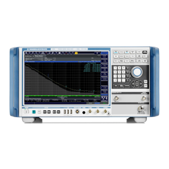
Supply....................35 4.1.1 Display (Touchscreen) The touchscreen on the front panel of the R&S FSPN displays the measurement results. Additionally, the screen display provides status and setting information and allows you to switch between various measurement tasks. The screen is touch-sensitive, offering an alternative means of user interaction for quick and easy handling of the instrument. - Page 28 ® Instrument Tour R&S FSPN Front Panel View 1 = Toolbar: contains general functionality of the firmware. 2 = Channel tab: contains measurement channel. 3 = Channel bar: shows measurement settings. 4 = Result display: contains measurement results. 5 = Window title bar: contains diagram-specific (trace) information.
-
Page 29: Power Key
® Instrument Tour R&S FSPN Front Panel View ● Scrolling through a result list ● Saving or printing results and settings To imitate a right-click by mouse using the touchscreen, for example to open a context-sensitive menu for a specific item, press the screen for about 1 second. -
Page 30: The Function Keys
® Instrument Tour R&S FSPN Front Panel View 4.1.4 The Function Keys Function keys provide access to the most common measurement settings and functions. Refer to the user manual for an extensive description of the measurement set- tings and functions. -
Page 31: The Keypad
® Instrument Tour R&S FSPN Front Panel View Provides functionality to configure the measurement. Provides functionality to control display and limit lines. Provides functionality to configure inputs and outputs. Starts a measurement in single measurement mode. Starts a measurement in continuous measurement mode. -
Page 32: Navigation Control
® Instrument Tour R&S FSPN Front Panel View Provides the following functions: In dialog boxes: ● Closes all kinds of dialog boxes if edit mode is not active. ● Quits edit mode if it is active. ● Selects the "Cancel" button when available. - Page 33 ® Instrument Tour R&S FSPN Front Panel View ● It moves around markers and other graphical elements on the screen. In most cases, the step size is fix. ● Pressing the rotary knob has the same effect as pressing the [ENTER] key as it confirms an entry or selection.
-
Page 34: Rf Input 50 Ohm
4.1.7 RF Input 50 Ohm Provides RF input from a connected device under test (DUT) to the R&S FSPN, which is then analyzed in an RF measurement. Connect the DUT to the "RF Input" connector on the R&S FSPN. Do not overload the input. For maximum allowed values, see the data sheet. -
Page 35: Baseband Input
® Instrument Tour R&S FSPN Front Panel View The three-pinned probe power connector supports supply voltages from +15 V to -12.6 V and ground. The maximum permissible current is 150 mA. This probe power connector is suitable, for example, for high-impedance probes. - Page 36 For more information about configuring the DC Power supply, refer to the User Manual. Rear Panel View This figure shows the rear panel view of the R&S FSPN. The individual elements are described in more detail in the subsequent sections. Figure 4-2: Rear panel of the R&S FSPN...
- Page 37 The removable hard disk is accessible from the rear of the instrument. In addition to the operating system and the firmware, the R&S FSPN also stores measurement data on that disk. When you remove the hard disk, you can store it and the data on it somewhere secure.
-
Page 38: Display (Touchscreen)
The four USB ports on the rear panel (type A) allow you to connect devices like keyboards, mouses or memory sticks. The male USB connector (type B) allows you to connect the R&S FSPN to a com- puter and establish a remote control connection, for example. -
Page 39: Aux. Port
The GPIB interface is in compliance with IEEE488 and SCPI. A computer for remote control can be connected via this interface. To set up the connection, a shielded cable is recommended. For more details, refer to "Setting Up Remote Control" in the R&S FSPN user manual. 4.2.9 OCXO The OCXO generates a 10 MHz reference signal with a very precise frequency. -
Page 40: Labels On R&Sfspn
ID", on page 40 Table 4-1: Labels regarding R&S FSPN and environment safety Labeling in line with EN 50419 for disposal of electrical and electronic equipment after the product has come to the end of its service life. For more information, see the prod- uct user manual, chapter "Disposal". - Page 41 ® Instrument Tour R&S FSPN Rear Panel View It consists of the device order number and a serial number. The serial number is used to define the default instrument name, which is: <Type><variant>-<serial_number> For example, FSPN6-123456. The instrument name is required to establish a connection to the instrument in a LAN.
- Page 42 ® Trying Out the Instrument R&S FSPN Trying Out the Instrument Overview of tutorials Initial setup: ● "Preparing the R&S FSPN" on page 43 ● "Selecting the phase noise application" on page 43 ● "Performing a preset" on page 44 Measurement selection ●...
- Page 43 Evaluation.................... 49 ● Measurement Configuration................54 Initial Setup Preparing the R&S FSPN 1. Connect the R&S FSPN to an electrical outlet as described in Chapter 3.5, "Connecting the AC Power", on page 14. 2. Turn on the R&S FSPN as described in Chapter 3.6, "Switching the Instru-...
- Page 44 Measurements There's more than one way to skin a cat In most cases, the firmware of the R&S FSPN provides several ways to change measurement parameters. For example, the measurement range can be defined via the [FREQ] key, the "MEAS CONFIG" key or the "Over- view"...
- Page 45 The R&S FSPN opens a dialog box to select the measurement. 5.2.2 Phase Noise Measurement Test setup Connect the DUT via cable to the RF input of the R&S FSPN as shown in the illustration. required connections R&S FSPN optional connections...
- Page 46 ® Trying Out the Instrument R&S FSPN Measurements By default, two traces are displayed: the first trace shows the smoothed data without spurs, the second trace the raw data including spurs. Measuring amplitude noise The test setup is the same as shown above.
- Page 47 The table contains a list of spot noise values for selected frequency offsets (in the default state, these are the decade edges) on each active trace. For more information on the table contents see the R&S FSPN user manual. Tip: You can define custom spot noise frequencies in the "Spot Noise" tab of the "Noise Config"...
- Page 48 Trying Out the Instrument R&S FSPN Measurements Test setup required connections R&S FSPN optional connections supply tune RF / BB* * = See text below for instructions on how to use the baseband input. How to measure baseband noise at the RF input For baseband noise measurements on the RF input, proceed as follows.
- Page 49 ® Trying Out the Instrument R&S FSPN Result Evaluation The firmware adds a second instance of the phase noise application which is independent of the first one. Result Evaluation The phase noise application provides several tools to control the data displayed in the various result displays.
- Page 50 You can also see the resulting number of operations in the green bar at the bottom of the diagram area. For more information on how cross-correlation works refer to the R&S FSPN user manual. How to smooth the trace graphically When you apply trace smoothing, the existing data remains the same.
- Page 51 FSPN Result Evaluation Trace smoothing is applied immediately after you have applied it to a trace. For more information on how this is done, refer to the R&S FSPN user man- ual. How to remove spurs from a trace By default, the application already shows a trace without spurs (the yellow one).
- Page 52 Note that the integration ranges are displayed graphically in the noise dia- gram. Figure 5-3: Custom integration ranges are represented in the diagram as colored lines For more information on integrated measurement result calculation refer to the R&S FSPN user manual. Getting Started 1179.4370.02 ─ 01...
- Page 53 ® Trying Out the Instrument R&S FSPN Result Evaluation 5.3.3 Cross-Correlation Gain Indicator How to control the cross-correlation gain indicator (gray area) The gray trace, or cross-correlation gain indicator, indicates the ideal position of the measurement trace for the current number of cross-correlation operations.
- Page 54 ® Trying Out the Instrument R&S FSPN Measurement Configuration 3. You can return to the full display any time with the "Unzoom" icon in the tool- bar ( ). Exporting measurement data Exporting measurement data to a .dat file allows you to archive that data in exter- nal programs like a spreadsheet.
- Page 55 Note: In case of baseband measurements, the measurement range is defined by an absolute start and stop frequency instead of offsets. For more information on the measurement range, refer to the R&S FSPN user manual. How to search for signals The application allows you to search for a carrier signal, instead of defining the carrier frequency manually.
- Page 56 Some measurement setups or DUTs require you to supply them with either volt- age or current. The R&S FSPN can provide both, when you set it up that way. 1. Enter the "Overview" dialog box and, from there, enter the "Output" dialog box.
- Page 57 ● Define limits for the outputs. When you define limits, the supplied voltage will not go below or above these. For more information on configuring DC outputs, refer to the R&S FSPN user manual. 3. Turn on the output of voltage or current with the "DC Power" feature.
-
Page 58: Understanding The Display Information
Understanding the Display Information Operating the Instrument The following topics provide an overview on how to work with the R&S FSPN. They describe what kind of information is displayed in the diagram area, how to operate the R&S FSPN via the front panel keys and other interaction methods, and how to use the Online Help. - Page 59 6.1.1 Channel Bar Using the R&S FSPN you can handle several different measurement tasks (chan- nels) at the same time (although they can only be performed asynchronously). For each channel, a separate tab is displayed on the screen. In order to switch from one channel display to another, simply select the corresponding tab.
- Page 60 ® Operating the Instrument R&S FSPN Understanding the Display Information MultiView tab An additional tab labelled "MultiView" provides an overview of all active channels at a glance. In the "MultiView" tab, each individual window contains its own chan- nel bar with an additional button. Tap this button to switch to the corresponding channel display quickly.
- Page 61 6.1.2 Window Title Bar Each channel in the R&S FSPN display may contain several windows. Each win- dow can display either a graph or a table as a result of the channel measurement. Which type of result evaluation is displayed in which window is defined in the dis- play configuration (see Chapter 6.5, "Displaying...
- Page 62 ® Operating the Instrument R&S FSPN Understanding the Display Information Result type Trace number Spur removal Trace color Trace smoothing Trace offset Trace mode Trace color Color of trace display in diagram Trace number Number of the trace (1 to 6)
- Page 63 Spot noise information in spot noise table The R&S FSPN also provides a numerical result table for the spot noise mea- surement. The spot noise table has to be added deliberately. Note that the spot noise table only contains information when the calculation of spot noise has been turned on.
- Page 64 The Phase Noise result display shows the progress of the measurement in a ser- ies of green bars at the bottom of the diagram area. For each half decade in the measurement, the R&S FSPN adds a bar that spans the frequency range of the corresponding half decade.
- Page 65 = DC Power has been turned on and violates the defined limits The R&S FSPN is configured for operation with an external reference. Progress The status of the current operation is displayed in the status bar. This includes the remaining measurement time for measurements that last longer than 1 second.
- Page 66 ® Operating the Instrument R&S FSPN Understanding the Display Information Display of the remaining measurement time is supported by the following mea- surements: ● Phase noise ● Baseband noise In the MultiView tab, the progress bar indicates the status of the currently selected measurement, not the measurement currently being performed by a Sequencer, for example.
-
Page 67: Accessing Functions
Until the firmware version is updated, this error mes- sage is displayed and self-alignment fails. (For details refer to the R&S FSPN User Manual). Accessing Functions All tasks necessary to operate the instrument can be performed using the user interface. - Page 68 You can hide the toolbar display, for example when using remote control, in order to enlarge the display area for the measurement results ("Setup > Dis- play > Displayed Items"). See the R&S FSPN User Manual for details. Windows: opens the Windows "Start" menu and task bar.
- Page 69 ® Operating the Instrument R&S FSPN Accessing Functions Print: defines print settings ("Print" menu). Undo: reverts last operation Redo: repeats previously reverted operation Select: the cursor can be used to select (and move) elements in the display (markers, lines etc.).
- Page 70 ® Operating the Instrument R&S FSPN Accessing Functions 6.2.2 Softkeys Softkeys are virtual keys provided by the software. Thus, more functions can be provided than those that can be accessed directly via the function keys on the instrument. Softkeys are dynamic: depending on the selected function key, a dif- ferent list of softkeys is displayed on the right side of the screen.
-
Page 71: Changing The Focus
® Operating the Instrument R&S FSPN Changing the Focus 6.2.4 On-screen Keyboard The on-screen keyboard is an additional means of interacting with the instrument without having to connect an external keyboard. The on-screen keyboard display can be switched on and off as desired using the "On-Screen Keyboard"... -
Page 72: Entering Data
® Operating the Instrument R&S FSPN Entering Data the diagram to the first table to the next table etc. and then back to the diagram, within the same window. In fullscreen mode, where a single window is displayed in full size on the screen, this key switches the focus (and the display) from one active window to the next. - Page 73 For details, see "System Configuration Setttings" in the R&S FSPN base unit user manual. To enter numbers and (special) characters via the keypad 1.
- Page 74 ® Operating the Instrument R&S FSPN Entering Data 6. When you have chosen the desired value, wait for 2 seconds (to use the same key again), or start the next entry by pressing another key. To enter a blank ► Press the "Space" bar, or press the "0" key and wait 2 seconds.
-
Page 75: Displaying Results
The results of a measurement channel can be evaluated in many different ways, both graphically and numerically. For each evaluation method the results are dis- played in a separate window in the tab. The R&S FSPN allows you to configure the display to suit your specific require- ments and optimize analysis. 6.5.1... - Page 76 ® Operating the Instrument R&S FSPN Displaying Results To start a new channel 1. Select the [Mode] key. 2. In the "Mode" dialog box, select the required application on the "New Chan- nel" tab. A new tab is displayed for the new channel.
- Page 77 ® Operating the Instrument R&S FSPN Displaying Results Select the "Close" icon on the tab of the measurement channel. The tab is closed, any running measurements are aborted, and all results for that channel are deleted. 6.5.2 Laying out the Result Display with the SmartGrid Measurement results can be evaluated in many different ways, for example graphically, as summary tables, statistical evaluations etc.
-
Page 78: Background Information: The Smartgrid Principle
® Operating the Instrument R&S FSPN Displaying Results ● Background Information: The SmartGrid Principle..........78 ● How to Activate SmartGrid Mode..............79 ● How to Add a New Result Window..............80 ● How to Close a Result Window...............80 ● How to Arrange the Result Windows.............. -
Page 79: How To Activate Smartgrid Mode
® Operating the Instrument R&S FSPN Displaying Results Positioning the window The screen can be divided into up to four rows. Each row can be split into up to four columns, where each row can have a different number of columns. However, rows always span the entire width of the screen and may not be interrupted by a column. -
Page 80: How To Add A New Result Window
® Operating the Instrument R&S FSPN Displaying Results ● Select the "SmartGrid" icon from the toolbar. ● Select the "Display Config" button in the configuration "Overview" . ● Select the "Display Config" softkey from the [Meas Config] menu. The SmartGrid functions and the evaluation bar are displayed. -
Page 81: How To Arrange The Result Windows
® Operating the Instrument R&S FSPN Displaying Results 6.5.2.5 How to Arrange the Result Windows 1. Select an icon from the evaluation bar or the "Move" icon for an existing eval- uation window. 2. Drag the evaluation over the SmartGrid. - Page 82 ® Operating the Instrument R&S FSPN Displaying Results The splitters are not available in SmartGrid mode. ► To change the size of two neighboring windows, drag the splitter between the windows in either direction. 6.5.4 Switching Between a Split and Maximized Window Dis-...
-
Page 83: Remote Control
● Zooming into the diagram Remote Control In addition to working with the R&S FSPN interactively, located directly at the instrument, it is also possible to operate and control it from a remote PC. Various methods for remote control are supported: ●... - Page 84 6.6.2 Connecting a PC via the GPIB Interface You can connect a PC to the R&S FSPN via the GPIB interface to send remote commands to control and operate the instrument. You can configure the GPIB address and the ID response string. The GPIB language is set as SCPI by default but can be changed to emulate other instruments.
- Page 85 ® Contacting Customer Support R&S FSPN Contacting Customer Support Technical support – where and when you need it For quick, expert help with any Rohde & Schwarz product, contact our customer support center. A team of highly qualified engineers provides support and works with you to find a solution to your query on any aspect of the operation, program- ming or applications of Rohde &...
Need help?
Do you have a question about the FSPN and is the answer not in the manual?
Questions and answers