Table of Contents
Advertisement
Quick Links
Advertisement
Table of Contents

Related Manuals for Cisco Nexus 9516


Summary of Contents for Cisco Nexus 9516
- Page 1 Cisco Nexus 9516 NX-OS Mode Switch Hardware Installation Guide First Published: 2014-06-24 Last Modified: 2019-03-05 Americas Headquarters Cisco Systems, Inc. 170 West Tasman Drive San Jose, CA 95134-1706 http://www.cisco.com Tel: 408 526-4000 800 553-NETS (6387) Fax: 408 527-0883...
- Page 2 Any use of actual IP addresses or phone numbers in illustrative content is unintentional and coincidental. Cisco and the Cisco logo are trademarks or registered trademarks of Cisco and/or its affiliates in the U.S. and other countries. To view a list of Cisco trademarks, go to this URL: www.cisco.com trademarks.
-
Page 3: Table Of Contents
Shock and Vibration Requirements Grounding Requirements Planning for Power Requirements Rack and Cabinet Requirements Clearance Requirements C H A P T E R 3 Installing a Chassis Installing a Rack or Cabinet Cisco Nexus 9516 NX-OS Mode Switch Hardware Installation Guide... - Page 4 Displaying Temperatures for a Module Connecting to a Module Saving the Module Configuration Shutting Down or Starting Up a Module Purging a Nonfunctioning Module from the Running Configuration Displaying Power Usage Information Cisco Nexus 9516 NX-OS Mode Switch Hardware Installation Guide...
- Page 5 A P P E N D I X A System Specifications Environmental Specifications Switch Dimensions Weights for the Chassis, Modules, Fan Trays, and Power Supplies Power Specifications Power Requirements for Switch Modules Cisco Nexus 9516 NX-OS Mode Switch Hardware Installation Guide...
- Page 6 System Controller LEDs Supervisor Module LEDs Fan Tray LEDs Fabric Module LEDs Line Card LEDs Power Supply LEDs A P P E N D I X C Additional Kits Accessory Kit Cisco Nexus 9516 NX-OS Mode Switch Hardware Installation Guide...
-
Page 7: Preface
Audience, on page vii • Documentation Conventions, on page vii • Related Documentation for Cisco Nexus 9000 Series NX-OS Software, on page viii • Documentation Feedback, on page x • Obtaining Documentation and Submitting a Service Request, on page x... -
Page 8: Related Documentation For Cisco Nexus 9000 Series Nx-Os Software
These guides are available at the following URL: https://www.cisco.com/en/US/products/ps13386/products_installation_and_configuration_guides_list.html The documents in this category include: • Cisco Nexus 2000 Series NX-OS Fabric Extender Software Configuration Guide for Cisco Nexus 9000 Series Switches • Cisco Nexus 9000 Series NX-OS Fundamentals Configuration Guide •... - Page 9 • Cisco Nexus 9000 Series NX-OS VXLAN Configuration Guide Other Software Documents • Cisco Nexus 7000 Series and 9000 Series NX-OS MIB Quick Reference • Cisco Nexus 9000 Series NX-OS Programmability Guide • Cisco Nexus 9000 Series NX-OS Software Upgrade and Downgrade Guide •...
-
Page 10: Documentation Feedback
What's New in Cisco Product Documentation, at: https://www.cisco.com/warp/public/687/Directory/DirTAC.shtml. Subscribe to What's New in Cisco Product Documentation, which lists all new and revised Cisco technical documentation as an RSS feed and delivers content directly to your desktop using a reader application. The RSS feeds are a free service. -
Page 11: Overview
• Fabric modules in slots FM 1 to FM 6 (Modules 21 and 26 in reports) (numbered from left to right on the chassis) See the following table for the required fabric module types and quantities that are required for maximum bandwidth. Cisco Nexus 9516 NX-OS Mode Switch Hardware Installation Guide... - Page 12 Maximum Bandwidth N9K-C9516-FM N9K-X9536PQ N9K-X9564PX N9K-X9564TX N9K-X9408PC-CFP2 N9K-X9432PQ N9K-X9464PX N9K-X9464TX N9K-X9464TX2 N9K-X97160YC-EX N9K-C9516-FM-E N9K-X9732C-EX N9K-X9736C-EX N9K-X9736C-FX N9K-X9736Q-FX N9K-X9788TC-FX N9K-C9516-FM-E2 N9K-X97160YC-EX N9K-X9732C-EX 4 (plus 1 for N9K-X9732C-FX redundancy) N9K-X9736C-EX N9K-X9736C-FX N9K-X9736Q-FX N9K-X9788TC-FX Cisco Nexus 9516 NX-OS Mode Switch Hardware Installation Guide...
- Page 13 • Cisco Nexus 9500 Series 3-kW AC power supply (N9K-PAC-3000W-B) • Cisco Nexus 9500 Series 3-kW Universal AC/DC power supply (N9K-PUV-3000W-B) • Cisco Nexus 9500 Series 3.15-kW Dual Input Universal AC/DC power supply (N9K-PUV2-3000W-B) • Cisco Nexus 9500 Series 3-kW (-48 V) DC power supply (N9K-PDC-3000W-B)
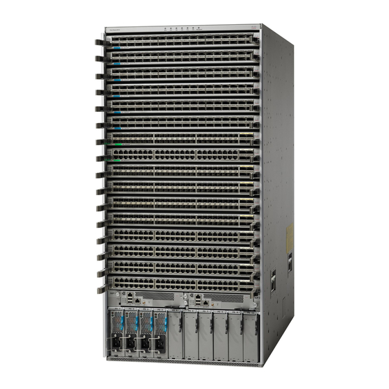
- Page 14 The following figure shows the hardware features seen from the front of the chassis. 2 vertical mounting 3-kW AC, Universal brackets used to mount AC/DC, or DC power the chassis onto a rack supplies (AC power supplies shown) Cisco Nexus 9516 NX-OS Mode Switch Hardware Installation Guide...
- Page 15 The following figure shows the hardware features seen from the rear of the chassis (one fan tray has been removed to show the fabric modules behind the fan trays). Cisco Nexus 9516 NX-OS Mode Switch Hardware Installation Guide...
- Page 16 Chassis handles (used with up to 2 behind each only for positioning the fan tray) chassis on the bottom support rails—do not use these handles for lifting the chassis) System controllers (2) Cisco Nexus 9516 NX-OS Mode Switch Hardware Installation Guide...
-
Page 17: Preparing The Site
This condition can also cause sealed components with internal pressure, such as electrolytic capacitors, to fail or to perform at a reduced efficiency. Cisco Nexus 9516 NX-OS Mode Switch Hardware Installation Guide... -
Page 18: Dust And Particulate Requirements
The wiring is unlikely to emit radio interference if you use a twisted-pair cable with a good distribution of grounding conductors. If you exceed the recommended distances, use a high-quality twisted-pair cable with one ground conductor for each data signal when applicable. Cisco Nexus 9516 NX-OS Mode Switch Hardware Installation Guide... -
Page 19: Shock And Vibration Requirements
Calculate the power that is required for operations (available power) and redundancy (reserve power), then you can plan for the required number of input power receptacles. The power receptacles will be within reach of the switch location. Cisco Nexus 9516 NX-OS Mode Switch Hardware Installation Guide... - Page 20 36-port 100-Gigabit Ethernet QSFP28 line card (N9K-X9736C-EX) 632 W 792 W – 36-port 100-Gigabit Ethernet QSFP28 line card (N9K-X9736C-FX) 607 W 720 W – 36-port 40-Gigabit Ethernet QSFP28 line card (N9K-X9736Q-FX) 571 W 684 W Cisco Nexus 9516 NX-OS Mode Switch Hardware Installation Guide...
- Page 21 82.5 A and you are able to use up to 80 percent of the capacity of a circuit breaker, you use the following formula to calculate the minimum amperage that is required of the circuit breaker: (82.5 A)/ (80% or 0.80) = 103.1 amps Cisco Nexus 9516 NX-OS Mode Switch Hardware Installation Guide...
- Page 22 3-kW DC power supplies You provide four 6-gauge wires (recommended) and cuts that wire to the required length. We provide four 6-gauge lugs to connect those wires to the DC power supply. Cisco Nexus 9516 NX-OS Mode Switch Hardware Installation Guide...
-
Page 23: Rack And Cabinet Requirements
• Power cords for the 3-kW Universal AC power supplies are 14 feet (4.27 m) long. Note The power cables for the 3-kW DC power supply are provided by and sized you. Cisco Nexus 9516 NX-OS Mode Switch Hardware Installation Guide... -
Page 24: Clearance Requirements
Vertical rack-mount posts Minimum clearance and rails required for module handles (up to 6 inches [15.24 cm] recommended for optimal airflow) when using cabinet doors Cisco Nexus 9516 NX-OS Mode Switch Hardware Installation Guide... - Page 25 Side clearance, that is required for older line card handle rotation (not required for the current line cards which have handles that rotate differently). No right-side clearance required (no airflow on the right side). Cisco Nexus 9516 NX-OS Mode Switch Hardware Installation Guide...
- Page 26 Preparing the Site Clearance Requirements Cisco Nexus 9516 NX-OS Mode Switch Hardware Installation Guide...
-
Page 27: Installing A Chassis
Switch Modules, on page 98. This circuit must include receptacles that match your local and national requirements and match the needs of the power cable that is used with the power supply unit. Cisco Nexus 9516 NX-OS Mode Switch Hardware Installation Guide... -
Page 28: Inspecting The New Switch
• For four modules, they must be in slots FM 2, FM 3, FM 4, and FM 6. • For five modules, they must be in slots FM 2, FM 3, FM 4, FM 5, and FM 6. Cisco Nexus 9516 NX-OS Mode Switch Hardware Installation Guide... -
Page 29: Installing The Bottom-Support Rails
• 3.15-kW Dual Input Universal AC/DC power supply (N9K-PUV2-3000W-B) • 3-kW DC power supply (N9K-PDC-3000W-B) • Rack Mount kit • Rack mount kit for the Cisco Nexus 9516 (N9K-C9500-RMK) chassis • Bottom-support rails (2) • M6 mounting screws (20) • 10-32 mounting screws (20) •... - Page 30 21 RU (36.7 inches [93.4 cm]) of vertical space above the rails to install the chassis, see the following figure. You can expand the rail so that its mounting brackets are spaced between 24 to 32 inches (61.0 to 81.3 cm). Cisco Nexus 9516 NX-OS Mode Switch Hardware Installation Guide...
- Page 31 3/4 inch screws for each end of the rail (using a total of 6 screws for the rail as shown in the following figure) and tighten each screw to 40 in-lbs (4.5 N.m) of torque. Cisco Nexus 9516 NX-OS Mode Switch Hardware Installation Guide...
-
Page 32: Installing A Chassis In A Rack Or Cabinet
You can remove modules from the chassis to make the chassis easier to move. Before you begin • You have fully installed a rack or cabinet (see Installing a Rack or Cabinet). Cisco Nexus 9516 NX-OS Mode Switch Hardware Installation Guide... - Page 33 • When mounting this unit in a partially filled rack, load the rack from the bottom to the top with the heaviest component at the bottom of the rack. • If the rack is provided with stabilizing devices, install the stabilizers before mounting or servicing the unit in the rack. Cisco Nexus 9516 NX-OS Mode Switch Hardware Installation Guide...
- Page 34 Push only the lower front sides of the chassis—do not push any modules and do not use any module handles to move the chassis. Cisco Nexus 9516 NX-OS Mode Switch Hardware Installation Guide...
- Page 35 Use two people to push the chassis all the way onto the rack or cabinet. You have pushed the chassis all the way when its two vertical mounting brackets come in contact with the vertical rails on the rack or cabinet. Cisco Nexus 9516 NX-OS Mode Switch Hardware Installation Guide...
- Page 36 To reinstall the fan trays, see t_n95xx_install_fan_tray.xml What to do next After the chassis is secured to the rack, you can ground the switch (see Grounding the Chassis, on page 27). Cisco Nexus 9516 NX-OS Mode Switch Hardware Installation Guide...
-
Page 37: Grounding The Chassis
Verify that the ground wire is securely attached to the grounding lug by attempting to pull the wire out of the crimped lug. Chassis grounding pad 2 M4 screws are used to secure the grounding lug to the chassis Cisco Nexus 9516 NX-OS Mode Switch Hardware Installation Guide... -
Page 38: Starting Up The Switch
Cover each open slot with a power supply slot blank to preserve the designed airflow, until you add more power supplies. You turn on the switch when you connect its power supplies to one or two power sources. Cisco Nexus 9516 NX-OS Mode Switch Hardware Installation Guide... -
Page 39: Connecting A 3-Kw Ac Power Supply To An Ac Power Source
Verify that the Output Power LED turns on and becomes green. What to do next After you finish connecting the power supplies to the power source and the power supplies are operating, you connect the switch to the network. Cisco Nexus 9516 NX-OS Mode Switch Hardware Installation Guide... -
Page 40: Connecting A 3-Kw Universal Ac/Dc Power Supply To A Dc Power Source
• The power supplies must be close enough to be connected to the DC power source using the customer-provided power cables. • Four 6-AWG lugs that are provided with the switch. • Customer-provided equipment and tools must include the following: Cisco Nexus 9516 NX-OS Mode Switch Hardware Installation Guide... - Page 41 Use a torque screwdriver to unscrew the three screws that are on the cover of the terminal box. the cover is located on the front of the power supply and lifts off the cover as shown in the following figure. Cisco Nexus 9516 NX-OS Mode Switch Hardware Installation Guide...
- Page 42 Turn the power switch on the power supply to ON (labeled 1 on the power supply). The LEDs flash and then the OK LED turns on (green) in addition to the Input LEDs. Cisco Nexus 9516 NX-OS Mode Switch Hardware Installation Guide...
- Page 43 Installing a Chassis Connecting a 3-kW DC Power Supply to a DC Power Source What to do next You are ready to connect the switch to the network. Cisco Nexus 9516 NX-OS Mode Switch Hardware Installation Guide...
- Page 44 Installing a Chassis Connecting a 3-kW DC Power Supply to a DC Power Source Cisco Nexus 9516 NX-OS Mode Switch Hardware Installation Guide...
-
Page 45: Connecting The Switch To The Network
• Do not touch the ends of connectors. Touching the ends can leave fingerprints and cause other contamination. Cisco Nexus 9516 NX-OS Mode Switch Hardware Installation Guide... -
Page 46: Connecting A Console To The Switch
You make this local management connection between the asynchronous serial port on a supervisor module and a console device capable of asynchronous transmission. Typically, you can use a computer terminal as the console device. On the supervisor modules, you use the console serial port. Cisco Nexus 9516 NX-OS Mode Switch Hardware Installation Guide... -
Page 47: Connecting The Management Interface
The supervisor management port (MGMT ETH) provides out-of-band management, which enables you to use the command-line interface (CLI) to manage the switch by its IP address. This port uses a 10/100/1000 Ethernet connection with an RJ-45 interface. Cisco Nexus 9516 NX-OS Mode Switch Hardware Installation Guide... -
Page 48: Creating The Initial Switch Configuration
To connect the switch to the network, you can use the default choices for each configuration except the IP address, which you must provide. You can perform the other configurations later as described in the Cisco Nexus 9000 Series NX-OS Fundamentals Configuration Guide. - Page 49 Enter the IP address for the management interface. The software asks for the Mgmt0 IPv4 netmask. Step 6 Enter a network mask for the management interface. The software asks if you need to edit the configuration. Cisco Nexus 9516 NX-OS Mode Switch Hardware Installation Guide...
-
Page 50: Connecting Interface Ports
You can disconnect a BASE-T (copper) port from the network by removing a copper network interface cable with RJ-45 connectors from the line card interface port. Before you begin Follow the ESD-preventative protocol, such as wearing a grounded ESD wrist strap, whenever handling electronic components. Cisco Nexus 9516 NX-OS Mode Switch Hardware Installation Guide... -
Page 51: Connecting An Optical Port To The Network
If using an optical cable, insert the optical cable into the installed transceiver. Disconnecting Optical Ports from the Network When removing fiber-optic transceivers, you must remove the fiber-optic cables from a transceiver before removing the transceiver from the port. Cisco Nexus 9516 NX-OS Mode Switch Hardware Installation Guide... -
Page 52: Maintaining Transceivers And Optical Cables
• Inspect routinely for dust and damage. If you suspect damage, clean and then inspect fiber ends under a microscope to determine if damage has occurred. Cisco Nexus 9516 NX-OS Mode Switch Hardware Installation Guide... -
Page 53: Managing The Switch
But does not display information for modules that do not respond to those commands, such as blank modules that cover empty slots to manage airflow. Cisco Nexus 9516 NX-OS Mode Switch Hardware Installation Guide... -
Page 54: Displaying The Backplane And Serial Number Information
The switch detects a module failure upon initialization and automatically attempts to power-cycle the module three times. After the third attempt, the module powers down. The switch is ready to be configured. Cisco Nexus 9516 NX-OS Mode Switch Hardware Installation Guide... -
Page 55: Displaying Temperatures For A Module
• Major temperature threshold—When a major threshold is exceeded, a major alarm occurs and the following actions occur: • For sensors 1, 3, and 4 (outlet and on-board sensors), the following actions occur: • Displays system messages. • Sends Call Home alerts (if configured). Cisco Nexus 9516 NX-OS Mode Switch Hardware Installation Guide... - Page 56 Temperature: -------------------------------------------------------------------- Module Sensor MajorThresh MinorThres CurTemp Status (Celsius) (Celsius) (Celsius) -------------------------------------------------------------------- TD2-1 TD2-2 TD2-3 VRM-1 VRM-2 VRM-3 TD2-1 TD2-2 VRM-1 VRM-2 OUTLET INLET OUTLET INLET Cisco Nexus 9516 NX-OS Mode Switch Hardware Installation Guide...
-
Page 57: Connecting To A Module
This command reports on only software-controlled modules, such as supervisors, system controllers, line cards, fabric modules, fan trays, and power supplies. It reports on modules that are not controlled by software, such as blank modules installed in empty slots to control airflow. Cisco Nexus 9516 NX-OS Mode Switch Hardware Installation Guide... -
Page 58: Saving The Module Configuration
It does not work with modules that are not controlled by software, such as blank modules installed in empty slots to control airflow. Cisco Nexus 9516 NX-OS Mode Switch Hardware Installation Guide... -
Page 59: Purging A Nonfunctioning Module From The Running Configuration
To display the power usage information for the entire switch, use the show environment power command. This command shows the power usage for the power consuming modules that are installed in the switch. Cisco Nexus 9516 NX-OS Mode Switch Hardware Installation Guide... -
Page 60: Reload A Module
This command will reload module 4. Proceed[y/n]? [n] y reloading module 4 ... switch(config)# Rebooting a Switch You can reboot or reload the switch by using the reload command without any options. Cisco Nexus 9516 NX-OS Mode Switch Hardware Installation Guide... -
Page 61: Overview Of Supervisor Modules
If the switch has just one supervisor, you can install the new supervisor in the open supervisor slot during operations. You can make that supervisor active after the installation. Cisco Nexus 9516 NX-OS Mode Switch Hardware Installation Guide... - Page 62 • sup-active refers to the active supervisor module—relative to the slot that contains the active supervisor module. • sup-standby refers to the standby supervisor module—relative to the slot that contains the standby supervisor module. Cisco Nexus 9516 NX-OS Mode Switch Hardware Installation Guide...
-
Page 63: Overview Of Power Modes
3 kW. If you have two power grids, you use grid A to power two 3-kW power supplies that provide the available power for the switch. And You use grid B to power the other two 3-kW power supplies that provide the reserve power in case grid A fails. Cisco Nexus 9516 NX-OS Mode Switch Hardware Installation Guide... -
Page 64: Power Mode Configuration Guidelines
3.0 kW — Available power is less than the power requirement for the switch. You cannot power the entire switch (some of the line cards will not be able to power up). Cisco Nexus 9516 NX-OS Mode Switch Hardware Installation Guide... - Page 65 3.0 kW each, provide enough power (6.0 kW) to meet the switch requirements (5.2 kW), so the entire switch powers up. The following table shows the results for each scenario. Cisco Nexus 9516 NX-OS Mode Switch Hardware Installation Guide...
- Page 66 (output from the other power supply). The available power (3.0 kW) does not meet the switch requirements (5.2 kW), so most of the modules power up but some of the line cards will not be able to power up. • Scenario 2—Adding two 3-kW power supplies Cisco Nexus 9516 NX-OS Mode Switch Hardware Installation Guide...
-
Page 67: Setting The Power Mode
• Slots PS 6 to PS 10 must be connected to another grid (Grid B) Setting the Power Mode You can configure the power supply mode by using the power redundancy-mode command. Cisco Nexus 9516 NX-OS Mode Switch Hardware Installation Guide... -
Page 68: Overview Of Fan Trays
• If you remove more than one fan tray at a time, the switch can operate up to three minutes before shutting down. To prevent a shutdown, remove only one fan tray at a time. Cisco Nexus 9516 NX-OS Mode Switch Hardware Installation Guide... -
Page 69: Displaying The Status For The Fan Trays
There must be a functioning fabric module installed behind that fan tray in order for the fan tray to be powered up. Cisco Nexus 9516 NX-OS Mode Switch Hardware Installation Guide... - Page 70 Managing the Switch Displaying the Status for the Fan Trays Cisco Nexus 9516 NX-OS Mode Switch Hardware Installation Guide...
-
Page 71: Replacing Or Installing Modules, Fan Trays, And Power Supplies
Verify that the grounding cable is attached to the facility earth ground. Installing or Replacing a Supervisor Module The switch can operate with one or two supervisor modules that are installed in the chassis. Cisco Nexus 9516 NX-OS Mode Switch Hardware Installation Guide... - Page 72 If you are replacing a module that is currently in the chassis, remove the existing module from the chassis by following these steps: a) Disconnect and label the following cables from the module: Cisco Nexus 9516 NX-OS Mode Switch Hardware Installation Guide...
- Page 73 Align the back of the module to the guides in the open supervisor slot and slide the module all the way into the slot. See the following figure. The module stops when its front is about 0.25 inches (0.6 cm) outside the front of the chassis. Cisco Nexus 9516 NX-OS Mode Switch Hardware Installation Guide...
-
Page 74: Upgrading A Supervisor Module
You can upgrade supervisor modules by using the hot swap method. The upgrade path for your active supervisor module can be found in the following table: Active Supervisor Allowed Upgrade Supervisor A Supervisor A+ Supervisor A Supervisor B+ Cisco Nexus 9516 NX-OS Mode Switch Hardware Installation Guide... -
Page 75: Installing Or Replacing A System Controller Module
• Prepare an antistatic surface or packing materials for each module that you remove from the chassis. Step 1 Open the packaging for the new system controller module and inspect the module for damage. If the module is damaged, alert the Technical Assistance Center (TAC). Cisco Nexus 9516 NX-OS Mode Switch Hardware Installation Guide... - Page 76 Hold the front of the module with one hand and place your other hand under the module to support it. c) Align the back of the module to the guides in the open controller slot and slide the module all the way into the slot. Cisco Nexus 9516 NX-OS Mode Switch Hardware Installation Guide...
-
Page 77: Installing Or Replacing A Line Card
• Prepare an antistatic surface or packing materials for each module that you remove from the chassis. Step 1 Open the packaging for the new line card and inspect the module for damage. If the module is damaged, contact the Technical Assistance Center (TAC). Cisco Nexus 9516 NX-OS Mode Switch Hardware Installation Guide... - Page 78 Pull both levers to slide the line card out of its slot in the chassis as shown in the following figure. Pull both levers to remove the line card from the chassis. Cisco Nexus 9516 NX-OS Mode Switch Hardware Installation Guide...
- Page 79 Attach each interface cable to the appropriate port on the line card. Use the label on each cable to determine which port each cable attaches to. f) Verify that the line card LEDs turn on and appear as follows: • The Status (STS or STA) LED turns on and becomes green. Cisco Nexus 9516 NX-OS Mode Switch Hardware Installation Guide...
-
Page 80: Replacing A Fan Tray
If the module is damaged, contact the Technical Assistance Center (TAC) and wait until you have an undamaged fan tray to install. Step 2 Unscrew the four captive screws on the front of the fan tray until each screw is free of the chassis. See the following figure. Cisco Nexus 9516 NX-OS Mode Switch Hardware Installation Guide... - Page 81 Hold both handles on the front of the fan tray with both of your hands and pull the fan tray out of the slot. Step 4 Set the fan tray on antistatic material or inside an antistatic bag. Cisco Nexus 9516 NX-OS Mode Switch Hardware Installation Guide...
-
Page 82: Installing A Fan Tray
Use both of your hands to hold the two handles on the front of the fan tray that you are installing. Hold the 2 fan tray handles with both hands. Screw in 4 captive screws and tighten each screw to 8 in-lb (0.9 N·m) of torque. Cisco Nexus 9516 NX-OS Mode Switch Hardware Installation Guide... -
Page 83: Replacing A Fabric Module
• For five FM-E or FM-E2 modules, they must be in Slots FM 2, FM 3, FM 4, FM 5, and FM 6. • For six modules, they are in slots FM 1, FM 2, FM 3, FM 4, FM 5, and FM 6 Cisco Nexus 9516 NX-OS Mode Switch Hardware Installation Guide... -
Page 84: Removing A Fabric Module
Remove the fan tray that covers the fabric module by following these steps: a) Unscrew the four captive screws on the front of the fan tray until each screw is free of the chassis. See Callout 1 in the following figure. Cisco Nexus 9516 NX-OS Mode Switch Hardware Installation Guide... - Page 85 Verify that the Fabric LED for the slot that you specified turns off. Step 4 Remove the fabric module that you are replacing by following these steps: Cisco Nexus 9516 NX-OS Mode Switch Hardware Installation Guide...
- Page 86 See Callout 2 in the previous figure. c) With each of the two handles in your two hands, pull the module a couple of inches (about 5 cm) out of the slot. See the following figure. Cisco Nexus 9516 NX-OS Mode Switch Hardware Installation Guide...
- Page 87 Place one hand under the fabric module to support its weight. Place your other hand on the front of the module, and slide the module out of the slot. f) Rotate the module 90 degrees and lay it flat on an antistatic surface or in an antistatic bag. Cisco Nexus 9516 NX-OS Mode Switch Hardware Installation Guide...
-
Page 88: Installing A Fabric Module
Callouts 1 and 2 in the following figure. Be sure that the locking posts on the top and bottom of the chassis rotate into the module so that the module can slide fully into the slot. See Callout 3 of the following figure. Cisco Nexus 9516 NX-OS Mode Switch Hardware Installation Guide... - Page 89 Fit the guide rails on the top of the module into the track on the top of the slot. Make sure that the guide bar on the bottom of the module goes into the module guide at the bottom of the slot. Cisco Nexus 9516 NX-OS Mode Switch Hardware Installation Guide...
- Page 90 Reinstall the fan module over the replaced fabric module by following these steps: a) Use both of your hands to hold the two handles on the front of the fan tray that you are installing. Cisco Nexus 9516 NX-OS Mode Switch Hardware Installation Guide...
- Page 91 Slide the fan tray all the way into the slot until the front of the fan tray touches the chassis. Make sure that the four captive screws on the front of the fan tray align with the four screw holes in the chassis. Cisco Nexus 9516 NX-OS Mode Switch Hardware Installation Guide...
-
Page 92: Installing Or Replacing Power Supplies
Do not operate the system unless all cards, faceplates, front covers, and rear covers are in place. You can install or replace any of the following Cisco Nexus 9500 Series power supplies in this switch: • 3-kW AC Power Supply •... - Page 93 Ensure that the power supply is not connected to an AC power source. If it is connected to a power source, remove the power cable from the power supply and wait at least five seconds before doing the next step. Cisco Nexus 9516 NX-OS Mode Switch Hardware Installation Guide...
- Page 94 • If you are using the n+n redundancy mode, you must connect the power cable to the same power source as used by the other power supplies in the same set of power supply slots in the chassis. The power cables for slots 1 Cisco Nexus 9516 NX-OS Mode Switch Hardware Installation Guide...
-
Page 95: Installing Or Replacing A 3-Kw Universal Ac/Dc Power Supply
If the FAULT LED is on and the color is amber, that indicates that the power source connection has been broken. 4. Remove the power cable plug from the power supply receptacle. Cisco Nexus 9516 NX-OS Mode Switch Hardware Installation Guide... - Page 96 Slide the handle on the middle of the power supply release lever toward the end of the module and rotate the lever away from the front of the power supply while pushing the power supply all the way into the chassis. See the following figure. Cisco Nexus 9516 NX-OS Mode Switch Hardware Installation Guide...
- Page 97 If you connected the power supply to a DC power source do the following: 1. Turn on the circuit breaker for the DC power source. 2. Turn on the power supply by setting the power switch to on (1). Cisco Nexus 9516 NX-OS Mode Switch Hardware Installation Guide...
-
Page 98: Installing Or Replacing A 3.15-Kw Dual Input Universal Ac/Dc Power Supply
3.15KW with either one or two input power lines operating. The HVAC/HVDC power supply provides n+n or n+x line redundancy mode in a single power supply for the Cisco Nexus 9500 Series switches. The HVAC/HVDC power supply accepts 200–240VAC or 240/380VDC input power. -
Page 99: Installing Or Replacing A 3-Kw Dc Power Supply
If you are replacing a power supply that is currently in the chassis, remove the existing module from the chassis by following these steps: a) Turn off the power to the power supply that you are replacing as follows: Cisco Nexus 9516 NX-OS Mode Switch Hardware Installation Guide... - Page 100 1. Slide the middle of the ejector lever toward the end of the lever and rotate the lever away from the chassis. The power supply unlocks from the chassis and moves out slightly. Cisco Nexus 9516 NX-OS Mode Switch Hardware Installation Guide...
- Page 101 Fully rotate the release lever away from the front Make sure that the other end of the lever grabs the of the module. front of the chassis to push the module onto the connectors inside the slot. Cisco Nexus 9516 NX-OS Mode Switch Hardware Installation Guide...
- Page 102 2. Use a torque screwdriver to unscrew three screws on the cover for the terminal box that is located on the front of the power supply. Then lift off the cover as shown in the following figure. Remove 3 screws from the Remove the cover. safety cover. Cisco Nexus 9516 NX-OS Mode Switch Hardware Installation Guide...
-
Page 103: Migrating The Switch From Using 40-Gigabit Line Cards To Using 100-Gigabit -Ex/-Fx Line Cards
Replace each of the older line cards (N9K-X94xx, N9K-X95xx, or N9K-X96xx) with an N9K-97xxx-EX or N9K-X97xx-FX line card as explained in the Installing or Replacing a Line Card, on page You have the option of hot swapping these line cards during operations. Note Cisco Nexus 9516 NX-OS Mode Switch Hardware Installation Guide... - Page 104 WARNING! there is unsaved configuration!!! This command will reboot the system. (y/n)? [n] Step 6 During the bootup, configure the switch by using the setup option. For configuration information, see the Cisco Nexus 9000 Series NX-OS Fundamentals Configuration Guide. Step 7 Copy the old configuration from the bootflash to the new configuration by using the copy command.
-
Page 105: System Specifications
Without mounting Inside chassis: 20.67 1.75 inches (4.4 cm) brackets: 7.0 inches inches (52.5 cm) (17.78 cm) Ejector levers outside With mounting brackets: chassis: 0.75 inches (1.9 8.0 inches (20.32 cm) Cisco Nexus 9516 NX-OS Mode Switch Hardware Installation Guide... -
Page 106: Weights For The Chassis, Modules, Fan Trays, And Power Supplies
6.0 lb (2.72 kg) – Supervisor B+ module (N9K-SUP-B+) 5.3 lb (2.39 kg) — Line cards that the N9K-C9516-FM fabric modules support – 8-port 100-Gigabit Ethernet CFP2 line card (N9K-X9408PC-CFP2) 13.05 lb (5.92 kg) Cisco Nexus 9516 NX-OS Mode Switch Hardware Installation Guide... - Page 107 3-kW Universal AC/DC Power Supply (N9K-PUV-3000W-B) 5.9 lb (2.67 kg) – 3.15-kW Dual Input Universal AC/DC Power Supply (N9K-PUV2-3000W-B) 5.9 lb (2.67 kg) – 3-kW DC Power Supply (N9K-PDC-3000W-B) 6.4 lb (2.9 kg) Cisco Nexus 9516 NX-OS Mode Switch Hardware Installation Guide...
-
Page 108: Power Specifications
12,000 W 27,000 W 24,000 W 12,000 W 30,000 W 27,000 W 15,000 W Power Supply Specifications The following subtopics list the specifications for each power supply that this switch supports. Cisco Nexus 9516 NX-OS Mode Switch Hardware Installation Guide... -
Page 109: 3000-W Ac Power Supply Specifications
3000-W Dual Input Universal AC/DC Power Supply Specifications Property Specification Power 3150 W Input Voltage 180 to 305 VAC or 192 to 400 VDC or Frequency 50 to 60 Hz Efficiency 90% or greater (20 to 100% load) Cisco Nexus 9516 NX-OS Mode Switch Hardware Installation Guide... -
Page 110: 3000-W Dc Power Supply Specifications
The following subtopics list the specifications for supported power cables. 3-kW AC Power Cable Specifications Locale Power Cord Part Number Cord Set Rating Power Cord Illustration Australia and New Zealand CAB-AC-16A-AUS 16 A, 250 VAC Cisco Nexus 9516 NX-OS Mode Switch Hardware Installation Guide... - Page 111 CAB-AC-16A-CH 16 A, 250 VAC Italy CAB-AC-16A-SG-IT 16 A, 250 VAC North America CAB-AC-20A-SG-US 16 A, 250 VAC Continental Europe CAB-AC-2500W-EU 16 A, 250 VAC International CAB-AC-2500W-INT 16 A, 250 VAC Cisco Nexus 9516 NX-OS Mode Switch Hardware Installation Guide...
- Page 112 16 A, 250 VAC (locking) 200-240 VAC operation Power distribution unit (PDU) CAB-C19-CBN 16 A, 250 VAC Switzerland CAB-ACS-16 16 A, 250 VAC North America CAB-L520P-C19-US NEMA L5-20 to IEC-C19 6 feet (1.8 m) Cisco Nexus 9516 NX-OS Mode Switch Hardware Installation Guide...
-
Page 113: 3-Kw Universal Ac/Dc Power Cable Specifications
Each 3-kW DC power supply requires four customer-supplied power cables (two negative cables and two positive cables). We recommend using six gauge cables. Cisco supplies 6-gauge lugs for connections to the power supply. You supply the connectors that are required to connect the cables to the DC power source. - Page 114 System Specifications 3-kW DC Power Supply Power Cord Specifications Cisco Nexus 9516 NX-OS Mode Switch Hardware Installation Guide...
-
Page 115: Leds
Line cards (I/O modules) are all operational. Amber Check Line Card LEDs, on page 108 for more information. Power supplies are all operational. Green Amber Check the Power Supply LEDs for more information. Cisco Nexus 9516 NX-OS Mode Switch Hardware Installation Guide... -
Page 116: System Controller Leds
The following table describes the possible states for each of these LEDs. Color Status Flashing blue The operator has activated this LED to identify this module in the chassis. This module is not being identified. Cisco Nexus 9516 NX-OS Mode Switch Hardware Installation Guide... -
Page 117: Fan Tray Leds
The fabric modules behind this fan tray are operational. Green Amber At least one fabric module behind this fan tray is not operating. No power is going to the fabric module behind this fan tray. Cisco Nexus 9516 NX-OS Mode Switch Hardware Installation Guide... -
Page 118: Fabric Module Leds
LED. The following table describes the possible states for each of these LEDs. Color Status Flashing blue The operator has activated this LED to identify this module in the chassis. This LED is not being used. Cisco Nexus 9516 NX-OS Mode Switch Hardware Installation Guide... -
Page 119: Power Supply Leds
The power supply may not be properly installed in the chassis. Either all the installed power supplies are not receiving power or an uninstalled power supply is not receiving power. Cisco Nexus 9516 NX-OS Mode Switch Hardware Installation Guide... - Page 120 Power supply is installed without a connection to a power source. (10 seconds) then amber Amber Power supply failure—possibly one of the following conditions: • Over voltage • Over current • Over temperature • Power supply fan failure Cisco Nexus 9516 NX-OS Mode Switch Hardware Installation Guide...
-
Page 121: Appendix C Additional Kits
• M6 x 19-mm Phillips screws (20) • Adjustable bottom-support rails RJ-45 rollover cable DB9F/RJ-45F PC terminal Ground lug kit 1 kit • Two-hole lug (1) • M4 x 8-mm Phillips pan-head screws (2) Cisco Nexus 9516 NX-OS Mode Switch Hardware Installation Guide... - Page 122 Instructions Note If you do not receive a part that is listed in this document, contact Cisco Technical Support at this URL: http://www.cisco.com/warp/public/687/Directory/DirTAC.shtml. If you purchased this product through a Cisco reseller, you may receive contents in your kit, such as documentation, hardware, and power cables.
- Page 123 • CAB-AC-20A-SG-C20—Jumper, 250 VAC 20 A, IEC C20/Saf-D-Grid, North America • CAB-HV-25A-SG-US1—power cord, 277 VAC/240 VDC/380 VDC 25 A, Saf-D-Grid/Saf-D-Grid, North America • CAB-HV-25A-SG-US2—power cord, 277 VAC/240 VDC/380 VDC 25 A, Ring Terminal/Saf-D-Grid, North America Cisco Nexus 9516 NX-OS Mode Switch Hardware Installation Guide...
- Page 124 Additional Kits Additional Kits Cisco Nexus 9516 NX-OS Mode Switch Hardware Installation Guide...
Need help?
Do you have a question about the Nexus 9516 and is the answer not in the manual?
Questions and answers