Table of Contents
Advertisement
Quick Links
Advertisement
Table of Contents

Related Manuals for Cisco Nexus 9516


Summary of Contents for Cisco Nexus 9516
- Page 1 Cisco Nexus 9516 ACI-Mode Switch Hardware Installation Guide First Published: 2015-06-14 Last Modified: 2019-03-28 Americas Headquarters Cisco Systems, Inc. 170 West Tasman Drive San Jose, CA 95134-1706 http://www.cisco.com Tel: 408 526-4000 800 553-NETS (6387) Fax: 408 527-0883...
- Page 2 Cisco and the Cisco logo are trademarks or registered trademarks of Cisco and/or its affiliates in the U.S. and other countries. To view a list of Cisco trademarks, go to this URL: https://www.cisco.com/c/en/us/about/legal/trademarks.html. Third-party trademarks mentioned are the property of their respective owners. The use of the word partner does not imply a partnership relationship between Cisco and any other company.
-
Page 3: Table Of Contents
Shock and Vibration Requirements Grounding Requirements Planning for Power Requirements Rack and Cabinet Requirements Clearance Requirements C H A P T E R 3 Installing a Chassis Installing a Rack or Cabinet Cisco Nexus 9516 ACI-Mode Switch Hardware Installation Guide... - Page 4 Installing or Replacing a System Controller Module Installing or Replacing a Line Card Replacing a Fan Tray Removing a Fan Tray Installing a Fan Tray Replacing a Fabric Module Removing a Fabric Module Cisco Nexus 9516 ACI-Mode Switch Hardware Installation Guide...
- Page 5 Chassis LEDs System Controller LEDs Supervisor Module LEDs Fan Tray LEDs Fabric Module LEDs Line Card LEDs Power Supply LEDs A P P E N D I X C Additional Kits Accessory Kit Cisco Nexus 9516 ACI-Mode Switch Hardware Installation Guide...
- Page 6 Contents Cisco Nexus 9516 ACI-Mode Switch Hardware Installation Guide...
-
Page 7: Preface
Braces and a vertical bar within square brackets indicate a required choice within an optional element. Indicates a variable for which you supply values, in context where italics variable cannot be used. Cisco Nexus 9516 ACI-Mode Switch Hardware Installation Guide... -
Page 8: Related Documentation
• Cisco Application Centric Infrastructure Fundamentals Guide • Cisco APIC Getting Started Guide • Cisco ACI Virtualization Guide • Cisco APIC REST API User Guide • Cisco APIC Command Line Interface User Guide Cisco Nexus 9516 ACI-Mode Switch Hardware Installation Guide viii... - Page 9 • Cisco ACI System Messages Reference Guide • Cisco APIC Layer 4 to Layer 7 Services Deployment Guide • Cisco APIC Layer 4 to Layer 7 Device Package Development Guide • Cisco APIC Layer 4 to Layer 7 Device Package Test Guide •...
-
Page 10: Documentation Feedback
What's New in Cisco Product Documentation, at: https://www.cisco.com/warp/public/687/Directory/DirTAC.shtml. Subscribe to What's New in Cisco Product Documentation, which lists all new and revised Cisco technical documentation as an RSS feed and delivers content directly to your desktop using a reader application. The RSS feeds are a free service. -
Page 11: Overview
See the following table for the required fabric module types and quantities that are required for maximum bandwidth. Table 1: Supported Fabric Modules and Line Cards Fabric Module Fabric Modules Supported Line Cards Required for Maximum Bandwidth N9K-C9516-FM N9K-X9736PQ Cisco Nexus 9516 ACI-Mode Switch Hardware Installation Guide... - Page 12 Fabric Modules Supported Line Cards Required for Maximum Bandwidth N9K-C9516-FM-E2 N9K-X9732C-EX N9K-X9736C-FX N9K-X9736Q-FX Table 2: FM-25 Feature Support Matrix for Cisco Nexus 9000 Series line cards and fabric modules Line cards X9736PQ X9736Q-FX X9732C-EX X9736C-FX Fabric modules C9516-FM-E-E2 Note The fabric modules must be installed in specific slots as follows (installing fabric modules in other slots can cause a module mismatch condition): •...
- Page 13 • Cisco Nexus 9500 Series 3-kW AC power supply (N9K-PAC-3000W-B) • Cisco Nexus 9500 Series 3-kW Universal AC/DC power supply (N9K-PUV-3000W-B) • Cisco Nexus 9500 Series 3.15-kW Dual Input Universal AC/DC power supply (N9K-PUV2-3000W-B) • Cisco Nexus 9500 Series 3-kW (-48 V) DC power supply (N9K-PDC-3000W-B) Note The switch can be powered by a mix of AC, DC, HVAC/HVDC power sources.
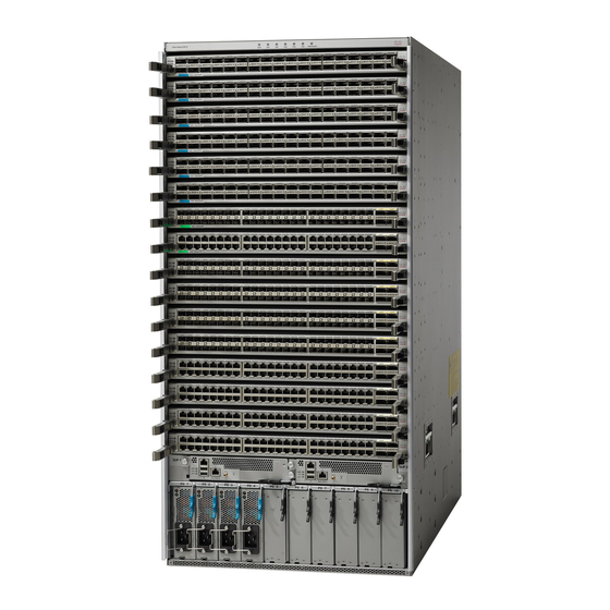
- Page 14 I/O modules (up to 16) Chassis LEDs Supervisor modules (1 or Chassis handles (used only for positioning the chassis on the bottom support rails—do not use these handles for lifting the chassis) Cisco Nexus 9516 ACI-Mode Switch Hardware Installation Guide...
- Page 15 Fabric modules (up to 6 Chassis handles (used with up to 2 behind each only for positioning the fan tray) chassis on the bottom support rails—do not use these handles for lifting the chassis) Cisco Nexus 9516 ACI-Mode Switch Hardware Installation Guide...
- Page 16 Overview Overview System controllers (2) Cisco Nexus 9516 ACI-Mode Switch Hardware Installation Guide...
-
Page 17: Preparing The Site
Altitude Requirements Altitude rating is based on power supply installed; see critical components list in the system CB report for altitude rating. Cisco Nexus 9516 ACI-Mode Switch Hardware Installation Guide... -
Page 18: Dust And Particulate Requirements
The wiring is unlikely to emit radio interference if you use a twisted-pair cable with a good distribution of grounding conductors. If you exceed the recommended distances, use a high-quality twisted-pair cable with one ground conductor for each data signal when applicable. Cisco Nexus 9516 ACI-Mode Switch Hardware Installation Guide... -
Page 19: Shock And Vibration Requirements
To plan for the power requirements of a switch, you must determine each of the following: • Power requirements for all the switch components • Minimum number of power supplies required to power the components that are installed in the switch. Cisco Nexus 9516 ACI-Mode Switch Hardware Installation Guide... - Page 20 For example, if you are installing a switch with maximum consumption of 6694 W, you need three power supplies (6694 W / 3000 W = 2.23 [rounded up to three power supplies]) to operate the switch and its modules. Cisco Nexus 9516 ACI-Mode Switch Hardware Installation Guide...
- Page 21 (for a total of four 3-kW power supplies used for available and reserve power). Step 5 Be sure that the power source circuits are dedicated to the switch and not to other electrical equipment. Cisco Nexus 9516 ACI-Mode Switch Hardware Installation Guide...
-
Page 22: Rack And Cabinet Requirements
You can install the following types of racks or cabinets for your switch: • Standard perforated cabinets • Solid-walled cabinets with a roof fan tray (bottom-to-top cooling) • Standard open four-post Telco racks Cisco Nexus 9516 ACI-Mode Switch Hardware Installation Guide... - Page 23 Statement 1048 Rack Stabilization The rack stabilizing mechanism must be in place, or the rack must be bolted to the floor before installation or servicing. Failure to stabilize the rack can cause bodily injury. Cisco Nexus 9516 ACI-Mode Switch Hardware Installation Guide...
-
Page 24: Clearance Requirements
(6 inches [15.24 cm] recommended for optimal airflow) when using cabinet doors Air exhaust to the hot Clearance required for aisle for all modules and installing the chassis and power supplies replacing line cards Cisco Nexus 9516 ACI-Mode Switch Hardware Installation Guide... - Page 25 Side clearance, that is required for older line card handle rotation (not required for the current line cards which have handles that rotate differently). No right-side clearance required (no airflow on the right side). Cisco Nexus 9516 ACI-Mode Switch Hardware Installation Guide...
- Page 26 Preparing the Site Clearance Requirements Cisco Nexus 9516 ACI-Mode Switch Hardware Installation Guide...
-
Page 27: Installing A Chassis
(ESD) wrist strap. This action prevents discharge damage when you handle ungrounded components during installation. Step 3 If you need access to the source power at the rack, include one of the following: Cisco Nexus 9516 ACI-Mode Switch Hardware Installation Guide... -
Page 28: Inspecting The New Switch
The fabric modules must be installed in specific slots as follows (installing fabric modules in other slots can cause a module mismatch condition): • For three modules, they must be in slots FM 2, FM 4, and FM 6. Cisco Nexus 9516 ACI-Mode Switch Hardware Installation Guide... -
Page 29: Installing The Bottom-Support Rails
• 3.15-kW Dual Input Universal AC/DC power supply (N9K-PUV2-3000W-B) • 3-kW DC power supply (N9K-PDC-3000W-B) • Rack Mount kit • Rack mount kit for the Cisco Nexus 9516 (N9K-C9500-RMK) chassis • Bottom-support rails (2) • M6 mounting screws (20) • 10-32 mounting screws (20) •... - Page 30 21 RU (36.7 inches [93.4 cm]) of vertical space above the rails to install the chassis, see the following figure. You can expand the rail so that its mounting brackets are spaced between 24 to 32 inches (61.0 to 81.3 cm). Cisco Nexus 9516 ACI-Mode Switch Hardware Installation Guide...
- Page 31 3/4 inch screws for each end of the rail (using a total of 6 screws for the rail as shown in the following figure) and tighten each screw to 40 in-lbs (4.5 N.m) of torque. Cisco Nexus 9516 ACI-Mode Switch Hardware Installation Guide...
-
Page 32: Installing A Chassis In A Rack Or Cabinet
You can remove modules from the chassis to make the chassis easier to move. Before you begin • You have fully installed a rack or cabinet (see Installing a Rack or Cabinet). Cisco Nexus 9516 ACI-Mode Switch Hardware Installation Guide... - Page 33 • When mounting this unit in a partially filled rack, load the rack from the bottom to the top with the heaviest component at the bottom of the rack. • If the rack is provided with stabilizing devices, install the stabilizers before mounting or servicing the unit in the rack. Cisco Nexus 9516 ACI-Mode Switch Hardware Installation Guide...
- Page 34 Push only the lower front sides of the chassis—do not push any modules and do not use any module handles to move the chassis. Cisco Nexus 9516 ACI-Mode Switch Hardware Installation Guide...
- Page 35 You have pushed the chassis all the way when its two vertical mounting brackets come in contact with the vertical rails on the rack or cabinet. Step 8 Align the mounting bracket on the chassis to the vertical mounting rails on the rack, and attach the chassis to the rack. Cisco Nexus 9516 ACI-Mode Switch Hardware Installation Guide...
- Page 36 (use a total of eight screws). Step 9 To reinstall the fabric modules, see Installing a Fabric Module, on page 62 Step 10 To reinstall the fan trays, see t_n95xx_install_fan_tray.xml Cisco Nexus 9516 ACI-Mode Switch Hardware Installation Guide...
-
Page 37: Grounding The Chassis
Insert the stripped end of the grounding wire into the open end of the grounding lug. Use a crimping tool to crimp the lug to the wire, see the following figure. Verify that the ground wire is securely attached to the grounding lug by attempting to pull the wire out of the crimped lug. Cisco Nexus 9516 ACI-Mode Switch Hardware Installation Guide... -
Page 38: Starting Up The Switch
The power cables on the right side connect to power supplies in the far right power supply slots. If you are not filling all the power supply slots, fill the slots on the Cisco Nexus 9516 ACI-Mode Switch Hardware Installation Guide... -
Page 39: Connecting A 3-Kw Ac Power Supply To An Ac Power Source
Connect the Saf-D-Grid connector on the other end of the power cable to the Saf-D-Grid receptacle on the power supply. Step 4 Turn on the power supply by pressing its power switch to on (1). Step 5 Verify that the Output Power LED turns on and becomes green. Cisco Nexus 9516 ACI-Mode Switch Hardware Installation Guide... -
Page 40: Connecting A 3-Kw Universal Ac/Dc Power Supply To A Dc Power Source
Grid A power supplies are on the left side of the switch and grid B power supplies are on the right side of the switch). Before you begin • The power supplies must be installed in the chassis. Cisco Nexus 9516 ACI-Mode Switch Hardware Installation Guide... - Page 41 Use a torque screwdriver to unscrew the three screws that are on the cover of the terminal box. the cover is located on the front of the power supply and lifts off the cover as shown in the following figure. Cisco Nexus 9516 ACI-Mode Switch Hardware Installation Guide...
- Page 42 Turn the power switch on the power supply to ON (labeled 1 on the power supply). The LEDs flash and then the OK LED turns on (green) in addition to the Input LEDs. Cisco Nexus 9516 ACI-Mode Switch Hardware Installation Guide...
- Page 43 Installing a Chassis Connecting a 3-kW DC Power Supply to a DC Power Source What to do next You are ready to connect the switch to the network. Cisco Nexus 9516 ACI-Mode Switch Hardware Installation Guide...
- Page 44 Installing a Chassis Connecting a 3-kW DC Power Supply to a DC Power Source Cisco Nexus 9516 ACI-Mode Switch Hardware Installation Guide...
-
Page 45: Connecting The Switch To The Aci Fabric
Note To prevent sub-optimal forwarding between endpoints, connect every leaf switch in the fabric to every spine switch in the same fabric. Cisco Nexus 9516 ACI-Mode Switch Hardware Installation Guide... -
Page 46: Preparing To Connect To Other Devices
Cisco equipment. In situations where long parallel cable runs cannot be separated by at least 3.3 feet (1 meter), we recommend that you shield any potential noise sources by housing them in a grounded metallic conduit. -
Page 47: Connecting Leaf Switches To Apics
Connecting Leaf Switches to APICs You must downlink one or two (recommended for redundancy) Cisco Nexus 9300 platform ACI-mode leaf switches to each Application Policy Infrastructure Controller (APIC) in your ACI fabric. The type of virtual interface card (VIC) installed on the APIC determines the types of interface cables that you can use to connect the leaf switches to the APICs. -
Page 48: Connecting Leaf Switches To Spine Switches
Connect the other end of the interface cable to a downlink port on a leaf switch. • For a Cisco 10GBASE-LR or -SR transceiver and cable, insert the transceiver into a downlink optical port on a leaf switch before connecting the cable to the transceiver. - Page 49 • If there are modular switches in the fabric, their ACI-mode line cards must already be installed. The line cards can be of the following types: • 36-port 40-Gigabit (such as: N9K-X9736PQ) • 32-port 100-Gigabit (such as: N9K-X9732C-EX) (supported by Cisco Nexus 9504 and 9508 modular switches) • 36-port 100-Gigabit (such as: N9K-X9736C-FX) Note You cannot include NX-OS line cards in the same chassis when running in ACI mode.
-
Page 50: Installing A Gigabit Ethernet Module (Gem)
First-generation Cisco Nexus 9000 Series switches include those switches that do not contain an EX or an FX in the PID (product identification). Second-generation Cisco Nexus 9000 Series switches include those switches that have an EX or an FX in the PID. -
Page 51: Setting Up An Optional Console Interface
Before you begin The console device must support VT100 terminal emulations and asynchronous transmissions. Step 1 Configure the terminal emulator program to match each of the following default port characteristics: • 9600 baud Cisco Nexus 9516 ACI-Mode Switch Hardware Installation Guide... -
Page 52: Setting Up An Optional Management Connection
DB-9 connector on the other end of the cable to the serial port on the console device. What to do next You can now perform the initial configuration for the switch (see the Cisco ACI Getting Started Guide). Setting Up an Optional Management Connection You can optionally set up an out-of-band management connection for monitoring and troubleshooting purposes. -
Page 53: Maintaining Transceivers And Optical Cables
Transceivers and fiber-optic cables must be kept clean and dust free to maintain high signal accuracy and prevent damage to the connectors. Contamination increases attenuation (loss of light) and should be below 0.35 dB. Cisco Nexus 9516 ACI-Mode Switch Hardware Installation Guide... - Page 54 • Inspect routinely for dust and damage. If you suspect damage, clean and then inspect fiber ends under a microscope to determine if damage has occurred. Cisco Nexus 9516 ACI-Mode Switch Hardware Installation Guide...
-
Page 55: Replacing Or Installing Modules, Fan Trays, And Power Supplies
When you remove the active supervisor, the switch automatically makes the other supervisor active and makes the module that you are removing the standby supervisor. If the switch has only one installed supervisor module, you can install the new supervisor in the empty supervisor slot during operations. Cisco Nexus 9516 ACI-Mode Switch Hardware Installation Guide... -
Page 56: Step
If you are replacing a module that is currently in the chassis, remove the existing module from the chassis by following these steps: a) Disconnect and label the following cables from the module: • Console cable • Ethernet Management cable Cisco Nexus 9516 ACI-Mode Switch Hardware Installation Guide... - Page 57 Align the back of the module to the guides in the open supervisor slot and slide the module all the way into the slot. See the following figure. The module stops when its front is about 0.25 inches (0.6 cm) outside the front of the chassis. Cisco Nexus 9516 ACI-Mode Switch Hardware Installation Guide...
-
Page 58: Upgrading A Supervisor Module
You can upgrade supervisor modules by using the hot swap method. The upgrade path for your active supervisor module can be found in the following table: Active Supervisor Allowed Upgrade Supervisor A Supervisor A+ Supervisor A Supervisor B+ Cisco Nexus 9516 ACI-Mode Switch Hardware Installation Guide... -
Page 59: Installing Or Replacing A System Controller Module
• Prepare an antistatic surface or packing materials for each module that you remove from the chassis. Step 1 Open the packaging for the new system controller module and inspect the module for damage. If the module is damaged, alert the Technical Assistance Center (TAC). Cisco Nexus 9516 ACI-Mode Switch Hardware Installation Guide... - Page 60 Hold the front of the module with one hand and place your other hand under the module to support it. c) Align the back of the module to the guides in the open controller slot and slide the module all the way into the slot. Cisco Nexus 9516 ACI-Mode Switch Hardware Installation Guide...
-
Page 61: Installing Or Replacing A Line Card
• Prepare an antistatic surface or packing materials for each module that you remove from the chassis. Step 1 Open the packaging for the new line card and inspect the module for damage. If the module is damaged, contact the Technical Assistance Center (TAC). Cisco Nexus 9516 ACI-Mode Switch Hardware Installation Guide... - Page 62 Pull both levers to slide the line card out of its slot in the chassis as shown in the following figure. Pull both levers to remove the line card from the chassis. Cisco Nexus 9516 ACI-Mode Switch Hardware Installation Guide...
- Page 63 Attach each interface cable to the appropriate port on the line card. Use the label on each cable to determine which port each cable attaches to. f) Verify that the line card LEDs turn on and appear as follows: • The Status (STS or STA) LED turns on and becomes green. Cisco Nexus 9516 ACI-Mode Switch Hardware Installation Guide...
-
Page 64: Replacing A Fan Tray
If the module is damaged, contact the Technical Assistance Center (TAC) and wait until you have an undamaged fan tray to install. Step 2 Unscrew the four captive screws on the front of the fan tray until each screw is free of the chassis. See the following figure. Cisco Nexus 9516 ACI-Mode Switch Hardware Installation Guide... - Page 65 Hold both handles on the front of the fan tray with both of your hands and pull the fan tray out of the slot. Step 4 Set the fan tray on antistatic material or inside an antistatic bag. Cisco Nexus 9516 ACI-Mode Switch Hardware Installation Guide...
-
Page 66: Installing A Fan Tray
Use both of your hands to hold the two handles on the front of the fan tray that you are installing. Hold the 2 fan tray handles with both hands. Screw in 4 captive screws and tighten each screw to 8 in-lb (0.9 N·m) of torque. Cisco Nexus 9516 ACI-Mode Switch Hardware Installation Guide... -
Page 67: Replacing A Fabric Module
During operations, we recommend that you remove only one fan tray at a time and reinstall that fan tray within three minutes. This action avoids the possibility of having the switch overheat and shut down. Cisco Nexus 9516 ACI-Mode Switch Hardware Installation Guide... -
Page 68: Removing A Fabric Module
Remove the fan tray that covers the fabric module by following these steps: a) Unscrew the four captive screws on the front of the fan tray until each screw is free of the chassis. See Callout 1 in the following figure. Cisco Nexus 9516 ACI-Mode Switch Hardware Installation Guide... - Page 69 Remove the fabric module that you are replacing by following these steps: a) Unscrew the screw on the center of each of the two handles on the fabric module. See Callout 1 in the following figure. Cisco Nexus 9516 ACI-Mode Switch Hardware Installation Guide...
- Page 70 See Callout 2 in the previous figure. c) With each of the two handles in your two hands, pull the module a couple of inches (about 5 cm) out of the slot. See the following figure. Cisco Nexus 9516 ACI-Mode Switch Hardware Installation Guide...
- Page 71 Place one hand under the fabric module to support its weight. Place your other hand on the front of the module, and slide the module out of the slot. f) Rotate the module 90 degrees and lay it flat on an antistatic surface or in an antistatic bag. Cisco Nexus 9516 ACI-Mode Switch Hardware Installation Guide...
-
Page 72: Installing A Fabric Module
Callouts 1 and 2 in the following figure. Be sure that the locking posts on the top and bottom of the chassis rotate into the module so that the module can slide fully into the slot. See Callout 3 of the following figure. Cisco Nexus 9516 ACI-Mode Switch Hardware Installation Guide... - Page 73 Fit the guide rails on the top of the module into the track on the top of the slot. Make sure that the guide bar on the bottom of the module goes into the module guide at the bottom of the slot. Cisco Nexus 9516 ACI-Mode Switch Hardware Installation Guide...
- Page 74 Reinstall the fan module over the replaced fabric module by following these steps: a) Use both of your hands to hold the two handles on the front of the fan tray that you are installing. Cisco Nexus 9516 ACI-Mode Switch Hardware Installation Guide...
- Page 75 Slide the fan tray all the way into the slot until the front of the fan tray touches the chassis. Make sure that the four captive screws on the front of the fan tray align with the four screw holes in the chassis. Cisco Nexus 9516 ACI-Mode Switch Hardware Installation Guide...
-
Page 76: Installing Or Replacing Power Supplies
Do not operate the system unless all cards, faceplates, front covers, and rear covers are in place. You can install or replace any of the following Cisco Nexus 9500 Series power supplies in this switch: • 3-kW AC Power Supply •... - Page 77 Ensure that the power supply is not connected to an AC power source. If it is connected to a power source, remove the power cable from the power supply and wait at least five seconds before doing the next step. Cisco Nexus 9516 ACI-Mode Switch Hardware Installation Guide...
- Page 78 • If you are using the n+n redundancy mode, you must connect the power cable to the same power source as used by the other power supplies in the same set of power supply slots in the chassis. The power cables for slots 1 Cisco Nexus 9516 ACI-Mode Switch Hardware Installation Guide...
-
Page 79: Installing Or Replacing A 3-Kw Universal Ac/Dc Power Supply
If the FAULT LED is on and the color is amber, that indicates that the power source connection has been broken. 4. Remove the power cable plug from the power supply receptacle. Cisco Nexus 9516 ACI-Mode Switch Hardware Installation Guide... - Page 80 Slide the handle on the middle of the power supply release lever toward the end of the module and rotate the lever away from the front of the power supply while pushing the power supply all the way into the chassis. See the following figure. Cisco Nexus 9516 ACI-Mode Switch Hardware Installation Guide...
- Page 81 If you connected the power supply to a DC power source do the following: 1. Turn on the circuit breaker for the DC power source. 2. Turn on the power supply by setting the power switch to on (1). Cisco Nexus 9516 ACI-Mode Switch Hardware Installation Guide...
-
Page 82: Installing Or Replacing A 3.15-Kw Dual Input Universal Ac/Dc Power Supply
3.15KW with either one or two input power lines operating. The HVAC/HVDC power supply provides n+n or n+x line redundancy mode in a single power supply for the Cisco Nexus 9500 Series switches. The HVAC/HVDC power supply accepts 200–240VAC or 240/380VDC input power. -
Page 83: Installing Or Replacing A 3-Kw Dc Power Supply
If you are replacing a power supply that is currently in the chassis, remove the existing module from the chassis by following these steps: a) Turn off the power to the power supply that you are replacing as follows: Cisco Nexus 9516 ACI-Mode Switch Hardware Installation Guide... - Page 84 1. Slide the middle of the ejector lever toward the end of the lever and rotate the lever away from the chassis. The power supply unlocks from the chassis and moves out slightly. Cisco Nexus 9516 ACI-Mode Switch Hardware Installation Guide...
- Page 85 Fully rotate the release lever away from the front Make sure that the other end of the lever grabs the of the module. front of the chassis to push the module onto the connectors inside the slot. Cisco Nexus 9516 ACI-Mode Switch Hardware Installation Guide...
- Page 86 2. Use a torque screwdriver to unscrew three screws on the cover for the terminal box that is located on the front of the power supply. Then lift off the cover as shown in the following figure. Remove 3 screws from the Remove the cover. safety cover. Cisco Nexus 9516 ACI-Mode Switch Hardware Installation Guide...
- Page 87 2. Turn the power switch on the power supply to ON (labeled 1 on the power supply). The LEDs flashes and then the OK LED turns on (green) in addition to the Input LEDs. What to do next You are ready to connect the switch to the network. Cisco Nexus 9516 ACI-Mode Switch Hardware Installation Guide...
- Page 88 Replacing or Installing Modules, Fan Trays, and Power Supplies Installing or Replacing a 3-kW DC Power Supply Cisco Nexus 9516 ACI-Mode Switch Hardware Installation Guide...
-
Page 89: System Specifications
Supervisor modules Without mounting Inside chassis: 20.67 1.75 inches (4.4 cm) brackets: 7.0 inches inches (52.5 cm) (17.78 cm) Ejector levers outside With mounting brackets: chassis: 0.75 inches (1.9 8.0 inches (20.32 cm) Cisco Nexus 9516 ACI-Mode Switch Hardware Installation Guide... -
Page 90: Weights For The Chassis, Modules, Fan Trays, And Power Supplies
Supervisor B module (N9K-SUP-B) 6.0 lb (2.72 kg) – Supervisor B+ module (N9K-SUP-B+) 5.3 lb (2.39 kg) System Controller Modules (N9K-SC-A) 1.9 lb (0.9 kg) Line cards that the N9K-C9516-FM fabric modules support — Cisco Nexus 9516 ACI-Mode Switch Hardware Installation Guide... -
Page 91: Power Specifications
The following table lists the amount of power available for 3-kW power supplies depending on power inputs, numbers of power supplies, and the mode used. Cisco Nexus 9516 ACI-Mode Switch Hardware Installation Guide... -
Page 92: Power Supply Specifications
90% or greater (20 to 100% load) Redundancy Modes Combined, n+1, and n+n RoHS Compliance Hot Swappable Airflow Direction Port-side intake airflow 3000-W Universal AC/DC Power Supply Specifications Property Specification Power 3000 W Cisco Nexus 9516 ACI-Mode Switch Hardware Installation Guide... -
Page 93: 3000-W Dual Input Universal Ac/Dc Power Supply Specifications
The following subtopics list the specifications for supported power cables. 3-kW AC Power Cable Specifications Locale Power Cord Part Number Cord Set Rating Power Cord Illustration Argentina CAB-9K16A-ARG 16 A, 250 VAC Cisco Nexus 9516 ACI-Mode Switch Hardware Installation Guide... - Page 94 South Africa CAB-9K16A-SA 16 A, 250 VAC Australia and New Zealand CAB-AC-16A-AUS 16 A, 250 VAC Peoples Republic of China CAB-AC-16A-CH 16 A, 250 VAC Continental Europe CAB-AC-2500W-EU 16 A, 250 VAC Cisco Nexus 9516 ACI-Mode Switch Hardware Installation Guide...
- Page 95 Japan and North America CAB-AC-2500W-US1 16 A, 250 VAC (nonlocking) 200-240 VAC operation Japan and North America CAB-AC-C6K-TWLK 16 A, 250 VAC (locking) 200-240 VAC operation Power distribution unit (PDU) CAB-C19-CBN 16 A, 250 VAC Cisco Nexus 9516 ACI-Mode Switch Hardware Installation Guide...
- Page 96 16 A, 250 VAC (IEC 60320 C19 to CEI 23-16) Taiwan CAB-AC-C19-TW 16 A, 250 VAC (IEC 60320 C19 to EL 218) All except Argentina, Brazil, NO-POWER-CORD No power cord is included with N.A. and Japan order. Cisco Nexus 9516 ACI-Mode Switch Hardware Installation Guide...
-
Page 97: 3-Kw Universal Ac/Dc Power Cable Specifications
3-kW Universal AC/DC Power Cable Specifications Locale Power Cord Part Number Cord Set Rating Power Cord Illustration Australia and New Zealand CAB-AC-16A-SG-AZ 16 A, 250 VAC (AU20LS3/Saf-D-Grid) CAB-AC-16A-SG-EU 16A, 250 VAC Israel CAB-AC-16A-SG-IS 16 A, 250 VAC Cisco Nexus 9516 ACI-Mode Switch Hardware Installation Guide... - Page 98 System Specifications Locale Power Cord Part Number Cord Set Rating Power Cord Illustration International/UK CAB-AC-16A-SG-IN 16 A, 250 VAC Italy CAB-AC-16A-SG-IT 16 A, 250 VAC South Africa CAB-AC-16A-SG-SA 16 A, 250 VAC Cisco Nexus 9516 ACI-Mode Switch Hardware Installation Guide...
- Page 99 North America CAB-AC-20A-SG-C20 250 VAC 20 A North America CAB-AC-20A-SG-US 16 A, 250 VAC North America (non locking) CAB-AC-20A-SG-US2 250 VAC 20 A 200-240 VAC operation North America CAB-AC-20A-SG-US3 250 VAC 20 A Cisco Nexus 9516 ACI-Mode Switch Hardware Installation Guide...
- Page 100 277 VAC 20 A operation International, CAB-HV-25A-SG-IN1 400 VAC 20 A Saf-D-Grid/Saf-D-Grid International, Ring Terminal CAB-HV-25A-SG-IN2 20A, 300 VAC/500 VDC source plug, Ring Terminal/Saf-D-Grid North America CAB-HV-25A-SG-US1 277 VAC/ 240 VDC/ 380 VDC 25 A Cisco Nexus 9516 ACI-Mode Switch Hardware Installation Guide...
-
Page 101: 3-Kw Dc Power Supply Power Cord Specifications
Each 3-kW DC power supply requires four customer-supplied power cables (two negative cables and two positive cables). We recommend using six gauge cables. Cisco supplies 6-gauge lugs for connections to the power supply. You supply the connectors that are required to connect the cables to the DC power source. - Page 102 System Specifications 3-kW DC Power Supply Power Cord Specifications Cisco Nexus 9516 ACI-Mode Switch Hardware Installation Guide...
-
Page 103: Leds
Line cards (I/O modules) are all operational. Amber Check Line Card LEDs, on page 96 for more information. Power supplies are all operational. Green Amber Check the Power Supply LEDs for more information. Cisco Nexus 9516 ACI-Mode Switch Hardware Installation Guide... -
Page 104: System Controller Leds
The following table describes the possible states for each of these LEDs. Color Status Flashing blue The operator has activated this LED to identify this module in the chassis. This module is not being identified. Cisco Nexus 9516 ACI-Mode Switch Hardware Installation Guide... -
Page 105: Fan Tray Leds
2, FM 4, or FM 6) behind the fan tray has one of the following in order to power the fan tray: • Functioning fabric module (N9K-C9516-FM) • Fabric blank module with fan tray power connector (N9K-C9516-FM-Z) Cisco Nexus 9516 ACI-Mode Switch Hardware Installation Guide... -
Page 106: Fabric Module Leds
LED. The following table describes the possible states for each of these LEDs. Color Status Flashing blue The operator has activated this LED to identify this module in the chassis. This LED is not being used. Cisco Nexus 9516 ACI-Mode Switch Hardware Installation Guide... -
Page 107: Power Supply Leds
The power supply may not be properly installed in the chassis. Either all the installed power supplies are not receiving power or an uninstalled power supply is not receiving power. Cisco Nexus 9516 ACI-Mode Switch Hardware Installation Guide... - Page 108 Power supply is installed without a connection to a power source. (10 seconds) then amber Amber Power supply failure—possibly one of the following conditions: • Over voltage • Over current • Over temperature • Power supply fan failure Cisco Nexus 9516 ACI-Mode Switch Hardware Installation Guide...
-
Page 109: Additional Kits
• M6 x 19-mm Phillips screws (20) • Adjustable bottom-support rails RJ-45 rollover cable DB9F/RJ-45F PC terminal Ground lug kit 1 kit • Two-hole lug (1) • M4 x 8-mm Phillips pan-head screws (2) Cisco Nexus 9516 ACI-Mode Switch Hardware Installation Guide... - Page 110 Instructions Note If you do not receive a part that is listed in this document, contact Cisco Technical Support at this URL: http://www.cisco.com/warp/public/687/Directory/DirTAC.shtml. If you purchased this product through a Cisco reseller, you may receive contents in your kit, such as documentation, hardware, and power cables.
- Page 111 • CAB-AC-20A-SG-C20—Jumper, 250 VAC 20 A, IEC C20/Saf-D-Grid, North America • CAB-HV-25A-SG-US1—power cord, 277 VAC/240 VDC/380 VDC 25 A, Saf-D-Grid/Saf-D-Grid, North America • CAB-HV-25A-SG-US2—power cord, 277 VAC/240 VDC/380 VDC 25 A, Ring Terminal/Saf-D-Grid, North America Cisco Nexus 9516 ACI-Mode Switch Hardware Installation Guide...
- Page 112 Additional Kits Additional Kits Cisco Nexus 9516 ACI-Mode Switch Hardware Installation Guide...
Need help?
Do you have a question about the Nexus 9516 and is the answer not in the manual?
Questions and answers