Cisco Nexus 9504 Hardware Installation Manual
Aci-mode switch
Hide thumbs
Also See for Nexus 9504:
- Hardware installation manual (138 pages) ,
- Configuration manual (11 pages) ,
- Hardware installation manual (110 pages)
Table of Contents
Advertisement
Quick Links
Advertisement
Table of Contents

Related Manuals for Cisco Nexus 9504


Summary of Contents for Cisco Nexus 9504
- Page 1 Cisco Nexus 9504 ACI-Mode Switch Hardware Installation Guide First Published: 2014-11-10 Last Modified: 2021-02-01 Americas Headquarters Cisco Systems, Inc. 170 West Tasman Drive San Jose, CA 95134-1706 http://www.cisco.com Tel: 408 526-4000 800 553-NETS (6387) Fax: 408 527-0883...
- Page 2 Any products and features described herein as in development or available at a future date remain in varying stages of development and will be offered on a when-and if-available basis. Any such product or feature roadmaps are subject to change at the sole discretion of Cisco and Cisco will have no liability for delay in the delivery or failure to deliver any products or feature roadmap items that may be set forth in this document.
-
Page 3: Table Of Contents
Shock and Vibration Requirements Grounding Requirements Planning for Power Requirements Rack and Cabinet Requirements Clearance Requirements C H A P T E R 3 Installing a Chassis Installing a Rack or Cabinet Cisco Nexus 9504 ACI-Mode Switch Hardware Installation Guide... - Page 4 Installing or Replacing a Line Card Installing and Removing a Blank Line Card Replacing a Fan Tray Removing a Fan Tray Installing a Fan Tray Replacing a Fabric Module Removing a Fabric Module Cisco Nexus 9504 ACI-Mode Switch Hardware Installation Guide...
- Page 5 Chassis LEDs System Controller LEDs Supervisor Module LEDs Fan Tray LEDs Fabric Module LEDs Line Card LEDs Power Supply LEDs A P P E N D I X C Additional Kits Accessory Kit Cisco Nexus 9504 ACI-Mode Switch Hardware Installation Guide...
- Page 6 Contents Cisco Nexus 9504 ACI-Mode Switch Hardware Installation Guide...
-
Page 7: Preface
Braces and a vertical bar within square brackets indicate a required choice within an optional element. Indicates a variable for which you supply values, in context where italics variable cannot be used. Cisco Nexus 9504 ACI-Mode Switch Hardware Installation Guide... -
Page 8: Related Documentation
• Cisco Application Centric Infrastructure Fundamentals Guide • Cisco APIC Getting Started Guide • Cisco ACI Virtualization Guide • Cisco APIC REST API User Guide • Cisco APIC Command Line Interface User Guide Cisco Nexus 9504 ACI-Mode Switch Hardware Installation Guide viii... - Page 9 • Cisco ACI System Messages Reference Guide • Cisco APIC Layer 4 to Layer 7 Services Deployment Guide • Cisco APIC Layer 4 to Layer 7 Device Package Development Guide • Cisco APIC Layer 4 to Layer 7 Device Package Test Guide •...
-
Page 10: Documentation Feedback
What's New in Cisco Product Documentation, at: https://www.cisco.com/warp/public/687/Directory/DirTAC.shtml. Subscribe to What's New in Cisco Product Documentation, which lists all new and revised Cisco technical documentation as an RSS feed and delivers content directly to your desktop using a reader application. The RSS feeds are a free service. -
Page 11: Overview
See the following table for the required fabric module types and quantities required for maximum bandwidth. Table 1: Supported Fabric Modules and Line Cards Fabric Module Fabric Modules Supported Line Cards Required for Maximum Bandwidth N9K-C9504-FM N9K-X9736PQ Cisco Nexus 9504 ACI-Mode Switch Hardware Installation Guide... - Page 12 See the following table for information about line card to fabric module, line card to line card and fabric module to fabric module compatibility when implementing the FM-25 feature. Table 2: FM-25 Feature Support Matrix for Cisco Nexus 9500 Platform line cards and fabric modules Line cards...
- Page 13 • Cisco Nexus 9500 Series 3-kW AC power supply (N9K-PAC-3000W-B) • Cisco Nexus 9500 Series 3-kW Universal AC/DC power supply (N9K-PUV-3000W-B) • Cisco Nexus 9500 Series 3.15-kW Dual Input Universal AC/DC power supply (N9K-PUV2-3000W-B) • Cisco Nexus 9500 Series 3-kW (-48 V) DC power supply (N9K-PDC-3000W-B)
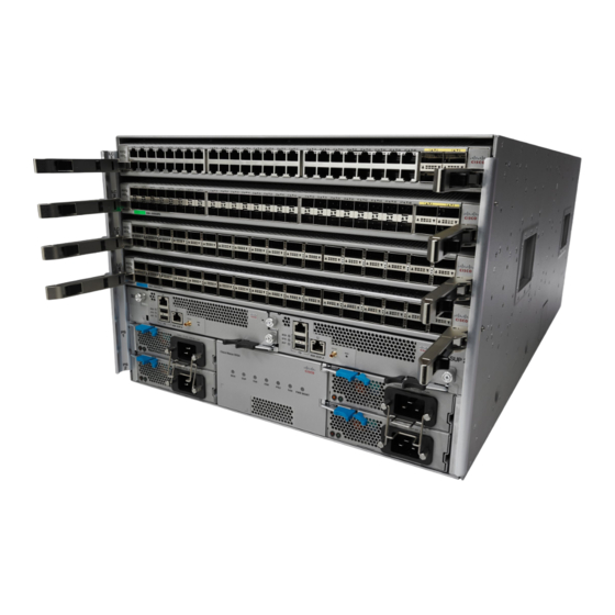
- Page 14 The following figure shows the hardware features seen from the rear of the chassis (one fan tray has been removed to show the fabric modules behind the fan trays). Cisco Nexus 9504 ACI-Mode Switch Hardware Installation Guide...
- Page 15 2 fabric only for positioning the modules behind each fan chassis on the bottom tray) support rails—do not use these handles for lifting the filled chassis) System controllers (2) Cisco Nexus 9504 ACI-Mode Switch Hardware Installation Guide...
- Page 16 Overview Overview Cisco Nexus 9504 ACI-Mode Switch Hardware Installation Guide...
-
Page 17: Preparing The Site
Altitude Requirements Altitude rating is based on power supply installed; see critical components list in the system CB report for altitude rating. Cisco Nexus 9504 ACI-Mode Switch Hardware Installation Guide... -
Page 18: Dust And Particulate Requirements
The wiring is unlikely to emit radio interference if you use a twisted-pair cable with a good distribution of grounding conductors. If you exceed the recommended distances, use a high-quality twisted-pair cable with one ground conductor for each data signal when applicable. Cisco Nexus 9504 ACI-Mode Switch Hardware Installation Guide... -
Page 19: Shock And Vibration Requirements
To plan for the power requirements of a switch, you must determine each of the following: • Power requirements for all the switch components • Minimum number of power supplies required to power the components that are installed in the switch. Cisco Nexus 9504 ACI-Mode Switch Hardware Installation Guide... - Page 20 36-port 40-Gigabit line cards (4 x 211 W = 844 W), six fabric modules (6 x 131 W = 786 W), and three fan trays (3 x 150 W = 450 W). The total is 2290 W. Cisco Nexus 9504 ACI-Mode Switch Hardware Installation Guide...
- Page 21 (16.5 A)/ (80% or 0.80) = 20.6 amps Step 4 Select one of the following power modes to determine the number of additional power supplies required for reserve power: Cisco Nexus 9504 ACI-Mode Switch Hardware Installation Guide...
- Page 22 Add at least 1 more power supply to the number of power supplies determined in step 2. N9K-PUV-3000W-B Guidelines: N9K-PUV2-3000W-B Recommended if the number of power supplies from step 2 is 1 or higher. Cisco Nexus 9504 ACI-Mode Switch Hardware Installation Guide...
- Page 23 3-kW DC power supplies You provide four 6-gauge wires (recommended) and cuts that wire to the required length. We provide four 6-gauge lugs to connect those wires to the DC power supply. Cisco Nexus 9504 ACI-Mode Switch Hardware Installation Guide...
-
Page 24: Rack And Cabinet Requirements
• Power cords for the 3-kW Universal AC power supplies are 14 feet (4.27 m) long. Note The power cables for the 3-kW DC power supply are provided by and sized you. Cisco Nexus 9504 ACI-Mode Switch Hardware Installation Guide... -
Page 25: Clearance Requirements
Vertical rack-mount posts Minimum clearance and rails required for module handles (up to 6 inches [15.24 cm] recommended for optimal airflow) when using cabinet doors Cisco Nexus 9504 ACI-Mode Switch Hardware Installation Guide... - Page 26 Side clearance, that is required for older line card handle rotation (not required for the current line cards which have handles that rotate differently). No right-side clearance required (no airflow on the right side). Cisco Nexus 9504 ACI-Mode Switch Hardware Installation Guide...
-
Page 27: Installing A Chassis
(ESD) wrist strap. This action prevents discharge damage when you handle ungrounded components during installation. Step 3 If you need access to the source power at the rack, include one of the following: Cisco Nexus 9504 ACI-Mode Switch Hardware Installation Guide... -
Page 28: Inspecting The New Switch
• Fabric modules—See the Overview in Chapter 1 for quantity and type. The switch must have only one type of fabric module that supports the installed line cards. The fabric modules must be installed in specific slots as follows (installing fabric modules in other slots can cause a module mismatch condition): Cisco Nexus 9504 ACI-Mode Switch Hardware Installation Guide... -
Page 29: Installing The Bottom-Support Rails
• 3.15-kW Dual Input Universal AC/DC power supply (N9K-PUV2-3000W-B) • 3-kW DC power supply (N9K-PDC-3000W-B) • Rack Mount kit • Rack mount kit for the Cisco Nexus 9504 (N9K-C9504-RMK) chassis • Bottom-support rails (2) • M6 mounting screws (20) • 10-32 mounting screws (20) •... - Page 30 7.1 RU (12.4 in [31.6 cm]) of vertical space above the rails to install the chassis, see the following figure. You can expand the rail so that its mounting brackets are spaced between 24 to 32 inches (61.0 to 81.3 cm). Cisco Nexus 9504 ACI-Mode Switch Hardware Installation Guide...
- Page 31 3/4 inch screws for each end of the rail (using a total of 6 screws for the rail as shown in the following figure) and tighten each screw to 40 in-lbs (4.5 N.m) of torque. Adjustable bottom-support M6 x 19-mm (or 12-24 x 3/4 rails (2) in.) Phillips screws (at least 6 per rail) Cisco Nexus 9504 ACI-Mode Switch Hardware Installation Guide...
-
Page 32: Installing A Chassis In A Rack Or Cabinet
Part of this kit has already been used to install the bottom-support rails. You have at least 12 12-24 x 3/4-inch or M6 x 19 mm Phillips screws, which are required for attaching the chassis to the rack. Cisco Nexus 9504 ACI-Mode Switch Hardware Installation Guide... - Page 33 (such as power supplies, fans, or cards); these types of handles are not designed to support the weight of the unit. Step 3 Use the mechanical lift to move and align the rear of the chassis to the front of the four-post rack or cabinet. Cisco Nexus 9504 ACI-Mode Switch Hardware Installation Guide...
- Page 34 Push the sides of the lower half of the front side of Rack vertical mounting rails on the rack. the chassis (do not push or lift any modules or module handles). Cisco Nexus 9504 ACI-Mode Switch Hardware Installation Guide...
-
Page 35: Grounding The Chassis
You can also ground the chassis, which is required if the rack is not grounded, by attaching a customer-supplied grounding cable. Attach the cable to the chassis grounding pad and the facility ground. Cisco Nexus 9504 ACI-Mode Switch Hardware Installation Guide... - Page 36 Secure the grounding lug to the chassis grounding pad with one M4 screw, see the previous figure. Tighten the screw to 11 to 15 in-lb (1.24 to 1.69 N·m) of torque. Step 4 Prepare the other end of the grounding wire and connect it to the facility ground. Cisco Nexus 9504 ACI-Mode Switch Hardware Installation Guide...
-
Page 37: Starting Up The Switch
You turn on the switch when you connect its power supplies to one or two power sources. Warning Statement 1004 Installation Instructions Read the installation instructions before using, installing or connecting the system to the power source. Cisco Nexus 9504 ACI-Mode Switch Hardware Installation Guide... -
Page 38: Connecting A 3-Kw Ac Power Supply To An Ac Power Source
The 3-kW Universal AC/DC power supply can be connected to a 240-to-380-V DC circuit equipped with positive, negative, and ground terminals. This procedure is for connecting the power supply to a DC power source. Cisco Nexus 9504 ACI-Mode Switch Hardware Installation Guide... -
Page 39: Connecting A 3-Kw Dc Power Supply To A Dc Power Source
• Four power cables (6-AWG cables recommended). Note Use colored cables to designate positive and negative polarity. You need two cables that are colored for positive polarity and two cables that are colored for negative polarity. Cisco Nexus 9504 ACI-Mode Switch Hardware Installation Guide... - Page 40 Use a torque screwdriver to unscrew the three screws that are on the cover of the terminal box. the cover is located on the front of the power supply and lifts off the cover as shown in the following figure. Cisco Nexus 9504 ACI-Mode Switch Hardware Installation Guide...
- Page 41 Turn the power switch on the power supply to ON (labeled 1 on the power supply). The LEDs flash and then the OK LED turns on (green) in addition to the Input LEDs. What to do next You are ready to connect the switch to the network. Cisco Nexus 9504 ACI-Mode Switch Hardware Installation Guide...
- Page 42 Installing a Chassis Connecting a 3-kW DC Power Supply to a DC Power Source Cisco Nexus 9504 ACI-Mode Switch Hardware Installation Guide...
-
Page 43: Connecting The Switch To The Aci Fabric
As shown in the following figure, each APIC is connected to one or two leaf switches and each leaf switch should be connected to every spine switch in the same fabric. Cisco Nexus 9504 ACI-Mode Switch Hardware Installation Guide... -
Page 44: Preparing To Connect To Other Devices
Cisco equipment. In situations where long parallel cable runs cannot be separated by at least 3.3 feet (1 meter), we recommend that you shield any potential noise sources by housing them in a grounded metallic conduit. -
Page 45: Connecting Leaf Switches To Apics
Connecting Leaf Switches to APICs You must downlink one or two (recommended for redundancy) Cisco Nexus 9300 platform ACI-mode leaf switches to each Application Policy Infrastructure Controller (APIC) in your ACI fabric. The type of virtual interface card (VIC) installed on the APIC determines the types of interface cables that you can use to connect the leaf switches to the APICs. - Page 46 Connect the other end of the interface cable to a downlink port on a leaf switch. • For a Cisco 10GBASE-LR or -SR transceiver and cable, insert the transceiver into a downlink optical port on a leaf switch before connecting the cable to the transceiver.
-
Page 47: Connecting Leaf Switches To Spine Switches
You cannot include NX-OS line cards in the same chassis when running in ACI mode. Note Multiple uplinks from a leaf switch to a spine switch is supported. A symmetrical topology is recommended so that all devices have equal access to resources. Cisco Nexus 9504 ACI-Mode Switch Hardware Installation Guide... -
Page 48: Installing A Gigabit Ethernet Module (Gem)
Migration of Nodes From a First Generation Switch to a Second Generation Switch You have first generation Cisco Nexus 9000 series switches that may or may not be comprising a virtual port channel (vPC). You are migrating to second generation Cisco Nexus 9000 series switches using the same cables. - Page 49 Before you begin • Move any Cisco Application Policy Infrastructure Controllers (APICs) that are connected to the first generation switches that you are migrating to any other switches in the fabric and wait for the Cisco APIC cluster to become "Fully Fit."...
-
Page 50: Setting Up An Optional Console Interface
Register the new second generation switch with the Cisco APIC. Register the new node with the same node name and node ID. This switch becomes part of the fabric. The Cisco APIC pushes the policies to the new switch and keeps down the vPC legs because there is a mismatch of the generation of switches. -
Page 51: Setting Up An Optional Management Connection
DB-9 connector on the other end of the cable to the serial port on the console device. What to do next You can now perform the initial configuration for the switch (see the Cisco ACI Getting Started Guide). Setting Up an Optional Management Connection You can optionally set up an out-of-band management connection for monitoring and troubleshooting purposes. - Page 52 Use the narrow end of the optics extraction tool to carefully remove the transceiver module (see the following image). Step 4 Place the transceiver module in an antistatic bag or other protective environment. Cisco Nexus 9504 ACI-Mode Switch Hardware Installation Guide...
-
Page 53: Maintaining Transceivers And Optical Cables
• Inspect routinely for dust and damage. If you suspect damage, clean and then inspect fiber ends under a microscope to determine if damage has occurred. Cisco Nexus 9504 ACI-Mode Switch Hardware Installation Guide... - Page 54 Connecting the Switch to the ACI Fabric Maintaining Transceivers and Optical Cables Cisco Nexus 9504 ACI-Mode Switch Hardware Installation Guide...
-
Page 55: Replacing Or Installing Modules, Fan Trays, And Power Supplies
When you remove the active supervisor, the switch automatically makes the other supervisor active. But, all modules in the switch are reset because the switchover is stateless. If the switch has two installed supervisor Cisco Nexus 9504 ACI-Mode Switch Hardware Installation Guide... - Page 56 If you are replacing a module that is currently in the chassis, remove the existing module from the chassis by following these steps: a) Disconnect and label the following cables from the module: • Console cable Cisco Nexus 9504 ACI-Mode Switch Hardware Installation Guide...
- Page 57 Align the back of the module to the guides in the open supervisor slot and slide the module all the way into the slot. See the following figure. The module stops when its front is about 0.25 inches (0.6 cm) outside the front of the chassis. Cisco Nexus 9504 ACI-Mode Switch Hardware Installation Guide...
- Page 58 Screw in the two captive screws to secure the module to the chassis. Tighten the screws to 8 in-lb (0.9 N·m) of torque. f) Attach the following cables to the module: Cisco Nexus 9504 ACI-Mode Switch Hardware Installation Guide...
-
Page 59: Upgrading A Supervisor Module
Warning Statement 1034 Backplane Voltage Hazardous voltage or energy is present on the backplane when the system is operating. Use caution when servicing. Cisco Nexus 9504 ACI-Mode Switch Hardware Installation Guide... - Page 60 Set it on an antistatic surface or inside an antistatic bag. Step 4 To install the new module, follow these steps: a) Slide and hold the middle handle on the ejector lever toward the end of the lever. See the following figure. Cisco Nexus 9504 ACI-Mode Switch Hardware Installation Guide...
- Page 61 The module is fully seated on the midplane. e) Screw in the two captive screws to secure the module to the chassis. Tighten each of these screws to 8 in-lb (0.9 N·m) of torque. Cisco Nexus 9504 ACI-Mode Switch Hardware Installation Guide...
-
Page 62: Installing Or Replacing A Line Card
Disconnect and label each of the interface cables from the module. b) Push and hold the release button on both ejector levers and then rotate both levers 45 degrees from the module as shown in the following figure. Cisco Nexus 9504 ACI-Mode Switch Hardware Installation Guide... - Page 63 To install the new line card, follow these steps: a) Press and hold the release button on both ejector levers. Rotate the end of each lever away from the chassis as shown in the following figure. Cisco Nexus 9504 ACI-Mode Switch Hardware Installation Guide...
- Page 64 Verify that the line card LEDs turn on and appear as follows: • The Status (STS or STA) LED turns on and becomes green. • For each connected port, the port LED turns on and becomes green or amber. Cisco Nexus 9504 ACI-Mode Switch Hardware Installation Guide...
-
Page 65: Installing And Removing A Blank Line Card
Note The latches are stiff and may require extra force to fully engage with the brackets on the sides of the chassis. Cisco Nexus 9504 ACI-Mode Switch Hardware Installation Guide... - Page 66 The latches are stiff and may require extra force to fully disengage with the brackets on the sides of the chassis. b) Hold the blank line card using both the hands and pull the blank line card completely out of the chassis slot. Cisco Nexus 9504 ACI-Mode Switch Hardware Installation Guide...
-
Page 67: Replacing A Fan Tray
If the module is damaged, contact the Technical Assistance Center (TAC) and wait until you have an undamaged fan tray to install. Step 2 Unscrew the two captive screws on the front of the fan tray until each screw is free of the chassis. See the following figure. Cisco Nexus 9504 ACI-Mode Switch Hardware Installation Guide... -
Page 68: Installing A Fan Tray
• If you are replacing a fabric module behind the open fan tray slot, that replacement operation is completed. Step 1 Use both of your hands to hold the two handles on the front of the fan tray that you are installing. Cisco Nexus 9504 ACI-Mode Switch Hardware Installation Guide... -
Page 69: Replacing A Fabric Module
The switch uses three to six fabric modules depending on the requirements of the line cards that are installed in the chassis. Note Do not mix fabric module types in the same switch. Cisco Nexus 9504 ACI-Mode Switch Hardware Installation Guide... -
Page 70: Removing A Fabric Module
Remove the fan tray that covers the fabric module by following these steps: a) Unscrew the two captive screws on the front of the fan tray until each screw is free of the chassis. See Callout 1 in the following figure. Cisco Nexus 9504 ACI-Mode Switch Hardware Installation Guide... - Page 71 Remove the fabric module that you are replacing by following these steps: a) Unscrew the screw on the center of each of the two handles on the fabric module. See Callout 1 in the following figure. Cisco Nexus 9504 ACI-Mode Switch Hardware Installation Guide...
- Page 72 Pull on both handles to remove the fabric module Screw in the 2 captive screws (1 on each handle) to from the chassis. the module. Tighten each of these screws to 8 in-lb (0.9 N·m) of torque. Cisco Nexus 9504 ACI-Mode Switch Hardware Installation Guide...
-
Page 73: Installing A Fabric Module
Callouts 1 and 2 in the following figure. Be sure that the locking posts on the top and bottom of the chassis rotate into the module so that the module can slide fully into the slot. See Callout 3 of the following figure. Cisco Nexus 9504 ACI-Mode Switch Hardware Installation Guide... - Page 74 Reinstall the fan module over the replaced fabric module by following these steps: a) Use both of your hands to hold the two handles on the front of the fan tray that you are installing. Cisco Nexus 9504 ACI-Mode Switch Hardware Installation Guide...
-
Page 75: Installing Or Replacing Power Supplies
The number of 3-kW and 3.15-kW power supplies that you install depends on the power requirements of the switch. It also depends on the power mode that you are using. To determine the power requirements of the switch, see the Power Requirements for Switch Modules section. Cisco Nexus 9504 ACI-Mode Switch Hardware Installation Guide... -
Page 76: Installing Or Replacing A 3-Kw Ac Power Supply
Do not operate the system unless all cards, faceplates, front covers, and rear covers are in place. You can install or replace any of the following Cisco Nexus 9500 Series power supplies in this switch: • 3-kW AC Power Supply •... - Page 77 Slide the handle on the middle of the power supply ejector handle about 0.25 inches (0.6 cm) and rotate the lever away from the front of the power supply. Do this while pushing the power supply all the way into the chassis. See the following figure. Cisco Nexus 9504 ACI-Mode Switch Hardware Installation Guide...
- Page 78 0.25 inches (0.6 cm) in front of the chassis. f) Rotate the ejector lever toward the front of the power supply and be sure that the other end of the lever locks into the chassis. Cisco Nexus 9504 ACI-Mode Switch Hardware Installation Guide...
-
Page 79: Installing Or Replacing A 3-Kw Universal Ac/Dc Power Supply
If the FAULT LED is on and the color is amber, that indicates that the power source connection has Note been broken. 4. Remove the power cable plug from the power supply receptacle. Cisco Nexus 9504 ACI-Mode Switch Hardware Installation Guide... - Page 80 Slide the handle on the middle of the power supply release lever toward the end of the module and rotate the lever away from the front of the power supply while pushing the power supply all the way into the chassis. See the following figure. Cisco Nexus 9504 ACI-Mode Switch Hardware Installation Guide...
- Page 81 • If you are using the combined power mode or the n+1 redundancy mode, you can connect the power cable to the same power source as used by the other power supplies in the same switch. Cisco Nexus 9504 ACI-Mode Switch Hardware Installation Guide...
-
Page 82: Installing Or Replacing A 3.15-Kw Dual Input Universal Ac/Dc Power Supply
3.15KW with either one or two input power lines operating. The HVAC/HVDC power supply provides n+n or n+x line redundancy mode in a single power supply for the Cisco Nexus 9500 Series switches. The HVAC/HVDC power supply accepts 200–240VAC or 240/380VDC input power. - Page 83 Verify that the OUT LED turns on and becomes green. Note If you use both inputs, the IN LED is green. If you use only one input, the IN LED is blinking green. Cisco Nexus 9504 ACI-Mode Switch Hardware Installation Guide...
-
Page 84: Installing Or Replacing A 3-Kw Dc Power Supply
The terminal box has four slots for four power terminals (ordered as negative [-], positive [+], positive [+], and negative [-]). Each terminal has two nuts that you use to fasten a power cable to the terminal. Cisco Nexus 9504 ACI-Mode Switch Hardware Installation Guide... - Page 85 2. Hold the power supply flat with the release lever on the upper left front end of the module. Position and orient the other end of the module at the open power supply slot in the chassis. Cisco Nexus 9504 ACI-Mode Switch Hardware Installation Guide...
- Page 86 Fully rotate the release lever away from the front Make sure that the other end of the lever grabs the of the module. front of the chassis to push the module onto the connectors inside the slot. Cisco Nexus 9504 ACI-Mode Switch Hardware Installation Guide...
- Page 87 2. Use a torque screwdriver to unscrew three screws on the cover for the terminal box that is located on the front of the power supply. Then lift off the cover as shown in the following figure. Remove 3 screws from the Remove the cover. safety cover. Cisco Nexus 9504 ACI-Mode Switch Hardware Installation Guide...
- Page 88 2. Turn the power switch on the power supply to ON (labeled 1 on the power supply). The LEDs flashes and then the OK LED turns on (green) in addition to the Input LEDs. What to do next You are ready to connect the switch to the network. Cisco Nexus 9504 ACI-Mode Switch Hardware Installation Guide...
-
Page 89: System Specifications
Supervisor modules Without mounting Inside chassis: 20.67 1.75 inches (4.4 cm) brackets: 7.0 inches inches (52.5 cm) (17.78 cm) Ejector levers outside With mounting brackets: chassis: 0.75 inches (1.9 8.0 inches (20.32 cm) Cisco Nexus 9504 ACI-Mode Switch Hardware Installation Guide... -
Page 90: Weights For The Chassis, Modules, Fan Trays, And Power Supplies
Supervisor B module (N9K-SUP-B) 6.0 lb (2.72 kg) – Supervisor B+ module (N9K-SUP-B+) 5.3 lb (2.39 kg) System Controller Module (N9K-SC-A) 1.9 lb (0.9 kg) Line cards that the N9K-C9504-FM fabric modules support — Cisco Nexus 9504 ACI-Mode Switch Hardware Installation Guide... -
Page 91: Power Specifications
1 to the result. For n+1 redundancy, add one more power supply. For n+n redundancy, double the number of power supplies and provision for a second power source. To determine the typical consumption, add the typical power amounts for each module in the switch. Cisco Nexus 9504 ACI-Mode Switch Hardware Installation Guide... -
Page 92: Maximum Power Available To The Switch
90% or greater (20 to 100% load) Redundancy Modes Combined, n+1, and n+n RoHS Compliance Hot Swappable Airflow Direction Port-side intake airflow 3000-W Universal AC/DC Power Supply Specifications Property Specification Power 3000 W Cisco Nexus 9504 ACI-Mode Switch Hardware Installation Guide... -
Page 93: 3000-W Dual Input Universal Ac/Dc Power Supply Specifications
The following subtopics list the specifications for supported power cables. 3-kW AC Power Cable Specifications Locale Power Cord Part Number Cord Set Rating Power Cord Illustration Argentina CAB-9K16A-ARG 16 A, 250 VAC Cisco Nexus 9504 ACI-Mode Switch Hardware Installation Guide... - Page 94 South Africa CAB-9K16A-SA 16 A, 250 VAC Australia and New Zealand CAB-AC-16A-AUS 16 A, 250 VAC Peoples Republic of China CAB-AC-16A-CH 16 A, 250 VAC Continental Europe CAB-AC-2500W-EU 16 A, 250 VAC Cisco Nexus 9504 ACI-Mode Switch Hardware Installation Guide...
- Page 95 Israel CAB-AC-2500W-ISRL 16 A, 250 VAC Japan and North America CAB-AC-2500W-US1 16 A, 250 VAC (nonlocking) 200-240 VAC operation Japan and North America CAB-AC-C6K-TWLK 16 A, 250 VAC (locking) 200-240 VAC operation Cisco Nexus 9504 ACI-Mode Switch Hardware Installation Guide...
- Page 96 16 A, 250 VAC (IEC 60320 C19 to EL 218) CAB-AC-STRT-C19US 16 A, 250 VAC (straight blade NEMA 6-20 plug) All except Argentina, Brazil, NO-PWR-CORD No power cord is included with N.A. and Japan order. Cisco Nexus 9504 ACI-Mode Switch Hardware Installation Guide...
-
Page 97: 3-Kw Universal Ac/Dc And 3-Kw Dual Input Universal Ac/Dc Power Cable Specifications
3-kW Universal AC/DC and 3-kW Dual Input Universal AC/DC Power Cable Specifications Locale Power Cord Part Number Cord Set Rating Power Cord Illustration Australia and New Zealand CAB-AC-16A-SG-AZ 16 A, 250 VAC (AU20LS3/Saf-D-Grid) CAB-AC-16A-SG-EU 16A, 250 VAC Israel CAB-AC-16A-SG-IS 16 A, 250 VAC Cisco Nexus 9504 ACI-Mode Switch Hardware Installation Guide... - Page 98 System Specifications Locale Power Cord Part Number Cord Set Rating Power Cord Illustration International/UK CAB-AC-16A-SG-IN 16 A, 250 VAC Italy CAB-AC-16A-SG-IT 16 A, 250 VAC South Africa CAB-AC-16A-SG-SA 16 A, 250 VAC Cisco Nexus 9504 ACI-Mode Switch Hardware Installation Guide...
- Page 99 North America CAB-AC-20A-SG-C20 250 VAC 20 A North America CAB-AC-20A-SG-US 16 A, 250 VAC North America (non locking) CAB-AC-20A-SG-US2 250 VAC 20 A 200-240 VAC operation North America CAB-AC-20A-SG-US3 250 VAC 20 A Cisco Nexus 9504 ACI-Mode Switch Hardware Installation Guide...
- Page 100 277 VAC 20 A operation International, CAB-HV-25A-SG-IN1 400 VAC 20 A Saf-D-Grid/Saf-D-Grid International, Ring Terminal CAB-HV-25A-SG-IN2 20A, 300 VAC/500 VDC source plug, Ring Terminal/Saf-D-Grid North America CAB-HV-25A-SG-US1 277 VAC/ 240 VDC/ 380 VDC 25 A Cisco Nexus 9504 ACI-Mode Switch Hardware Installation Guide...
-
Page 101: 3-Kw Dc Power Supply Power Cord Specifications
Each 3-kW DC power supply requires four customer-supplied power cables (two negative cables and two positive cables). We recommend using six gauge cables. Cisco supplies 6-gauge lugs for connections to the power supply. You supply the connectors that are required to connect the cables to the DC power source. - Page 102 System Specifications 3-kW DC Power Supply Power Cord Specifications Cisco Nexus 9504 ACI-Mode Switch Hardware Installation Guide...
-
Page 103: Leds
Line cards (I/O modules) are all operational. Amber Check Line Card LEDs, on page 96 for more information. Power supplies are all operational. Green Amber Check the Power Supply LEDs for more information. Cisco Nexus 9504 ACI-Mode Switch Hardware Installation Guide... -
Page 104: System Controller Leds
The following table describes the possible states for each of these LEDs. Color Status Flashing blue The operator has activated this LED to identify this module in the chassis. This module is not being identified. Cisco Nexus 9504 ACI-Mode Switch Hardware Installation Guide... -
Page 105: Fan Tray Leds
The fabric modules behind this fan tray are operational. Amber At least one fabric module behind this fan tray is not operating. No power is going to the fabric module behind this fan tray. Cisco Nexus 9504 ACI-Mode Switch Hardware Installation Guide... -
Page 106: Fabric Module Leds
LED. The following table describes the possible states for each of these LEDs. Color Status Flashing blue The operator has activated this LED to identify this module in the chassis. This LED is not being used. Cisco Nexus 9504 ACI-Mode Switch Hardware Installation Guide... -
Page 107: Power Supply Leds
The power supply may not be properly installed in the chassis. Either all the installed power supplies are not receiving power or an uninstalled power supply is not receiving power. Cisco Nexus 9504 ACI-Mode Switch Hardware Installation Guide... - Page 108 Power supply is installed without a connection to a power source. (10 seconds) then amber Amber Power supply failure—possibly one of the following conditions: • Over voltage • Over current • Over temperature • Power supply fan failure Cisco Nexus 9504 ACI-Mode Switch Hardware Installation Guide...
-
Page 109: Additional Kits
• M6 x 19-mm Phillips screws (20) • Adjustable bottom-support rails (2) RJ-45 rollover cable DB-9F/RJ-45F PC terminal Ground lug kit 1 kit • Two-hole lug (1) • M4 x 8-mm Phillips pan-head screws (2) Cisco Nexus 9504 ACI-Mode Switch Hardware Installation Guide... - Page 110 1-Year Limited Warranty for Hardware Note If you do not receive a part that is listed in this document, contact Cisco Technical Support at this URL: http://www.cisco.com/warp/public/687/Directory/DirTAC.shtml. If you purchased this product through a Cisco reseller, you may receive contents in your kit, such as documentation, hardware, and power cables.
Need help?
Do you have a question about the Nexus 9504 and is the answer not in the manual?
Questions and answers