Cisco Nexus 9504 Hardware Installation Manual
Nx-os mode switch
Hide thumbs
Also See for Nexus 9504:
- Hardware installation manual (110 pages) ,
- Configuration manual (11 pages) ,
- Hardware installation manual (110 pages)
Table of Contents
Advertisement
Quick Links
Advertisement
Table of Contents

Related Manuals for Cisco Nexus 9504


Summary of Contents for Cisco Nexus 9504
- Page 1 Cisco Nexus 9504 NX-OS Mode Switch Hardware Installation Guide First Published: 2014-03-24 Last Modified: 2021-02-16 Americas Headquarters Cisco Systems, Inc. 170 West Tasman Drive San Jose, CA 95134-1706 http://www.cisco.com Tel: 408 526-4000 800 553-NETS (6387) Fax: 408 527-0883...
- Page 2 Any products and features described herein as in development or available at a future date remain in varying stages of development and will be offered on a when-and if-available basis. Any such product or feature roadmaps are subject to change at the sole discretion of Cisco and Cisco will have no liability for delay in the delivery or failure to deliver any products or feature roadmap items that may be set forth in this document.
-
Page 3: Table Of Contents
Shock and Vibration Requirements Grounding Requirements Planning for Power Requirements Rack and Cabinet Requirements Clearance Requirements C H A P T E R 3 Installing a Chassis Installing a Rack or Cabinet Cisco Nexus 9504 NX-OS Mode Switch Hardware Installation Guide... - Page 4 Displaying Environmental Information for the Switch Displaying the Current State of a Module Displaying Temperatures for a Module Connecting to a Module Saving the Module Configuration Shutting Down or Starting Up a Module Cisco Nexus 9504 NX-OS Mode Switch Hardware Installation Guide...
- Page 5 Migrating the Switch from Using 40-Gigabit Line Cards to Using 100-Gigabit -EX/-FX Line Cards A P P E N D I X A System Specifications Environmental Specifications Switch Dimensions Weights and Quantities for the Chassis, Modules, Fan Trays, and Power Supplies Cisco Nexus 9504 NX-OS Mode Switch Hardware Installation Guide...
- Page 6 System Controller LEDs Supervisor Module LEDs Fan Tray LEDs Fabric Module LEDs Line Card LEDs Power Supply LEDs A P P E N D I X C Additional Kits Accessory Kit Cisco Nexus 9504 NX-OS Mode Switch Hardware Installation Guide...
-
Page 7: Preface
Audience, on page vii • Documentation Conventions, on page vii • Related Documentation for Cisco Nexus 9000 Series NX-OS Software, on page viii • Documentation Feedback, on page x • Obtaining Documentation and Submitting a Service Request , on page x... -
Page 8: Related Documentation For Cisco Nexus 9000 Series Nx-Os Software
These guides are available at the following URL: https://www.cisco.com/en/US/products/ps13386/products_installation_and_configuration_guides_list.html The documents in this category include: • Cisco Nexus 2000 Series NX-OS Fabric Extender Software Configuration Guide for Cisco Nexus 9000 Series Switches • Cisco Nexus 9000 Series NX-OS Fundamentals Configuration Guide •... - Page 9 • Cisco Nexus 9000 Series NX-OS VXLAN Configuration Guide Other Software Documents • Cisco Nexus 7000 Series and 9000 Series NX-OS MIB Quick Reference • Cisco Nexus 9000 Series NX-OS Programmability Guide • Cisco Nexus 9000 Series NX-OS Software Upgrade and Downgrade Guide •...
-
Page 10: Documentation Feedback
What's New in Cisco Product Documentation, at: https://www.cisco.com/warp/public/687/Directory/DirTAC.shtml. Subscribe to What's New in Cisco Product Documentation, which lists all new and revised Cisco technical documentation as an RSS feed and delivers content directly to your desktop using a reader application. The RSS feeds are a free service. -
Page 11: Overview
• Fabric modules in slots FM 1 to FM 6 (numbered from left to right on the chassis) See the following table for the required fabric module types and quantities required for maximum bandwidth. Cisco Nexus 9504 NX-OS Mode Switch Hardware Installation Guide... - Page 12 N9K-C9504-FM-E N9K-X9732C-EX N9K-X9732C-FX N9K-X9736C-EX N9K-X9736C-FX N9K-X9736Q-FX N9K-X9788TC-FX N9K-C9504-FM-S N9K-X9432C-S N9K-C9504-FM-R N9K-X9636C-RX N9K-X9636C-R N9K-X9636Q-R N9K-X96136YC-R N9K-C9504-FM-G N9K-X97160YC-EX N9K-X9736C-FX N9K-X9788TC-FX N9K-X9716D-GX Note that -G fabric modules require the N9K-C9504-FAN2 fan trays for operation. Cisco Nexus 9504 NX-OS Mode Switch Hardware Installation Guide...
- Page 13 • Cisco Nexus 9500 Series 3-kW AC power supply (N9K-PAC-3000W-B) • Cisco Nexus 9500 Series 3-kW Universal AC/DC power supply (N9K-PUV-3000W-B) • Cisco Nexus 9500 Series 3.15-kW Dual Input Universal AC/DC power supply (N9K-PUV2-3000W-B) • Cisco Nexus 9500 Series 3-kW (-48 V) DC power supply (N9K-PDC-3000W-B)
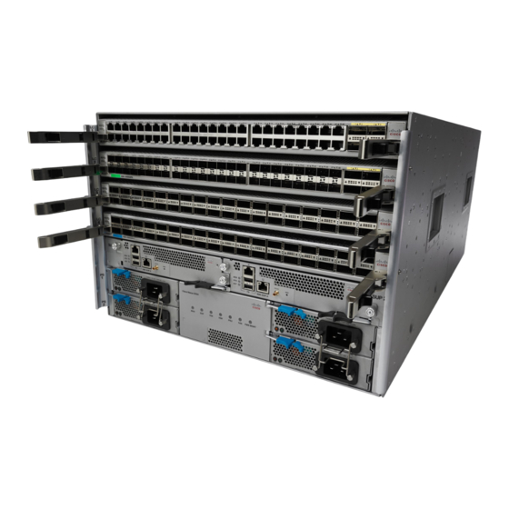
- Page 14 The following figure shows the hardware features seen from the rear of the chassis (one fan tray has been removed to show the fabric modules behind the fan trays). Cisco Nexus 9504 NX-OS Mode Switch Hardware Installation Guide...
- Page 15 2 fabric only for positioning the modules behind each fan chassis on the bottom tray) support rails—do not use these handles for lifting the filled chassis) System controllers (2) Cisco Nexus 9504 NX-OS Mode Switch Hardware Installation Guide...
- Page 16 Overview Overview Cisco Nexus 9504 NX-OS Mode Switch Hardware Installation Guide...
-
Page 17: Preparing The Site
Altitude Requirements Altitude rating is based on power supply installed; see critical components list in the system CB report for altitude rating. Cisco Nexus 9504 NX-OS Mode Switch Hardware Installation Guide... -
Page 18: Dust And Particulate Requirements
The wiring is unlikely to emit radio interference if you use a twisted-pair cable with a good distribution of grounding conductors. If you exceed the recommended distances, use a high-quality twisted-pair cable with one ground conductor for each data signal when applicable. Cisco Nexus 9504 NX-OS Mode Switch Hardware Installation Guide... -
Page 19: Shock And Vibration Requirements
To plan for the power requirements of a switch, you must determine each of the following: • Power requirements for all the switch components • Minimum number of power supplies required to power the components that are installed in the switch. Cisco Nexus 9504 NX-OS Mode Switch Hardware Installation Guide... - Page 20 540 W Line cards that are supported by N9K-C9504-FM-E and N9K-C9504-FM-E2 fabric modules 234 W – 48-port 1/10/25-Gigabit Ethernet SFP28 and 4-port 40/100-Gigabit Ethernet QSFP28 line 415 W 516 W card (N9K-X97160YC-EX) Cisco Nexus 9504 NX-OS Mode Switch Hardware Installation Guide...
- Page 21 (see Step 1) by the output wattage (3000 W) of the power supplies installed in the switch. Round up the fractional result to the nearest ones digit. Cisco Nexus 9504 NX-OS Mode Switch Hardware Installation Guide...
- Page 22 (16.5 A)/ (80% or 0.80) = 20.6 amps Step 4 Select one of the following power modes to determine the number of additional power supplies required for reserve power: Cisco Nexus 9504 NX-OS Mode Switch Hardware Installation Guide...
- Page 23 Add at least 1 more power supply to the number of power supplies determined in step 2. N9K-PUV-3000W-B Guidelines: N9K-PUV2-3000W-B Recommended if the number of power supplies from step 2 is 1 or higher. Cisco Nexus 9504 NX-OS Mode Switch Hardware Installation Guide...
- Page 24 3-kW DC power supplies You provide four 6-gauge wires (recommended) and cuts that wire to the required length. We provide four 6-gauge lugs to connect those wires to the DC power supply. Cisco Nexus 9504 NX-OS Mode Switch Hardware Installation Guide...
-
Page 25: Rack And Cabinet Requirements
• Power cords for the 3-kW Universal AC power supplies are 14 feet (4.27 m) long. Note The power cables for the 3-kW DC power supply are provided by and sized you. Cisco Nexus 9504 NX-OS Mode Switch Hardware Installation Guide... -
Page 26: Clearance Requirements
Vertical rack-mount posts Minimum clearance and rails required for module handles (up to 6 inches [15.24 cm] recommended for optimal airflow) when using cabinet doors Cisco Nexus 9504 NX-OS Mode Switch Hardware Installation Guide... - Page 27 Side clearance, that is required for older line card handle rotation (not required for the current line cards which have handles that rotate differently). No right-side clearance required (no airflow on the right side). Cisco Nexus 9504 NX-OS Mode Switch Hardware Installation Guide...
- Page 28 Preparing the Site Clearance Requirements Cisco Nexus 9504 NX-OS Mode Switch Hardware Installation Guide...
-
Page 29: Installing A Chassis
(ESD) wrist strap. This action prevents discharge damage when you handle ungrounded components during installation. Step 3 If you need access to the source power at the rack, include one of the following: Cisco Nexus 9504 NX-OS Mode Switch Hardware Installation Guide... -
Page 30: Inspecting The New Switch
The fabric modules must be installed in specific slots as follows (installing fabric modules in other slots can cause a module mismatch condition): Cisco Nexus 9504 NX-OS Mode Switch Hardware Installation Guide... -
Page 31: Installing The Bottom-Support Rails
• 3.15-kW Dual Input Universal AC/DC power supply (N9K-PUV2-3000W-B) • 3-kW DC power supply (N9K-PDC-3000W-B) • Rack Mount kit • Rack mount kit for the Cisco Nexus 9504 (N9K-C9504-RMK) chassis • Bottom-support rails (2) • M6 mounting screws (20) • 10-32 mounting screws (20) •... - Page 32 7.1 RU (12.4 in [31.6 cm]) of vertical space above the rails to install the chassis, see the following figure. You can expand the rail so that its mounting brackets are spaced between 24 to 32 inches (61.0 to 81.3 cm). Cisco Nexus 9504 NX-OS Mode Switch Hardware Installation Guide...
- Page 33 3/4 inch screws for each end of the rail (using a total of 6 screws for the rail as shown in the following figure) and tighten each screw to 40 in-lbs (4.5 N.m) of torque. Adjustable bottom-support M6 x 19-mm (or 12-24 x 3/4 rails (2) in.) Phillips screws (at least 6 per rail) Cisco Nexus 9504 NX-OS Mode Switch Hardware Installation Guide...
-
Page 34: Installing A Chassis In A Rack Or Cabinet
Part of this kit has already been used to install the bottom-support rails. You have at least 12 12-24 x 3/4-inch or M6 x 19 mm Phillips screws, which are required for attaching the chassis to the rack. Cisco Nexus 9504 NX-OS Mode Switch Hardware Installation Guide... - Page 35 (such as power supplies, fans, or cards); these types of handles are not designed to support the weight of the unit. Step 3 Use the mechanical lift to move and align the rear of the chassis to the front of the four-post rack or cabinet. Cisco Nexus 9504 NX-OS Mode Switch Hardware Installation Guide...
- Page 36 Push the sides of the lower half of the front side of Rack vertical mounting rails on the rack. the chassis (do not push or lift any modules or module handles). Cisco Nexus 9504 NX-OS Mode Switch Hardware Installation Guide...
-
Page 37: Grounding The Chassis
You can also ground the chassis, which is required if the rack is not grounded, by attaching a customer-supplied grounding cable. Attach the cable to the chassis grounding pad and the facility ground. Cisco Nexus 9504 NX-OS Mode Switch Hardware Installation Guide... - Page 38 Secure the grounding lug to the chassis grounding pad with one M4 screw, see the previous figure. Tighten the screw to 11 to 15 in-lb (1.24 to 1.69 N·m) of torque. Step 4 Prepare the other end of the grounding wire and connect it to the facility ground. Cisco Nexus 9504 NX-OS Mode Switch Hardware Installation Guide...
-
Page 39: Starting Up The Switch
You turn on the switch when you connect its power supplies to one or two power sources. Warning Statement 1004 Installation Instructions Read the installation instructions before using, installing or connecting the system to the power source. Cisco Nexus 9504 NX-OS Mode Switch Hardware Installation Guide... -
Page 40: Connecting A 3-Kw Ac Power Supply To An Ac Power Source
The 3-kW Universal AC/DC power supply can be connected to a 240-to-380-V DC circuit equipped with positive, negative, and ground terminals. This procedure is for connecting the power supply to a DC power source. Cisco Nexus 9504 NX-OS Mode Switch Hardware Installation Guide... -
Page 41: Connecting A 3-Kw Dc Power Supply To A Dc Power Source
• Four power cables (6-AWG cables recommended). Note Use colored cables to designate positive and negative polarity. You need two cables that are colored for positive polarity and two cables that are colored for negative polarity. Cisco Nexus 9504 NX-OS Mode Switch Hardware Installation Guide... - Page 42 Use a torque screwdriver to unscrew the three screws that are on the cover of the terminal box. the cover is located on the front of the power supply and lifts off the cover as shown in the following figure. Cisco Nexus 9504 NX-OS Mode Switch Hardware Installation Guide...
- Page 43 The LEDs flash and then the OK LED turns on (green) in addition to the Input LEDs. What to do next You are ready to connect the switch to the network. Cisco Nexus 9504 NX-OS Mode Switch Hardware Installation Guide...
- Page 44 Installing a Chassis Connecting a 3-kW DC Power Supply to a DC Power Source Cisco Nexus 9504 NX-OS Mode Switch Hardware Installation Guide...
-
Page 45: Connecting The Switch To The Network
• Do not touch the ends of connectors. Touching the ends can leave fingerprints and cause other contamination. Cisco Nexus 9504 NX-OS Mode Switch Hardware Installation Guide... -
Page 46: Connecting A Console To The Switch
You make this local management connection between the asynchronous serial port on a supervisor module and a console device capable of asynchronous transmission. Typically, you can use a computer terminal as the console device. On the supervisor modules, you use the console serial port. Cisco Nexus 9504 NX-OS Mode Switch Hardware Installation Guide... -
Page 47: Connecting The Management Interface
The supervisor management port (MGMT ETH) provides out-of-band management, which enables you to use the command-line interface (CLI) to manage the switch by its IP address. This port uses a 10/100/1000 Ethernet connection with an RJ-45 interface. Cisco Nexus 9504 NX-OS Mode Switch Hardware Installation Guide... -
Page 48: Creating The Initial Switch Configuration
To connect the switch to the network, you can use the default choices for each configuration except the IP address, which you must provide. You can perform the other configurations later as described in the Cisco Nexus 9000 Series NX-OS Fundamentals Configuration Guide. - Page 49 Enter the IP address for the management interface. The software asks for the Mgmt0 IPv4 netmask. Step 6 Enter a network mask for the management interface. The software asks if you need to edit the configuration. Cisco Nexus 9504 NX-OS Mode Switch Hardware Installation Guide...
-
Page 50: Connecting Interface Ports
You can disconnect a BASE-T (copper) port from the network by removing a copper network interface cable with RJ-45 connectors from the line card interface port. Before you begin Follow the ESD-preventative protocol, such as wearing a grounded ESD wrist strap, whenever handling electronic components. Cisco Nexus 9504 NX-OS Mode Switch Hardware Installation Guide... -
Page 51: Connecting An Optical Port To The Network
If using an optical cable, insert the optical cable into the installed transceiver. Disconnecting Optical Ports from the Network When removing fiber-optic transceivers, you must remove the fiber-optic cables from a transceiver before removing the transceiver from the port. Cisco Nexus 9504 NX-OS Mode Switch Hardware Installation Guide... -
Page 52: Optic Transceiver Removal Using The Optics Extraction Tool
Remove the fiber-optic cables from the transceiver module before removing the transceiver module. Step 2 Use the wide side of the optics extraction tool to release the bale latch (see the following image). Cisco Nexus 9504 NX-OS Mode Switch Hardware Installation Guide... -
Page 53: Maintaining Transceivers And Optical Cables
• Inspect routinely for dust and damage. If you suspect damage, clean and then inspect fiber ends under a microscope to determine if damage has occurred. Note If cable length is more than 5 meters, Auto Negotiation is not supported. Cisco Nexus 9504 NX-OS Mode Switch Hardware Installation Guide... - Page 54 Connecting the Switch to the Network Maintaining Transceivers and Optical Cables Note The N9K-X9436PQ, N9K-X9564PX, and N9K-X9564TX line cards do not support Link Training. Cisco Nexus 9504 NX-OS Mode Switch Hardware Installation Guide...
-
Page 55: Managing The Switch
Some parts of this software are covered under the GNU Public License. A copy of the license is available at http://www.gnu.org/licenses/gpl.html. Software Cisco Nexus 9504 NX-OS Mode Switch Hardware Installation Guide... - Page 56 Model number is N9K-C9504-FM-R H/W version is 0.1010 Part Number is 73-15287-01 Part Revision is 1 Manufacture Date is Year 17 Week 19 Serial number is SAL17194HVX CLEI code is 12345678 Cisco Nexus 9504 NX-OS Mode Switch Hardware Installation Guide...
- Page 57 Manufacture Date is Year 17 Week 22 Serial number is SAL17225YFS CLEI code is Module30 Module type is : System Controller 0 submodules are present Model number is N9K-SC-A H/W version is 0.2010 Cisco Nexus 9504 NX-OS Mode Switch Hardware Installation Guide...
- Page 58 CLEI code is 12345678 Fan3 ok Model number is N9K-C9504-FAN H/W version is 0.5010 Part Number is 73-15288-05 Part Revision is 2 Manufacture Date is Year 17 Week 14 Serial number is SAL171421SY Cisco Nexus 9504 NX-OS Mode Switch Hardware Installation Guide...
-
Page 59: Displaying The Hardware Inventory For A Switch
Displaying Fabric Utilization Information You can display information about hardware capacity in the module by using the show hardware capacity command. This information includes total fabric bandwidth, utilization ingress and egress, module type, Cisco Nexus 9504 NX-OS Mode Switch Hardware Installation Guide... - Page 60 36p 100G Ethernet Module N9K-X9636C-RX Fabric Module N9K-C9504-FM-R Fabric Module N9K-C9504-FM-R Fabric Module N9K-C9504-FM-R Fabric Module N9K-C9504-FM-R Fabric Module N9K-C9504-FM-R Fabric Module N9K-C9504-FM-R Supervisor Module N9K-SUP-B active * Supervisor Module N9K-SUP-B Cisco Nexus 9504 NX-OS Mode Switch Hardware Installation Guide...
- Page 61 08-96-ad-9a-e3-d8 to 08-96-ad-9a-e3-e9 FOC2107587T 18-80-90-94-43-fa to 18-80-90-94-44-0b FOC2132545C FOC21453MCY FOC21417HDX Online Diag Status ------------------ Pass Pass Pass Pass Pass Pass Pass Pass Pass Pass Pass Pass Pass Pass * this terminal session switch# Cisco Nexus 9504 NX-OS Mode Switch Hardware Installation Guide...
-
Page 62: Displaying The Backplane And Serial Number Information
00 00 00 00 00 00 00 00 00 00 00 00 00 00 00 00 00 00 00 00 00 00 00 00 00 00 00 00 00 00 00 00 Cisco Nexus 9504 NX-OS Mode Switch Hardware Installation Guide... -
Page 63: Displaying Environmental Information For The Switch
----------- -------------- N9K-PUV-3000W-B 3000 W shut N9K-PAC-3000W-B 753 W 3000 W N9K-PUV-3000W-B 3000 W shut N9K-PAC-3000W-B 760 W 3000 W Actual Power Module Model Draw Allocated Status (Watts ) (Watts ) Cisco Nexus 9504 NX-OS Mode Switch Hardware Installation Guide... -
Page 64: Displaying The Current State Of A Module
It doesn’t report on modules that are not software controlled, such as blank modules installed in empty slots to control airflow. This table provides descriptions of the module status that is displayed with the show module commands. Cisco Nexus 9504 NX-OS Mode Switch Hardware Installation Guide... - Page 65 ------------ --------------------------- powered-dn Configured Power down powered-dn Configured Power down -------------- ------ 6.1(4.11) 0.1010 6.1(4.11) 0.1010 6.1(4.11) 0.3011 6.1(4.11) 6.1(4.11) 0.2010 6.1(4.11) 0.2010 MAC-Address(es) Serial-Num -------------------------------------- ---------- 00-22-bd-f8-2a-83 to 00-22-bd-f8-2a-b6 SAL17257AHD Cisco Nexus 9504 NX-OS Mode Switch Hardware Installation Guide...
-
Page 66: Displaying Temperatures For A Module
• Sends SNMP notifications (if configured). • For sensor 2 (intake sensor), the following actions occur: • If the threshold is exceeded in a switching module, only that module is shut down. Cisco Nexus 9504 NX-OS Mode Switch Hardware Installation Guide... - Page 67 Temperature: -------------------------------------------------------------------- Module Sensor MajorThresh MinorThres CurTemp Status (Celsius) (Celsius) (Celsius) -------------------------------------------------------------------- TD2-1 TD2-2 TD2-3 VRM-1 VRM-2 VRM-3 TD2-1 TD2-2 VRM-1 VRM-2 OUTLET INLET OUTLET INLET switch# Cisco Nexus 9504 NX-OS Mode Switch Hardware Installation Guide...
-
Page 68: Connecting To A Module
To save the new configuration to nonvolatile storage, use the copy running-config startup-config command from EXEC mode. Once you enter this command, the running and the startup copies of the configuration are identical. Cisco Nexus 9504 NX-OS Mode Switch Hardware Installation Guide... -
Page 69: Shutting Down Or Starting Up A Module
Step 1 Use the configure terminal to enter the global configuration mode. Example: switch# configure terminal switch(config)# Cisco Nexus 9504 NX-OS Mode Switch Hardware Installation Guide... -
Page 70: Purging A Nonfunctioning Module From The Running Configuration
Use the show environment power command to display power usage information for the switch. The following example shows the output for a 3-kW AC power supply. switch# show environment power Power Supply: Voltage: 12 Volts Cisco Nexus 9504 NX-OS Mode Switch Hardware Installation Guide... -
Page 71: Reload A Module
You can reset a module by using the reload module slot_number command and specifying the module by its slot number in the chassis. Caution Reloading a module disrupts traffic through the module. Note To see which slots are filled with modules, use the show inventory command. Cisco Nexus 9504 NX-OS Mode Switch Hardware Installation Guide... -
Page 72: Rebooting A Switch
Step 2 Use the copy running-config startup-config command to save the running configuration. Example: switch(config)# copy running-config startup-config Step 3 Use the reload command to reload the switch. Example: switch(config)# reload Cisco Nexus 9504 NX-OS Mode Switch Hardware Installation Guide... -
Page 73: Overview Of Supervisor Modules
Supervisor B+ Supervisor B+ A Cisco Nexus 9504 chassis with -R line cards requires supervisor B or B+ modules. Supervisor modules are automatically powered up and started with the switch. To understand the terms that are used for the supervisors, see the following table. -
Page 74: Overview Of Power Modes
This mode insures load sharing, but the budget becomes half the total PSU capacity. Use a different power source for the active and reserve power sources. So that if the power source that is used for active Cisco Nexus 9504 NX-OS Mode Switch Hardware Installation Guide... - Page 75 3.0 kW each, provide enough power (6.0 kW) to meet the switch requirements (5.2 kW), so the entire switch powers up. The following table shows the results for each scenario. Cisco Nexus 9504 NX-OS Mode Switch Hardware Installation Guide...
- Page 76 The available power is 3.0 kW (output from one 3-kW power supply) and the reserve power is 3.0 kW (output from the other power supply). The available power (3.0 kW) does not meet the switch Cisco Nexus 9504 NX-OS Mode Switch Hardware Installation Guide...
- Page 77 Power Allocated (budget) for a switch is 5.2 kW and the switch has one 3-kW power supply with 220-V input and 3.0-kW output, consider the following power planning scenarios: • Scenario 1—No added power supplies Cisco Nexus 9504 NX-OS Mode Switch Hardware Installation Guide...
-
Page 78: Setting The Power Mode
Setting the Power Mode You can configure the power supply mode by using the power redundancy-mode command. Note To display the current power supply configuration, use the show environment power command. Cisco Nexus 9504 NX-OS Mode Switch Hardware Installation Guide... -
Page 79: Overview Of Fan Trays
This process can increase the noise that is made by the fan trays until you replace the missing fan tray or replace the defective fan tray. Cisco Nexus 9504 NX-OS Mode Switch Hardware Installation Guide... -
Page 80: Displaying The Status For The Fan Trays
If the status is not reported for a fan tray and the status LED is not lit for that installed fan tray, check to be sure that there is a fabric module that is installed behind the fan tray. Cisco Nexus 9504 NX-OS Mode Switch Hardware Installation Guide... -
Page 81: Replacing Or Installing Modules, Fan Trays, And Power Supplies
Verify that the grounding cable is attached to the facility earth ground. Installing or Replacing a Supervisor Module The switch can operate with one or two supervisor modules that are installed in the chassis. Cisco Nexus 9504 NX-OS Mode Switch Hardware Installation Guide... - Page 82 Supervisor A+ Supervisor B+ Supervisor B+ A Cisco Nexus 9504 chassis with -R line cards requires supervisor B or B+ modules. Warning Statement 1034 Backplane Voltage Hazardous voltage or energy is present on the backplane when the system is operating. Use caution when servicing.
- Page 83 Hold the front of the module with one hand and place your other hand under the module to support its weight. c) Align the back of the module to the guides in the open supervisor slot and slide the module all the way into the slot. See the following figure. Cisco Nexus 9504 NX-OS Mode Switch Hardware Installation Guide...
- Page 84 Make sure that the lever engages behind the front of the slot so that the module fully seats onto the connectors on the midplane. e) Screw in the two captive screws to secure the module to the chassis. Tighten the screws to 8 in-lb (0.9 N·m) of torque. Cisco Nexus 9504 NX-OS Mode Switch Hardware Installation Guide...
-
Page 85: Upgrading A Supervisor Module
Warning Statement 1034 Backplane Voltage Hazardous voltage or energy is present on the backplane when the system is operating. Use caution when servicing. Cisco Nexus 9504 NX-OS Mode Switch Hardware Installation Guide... - Page 86 Step 4 To install the new module, follow these steps: a) Slide and hold the middle handle on the ejector lever toward the end of the lever. See the following figure. Cisco Nexus 9504 NX-OS Mode Switch Hardware Installation Guide...
- Page 87 The module is fully seated on the midplane. e) Screw in the two captive screws to secure the module to the chassis. Tighten each of these screws to 8 in-lb (0.9 N·m) of torque. Cisco Nexus 9504 NX-OS Mode Switch Hardware Installation Guide...
-
Page 88: Installing Or Replacing A Line Card
Disconnect and label each of the interface cables from the module. b) Push and hold the release button on both ejector levers and then rotate both levers 45 degrees from the module as shown in the following figure. Cisco Nexus 9504 NX-OS Mode Switch Hardware Installation Guide... - Page 89 To install the new line card, follow these steps: a) Press and hold the release button on both ejector levers. Rotate the end of each lever away from the chassis as shown in the following figure. Cisco Nexus 9504 NX-OS Mode Switch Hardware Installation Guide...
- Page 90 Verify that the line card LEDs turn on and appear as follows: • The Status (STS or STA) LED turns on and becomes green. • For each connected port, the port LED turns on and becomes green or amber. Cisco Nexus 9504 NX-OS Mode Switch Hardware Installation Guide...
-
Page 91: Installing And Removing A Blank Line Card
Note The latches are stiff and may require extra force to fully engage with the brackets on the sides of the chassis. Cisco Nexus 9504 NX-OS Mode Switch Hardware Installation Guide... - Page 92 The latches are stiff and may require extra force to fully disengage with the brackets on the sides of the chassis. b) Hold the blank line card using both the hands and pull the blank line card completely out of the chassis slot. Cisco Nexus 9504 NX-OS Mode Switch Hardware Installation Guide...
-
Page 93: Replacing A Fan Tray
If the module is damaged, contact the Technical Assistance Center (TAC) and wait until you have an undamaged fan tray to install. Step 2 Unscrew the two captive screws on the front of the fan tray until each screw is free of the chassis. See the following figure. Cisco Nexus 9504 NX-OS Mode Switch Hardware Installation Guide... -
Page 94: Installing A Fan Tray
• If you are replacing a fabric module behind the open fan tray slot, that replacement operation is completed. Step 1 Use both of your hands to hold the two handles on the front of the fan tray that you are installing. Cisco Nexus 9504 NX-OS Mode Switch Hardware Installation Guide... -
Page 95: Replacing A Fabric Module
The switch uses three to six fabric modules depending on the requirements of the line cards that are installed in the chassis. Note Do not mix fabric module types in the same switch. Cisco Nexus 9504 NX-OS Mode Switch Hardware Installation Guide... -
Page 96: Removing A Fabric Module
Remove the fan tray that covers the fabric module by following these steps: a) Unscrew the two captive screws on the front of the fan tray until each screw is free of the chassis. See Callout 1 in the following figure. Cisco Nexus 9504 NX-OS Mode Switch Hardware Installation Guide... - Page 97 Remove the fabric module that you are replacing by following these steps: a) Unscrew the screw on the center of each of the two handles on the fabric module. See Callout 1 in the following figure. Cisco Nexus 9504 NX-OS Mode Switch Hardware Installation Guide...
- Page 98 Pull on both handles to remove the fabric module Screw in the 2 captive screws (1 on each handle) to from the chassis. the module. Tighten each of these screws to 8 in-lb (0.9 N·m) of torque. Cisco Nexus 9504 NX-OS Mode Switch Hardware Installation Guide...
-
Page 99: Installing A Fabric Module
Callouts 1 and 2 in the following figure. Be sure that the locking posts on the top and bottom of the chassis rotate into the module so that the module can slide fully into the slot. See Callout 3 of the following figure. Cisco Nexus 9504 NX-OS Mode Switch Hardware Installation Guide... - Page 100 Reinstall the fan module over the replaced fabric module by following these steps: a) Use both of your hands to hold the two handles on the front of the fan tray that you are installing. Cisco Nexus 9504 NX-OS Mode Switch Hardware Installation Guide...
-
Page 101: Installing Or Replacing Power Supplies
The number of 3-kW and 3.15-kW power supplies that you install depends on the power requirements of the switch. It also depends on the power mode that you are using. To determine the power requirements of the switch, see the Power Requirements for Switch Modules section. Cisco Nexus 9504 NX-OS Mode Switch Hardware Installation Guide... -
Page 102: Installing Or Replacing A 3-Kw Ac Power Supply
Do not operate the system unless all cards, faceplates, front covers, and rear covers are in place. You can install or replace any of the following Cisco Nexus 9500 Series power supplies in this switch: • 3-kW AC Power Supply •... - Page 103 Slide the handle on the middle of the power supply ejector handle about 0.25 inches (0.6 cm) and rotate the lever away from the front of the power supply. Do this while pushing the power supply all the way into the chassis. See the following figure. Cisco Nexus 9504 NX-OS Mode Switch Hardware Installation Guide...
- Page 104 0.25 inches (0.6 cm) in front of the chassis. f) Rotate the ejector lever toward the front of the power supply and be sure that the other end of the lever locks into the chassis. Cisco Nexus 9504 NX-OS Mode Switch Hardware Installation Guide...
-
Page 105: Installing Or Replacing A 3-Kw Universal Ac/Dc Power Supply
If the FAULT LED is on and the color is amber, that indicates that the power source connection has Note been broken. 4. Remove the power cable plug from the power supply receptacle. Cisco Nexus 9504 NX-OS Mode Switch Hardware Installation Guide... - Page 106 Slide the handle on the middle of the power supply release lever toward the end of the module and rotate the lever away from the front of the power supply while pushing the power supply all the way into the chassis. See the following figure. Cisco Nexus 9504 NX-OS Mode Switch Hardware Installation Guide...
- Page 107 • If you are using the combined power mode or the n+1 redundancy mode, you can connect the power cable to the same power source as used by the other power supplies in the same switch. Cisco Nexus 9504 NX-OS Mode Switch Hardware Installation Guide...
-
Page 108: Installing Or Replacing A 3.15-Kw Dual Input Universal Ac/Dc Power Supply
3.15KW with either one or two input power lines operating. The HVAC/HVDC power supply provides n+n or n+x line redundancy mode in a single power supply for the Cisco Nexus 9500 Series switches. The HVAC/HVDC power supply accepts 200–240VAC or 240/380VDC input power. - Page 109 Verify that the OUT LED turns on and becomes green. Note If you use both inputs, the IN LED is green. If you use only one input, the IN LED is blinking green. Cisco Nexus 9504 NX-OS Mode Switch Hardware Installation Guide...
-
Page 110: Installing Or Replacing A 3-Kw Dc Power Supply
The terminal box has four slots for four power terminals (ordered as negative [-], positive [+], positive [+], and negative [-]). Each terminal has two nuts that you use to fasten a power cable to the terminal. Cisco Nexus 9504 NX-OS Mode Switch Hardware Installation Guide... - Page 111 2. Hold the power supply flat with the release lever on the upper left front end of the module. Position and orient the other end of the module at the open power supply slot in the chassis. Cisco Nexus 9504 NX-OS Mode Switch Hardware Installation Guide...
- Page 112 Fully rotate the release lever away from the front Make sure that the other end of the lever grabs the of the module. front of the chassis to push the module onto the connectors inside the slot. Cisco Nexus 9504 NX-OS Mode Switch Hardware Installation Guide...
- Page 113 2. Use a torque screwdriver to unscrew three screws on the cover for the terminal box that is located on the front of the power supply. Then lift off the cover as shown in the following figure. Remove 3 screws from the Remove the cover. safety cover. Cisco Nexus 9504 NX-OS Mode Switch Hardware Installation Guide...
-
Page 114: Migrating The Switch From Using 40-Gigabit Line Cards To Using 100-Gigabit -Ex/-Fx Line Cards
Ensure that the switch is running NX-OS software for release 7(3)i4(2) or later. Note When upgrading line cards and their fabric modules, upgrade the Cisco NX-OS software before inserting the line cards and fabric modules. Failure to do so can cause a diagnostic failure on the line card. Please... - Page 115 WARNING! there is unsaved configuration!!! This command will reboot the system. (y/n)? [n] Step 6 During the bootup, configure the switch by using the setup option. For configuration information, see the Cisco Nexus 9000 Series NX-OS Fundamentals Configuration Guide. Step 7 Copy the old configuration from the bootflash to the new configuration by using the copy command.
- Page 116 Replacing or Installing Modules, Fan Trays, and Power Supplies Migrating the Switch from Using 40-Gigabit Line Cards to Using 100-Gigabit -EX/-FX Line Cards Cisco Nexus 9504 NX-OS Mode Switch Hardware Installation Guide...
-
Page 117: System Specifications
Without mounting Inside chassis: 20.67 1.75 inches (4.4 cm) brackets: 7.0 inches inches (52.5 cm) (17.78 cm) Ejector levers outside With mounting brackets: chassis: 0.75 inches (1.9 8.0 inches (20.32 cm) Cisco Nexus 9504 NX-OS Mode Switch Hardware Installation Guide... -
Page 118: Weights And Quantities For The Chassis, Modules, Fan Trays, And Power Supplies
Supervisor B module (N9K-SUP-B) 6.0 lb (2.72 kg) – Supervisor B+ module (N9K-SUP-B+) 5.3 lb (2.39 kg) System Controller Modules (N9K-SC-A) 1.9 lb (0.9 kg) Line cards that the N9K-C9504-FM fabric modules support — Cisco Nexus 9504 NX-OS Mode Switch Hardware Installation Guide... - Page 119 16-port 400-Gigabit Ethernet QSFP-DD line card (N9K-X9716D-GX) 15.2 lb (6.8 kg) Line cards that the N9K-C9504-FM-S fabric modules support — – 32-port 100-Gigabit Ethernet QSFP28 line card (N9K-X9432C-S) 12.3 lb (5.58 kg) Cisco Nexus 9504 NX-OS Mode Switch Hardware Installation Guide...
-
Page 120: Power Specifications
1 to the result. For n+1 redundancy, add one more power supply. For n+n redundancy, double the number of power supplies and provision for a second power source. To determine the typical consumption, add the typical power amounts for each module in the switch. Cisco Nexus 9504 NX-OS Mode Switch Hardware Installation Guide... -
Page 121: Maximum Power Available To The Switch
90% or greater (20 to 100% load) Redundancy Modes Combined, n+1, and n+n RoHS Compliance Hot Swappable Airflow Direction Port-side intake airflow 3000-W Universal AC/DC Power Supply Specifications Property Specification Power 3000 W Cisco Nexus 9504 NX-OS Mode Switch Hardware Installation Guide... -
Page 122: 3000-W Dual Input Universal Ac/Dc Power Supply Specifications
3000-W DC Power Supply Specifications Property Specification Power 3000 W Input Voltage -48 to -60 VDC Frequency Efficiency 90% or greater (20 to 100% load) Redundancy Modes Combined, n+1, and n+n RoHS Compliance Cisco Nexus 9504 NX-OS Mode Switch Hardware Installation Guide... -
Page 123: Power Cable Specifications
16 A, 250 VAC Brazil CAB-9K16A-BRZ 16 A, 250 VAC Korea CAB-9K16A-KOR 16 A, 250 VAC South Africa CAB-9K16A-SA 16 A, 250 VAC Australia and New Zealand CAB-AC-16A-AUS 16 A, 250 VAC Cisco Nexus 9504 NX-OS Mode Switch Hardware Installation Guide... - Page 124 Peoples Republic of China CAB-AC-16A-CH 16 A, 250 VAC Continental Europe CAB-AC-2500W-EU 16 A, 250 VAC India CAB-C19-C20-IND 16 A, 250 VAC India PWR-CORD10-IND 16 A, 250 VAC International CAB-AC-2500W-INT 16 A, 250 VAC Cisco Nexus 9504 NX-OS Mode Switch Hardware Installation Guide...
- Page 125 (locking) 200-240 VAC operation Power distribution unit (PDU) CAB-C19-CBN 16 A, 250 VAC Switzerland CAB-ACS-16 16 A, 250 VAC Taiwan CAB-AC-C19-TW 16 A, 250 VAC (IEC 60320 C19 to EL 218) Cisco Nexus 9504 NX-OS Mode Switch Hardware Installation Guide...
-
Page 126: 3-Kw Universal Ac/Dc And 3-Kw Dual Input Universal Ac/Dc Power Cable Specifications
Locale Power Cord Part Number Cord Set Rating Power Cord Illustration Australia and New Zealand CAB-AC-16A-SG-AZ 16 A, 250 VAC (AU20LS3/Saf-D-Grid) CAB-AC-16A-SG-EU 16A, 250 VAC Israel CAB-AC-16A-SG-IS 16 A, 250 VAC Cisco Nexus 9504 NX-OS Mode Switch Hardware Installation Guide... - Page 127 System Specifications Locale Power Cord Part Number Cord Set Rating Power Cord Illustration International/UK CAB-AC-16A-SG-IN 16 A, 250 VAC Italy CAB-AC-16A-SG-IT 16 A, 250 VAC South Africa CAB-AC-16A-SG-SA 16 A, 250 VAC Cisco Nexus 9504 NX-OS Mode Switch Hardware Installation Guide...
- Page 128 CAB-AC-20A-SG-C20 250 VAC 20 A North America CAB-AC-20A-SG-US 16 A, 250 VAC North America (non locking) CAB-AC-20A-SG-US2 250 VAC 20 A 200-240 VAC operation North America CAB-AC-20A-SG-US3 250 VAC 20 A Cisco Nexus 9504 NX-OS Mode Switch Hardware Installation Guide...
- Page 129 International, CAB-HV-25A-SG-IN1 400 VAC 20 A Saf-D-Grid/Saf-D-Grid International, Ring Terminal CAB-HV-25A-SG-IN2 20A, 300 VAC/500 VDC source plug, Ring Terminal/Saf-D-Grid North America CAB-HV-25A-SG-US1 277 VAC/ 240 VDC/ 380 VDC 25 A Cisco Nexus 9504 NX-OS Mode Switch Hardware Installation Guide...
-
Page 130: 3-Kw Dc Power Supply Power Cord Specifications
Each 3-kW DC power supply requires four customer-supplied power cables (two negative cables and two positive cables). We recommend using six gauge cables. Cisco supplies 6-gauge lugs for connections to the power supply. You supply the connectors that are required to connect the cables to the DC power source. -
Page 131: Leds
Line cards (I/O modules) are all operational. Amber Check Line Card LEDs, on page 124 for more information. Power supplies are all operational. Green Amber Check the Power Supply LEDs for more information. Cisco Nexus 9504 NX-OS Mode Switch Hardware Installation Guide... -
Page 132: System Controller Leds
The following table describes the possible states for each of these LEDs. Color Status Flashing blue The operator has activated this LED to identify this module in the chassis. This module is not being identified. Cisco Nexus 9504 NX-OS Mode Switch Hardware Installation Guide... -
Page 133: Fan Tray Leds
The fabric modules behind this fan tray are operational. Amber At least one fabric module behind this fan tray is not operating. No power is going to the fabric module behind this fan tray. Cisco Nexus 9504 NX-OS Mode Switch Hardware Installation Guide... -
Page 134: Fabric Module Leds
LED. The following table describes the possible states for each of these LEDs. Color Status Flashing blue The operator has activated this LED to identify this module in the chassis. This LED is not being used. Cisco Nexus 9504 NX-OS Mode Switch Hardware Installation Guide... -
Page 135: Power Supply Leds
The power supply may not be properly installed in the chassis. Either all the installed power supplies are not receiving power or an uninstalled power supply is not receiving power. Cisco Nexus 9504 NX-OS Mode Switch Hardware Installation Guide... - Page 136 Power supply is installed without a connection to a power source. (10 seconds) then amber Amber Power supply failure—possibly one of the following conditions: • Over voltage • Over current • Over temperature • Power supply fan failure Cisco Nexus 9504 NX-OS Mode Switch Hardware Installation Guide...
-
Page 137: Additional Kits
• M6 x 19-mm Phillips screws (20) • Adjustable bottom-support rails (2) RJ-45 rollover cable DB-9F/RJ-45F PC terminal Ground lug kit 1 kit • Two-hole lug (1) • M4 x 8-mm Phillips pan-head screws (2) Cisco Nexus 9504 NX-OS Mode Switch Hardware Installation Guide... - Page 138 1-Year Limited Warranty for Hardware Note If you do not receive a part that is listed in this document, contact Cisco Technical Support at this URL: http://www.cisco.com/warp/public/687/Directory/DirTAC.shtml. If you purchased this product through a Cisco reseller, you may receive contents in your kit, such as documentation, hardware, and power cables.
Need help?
Do you have a question about the Nexus 9504 and is the answer not in the manual?
Questions and answers