
Subscribe to Our Youtube Channel
Related Manuals for REMKO KWT 200 DC


Summary of Contents for REMKO KWT 200 DC
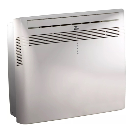
- Page 1 Assembly and operating instructions REMKO KWT 200 DC Local inverter room air conditioner without outdoor unit Read the instructions prior to performing any task! 0103-2015-03 Edition 1, en_GB...
- Page 2 Read these operating instructions carefully before commis- sioning / using this device! These instructions are an integral part of the system and must always be kept near or on the device. Subject to modifications; No liability accepted for errors or mis- prints! Installation and operating instructions (translation of the orig- inal)
-
Page 3: Table Of Contents
Table of contents Safety and usage instructions......................4 1.1 General safety notes........................4 1.2 Identification of notes........................4 1.3 Personnel qualifications........................4 1.4 Dangers of failure to observe the safety notes................4 1.5 Safety-conscious working....................... 4 1.6 Safety notes for the operator......................5 1.7 Safety notes for installation, maintenance and inspection.............. -
Page 4: Safety And Usage Instructions
REMKO KWT Safety and usage instructions CAUTION! This combination of symbol and signal word 1.1 General safety notes warns of a potentially hazardous situation, which if not avoided may cause injury or mate- Carefully read the operating manual before com- rial and environmental damage. -
Page 5: Safety Notes For The Operator
"certificate of warranty" to conditions stipulated in this manual and comply REMKO GmbH & Co. KG at the time when the with all applicable regional regulations. units are purchased and commissioned. -
Page 6: Transport And Packaging
REMKO KWT 1.11 Transport and packaging The devices are supplied in a sturdy shipping con- tainer. Please check the equipment immediately upon delivery and note any damage or missing parts on the delivery and inform the shipper and your contractual partner. For later complaints can not be guaranteed. -
Page 7: Technical Data
Technical data 2.1 Unit data Series KWT 200 DC Local, two-hose air conditioner with Operating mode inverter technology for cooling and heating 1.85 (1.10-2.93) Nominal cooling output Energy efficiency ratio - cooling 2.61 Energy efficiency rating EER kWh/60 Energy consumption, hourly 0.71... -
Page 8: Unit Dimensions
Contains greenhouse gas acc. to Kyoto protocol (GWP 1975) 2.2 Unit dimensions Fig. 1: Unit dimensions KWT 200 DC (All measurements in mm) We reserve the right to modify the dimens. and design as part of the ongoing techn. development process. -
Page 9: Design And Function
Design and function to reach the setpoint as soon as possible. In each of the above mentioned operating modes, the com- 3.1 Unit description pressor adjusts its power exactly to the require- ments and thereby regulates the setpoint tempera- The local room air conditioner consists of a com- ture with minimal temperature fluctuations. -
Page 10: Operation
REMKO KWT Operation When changing the battery, make sure that only 2 x 1.5 V AAA alkaline batteries are used. These can Infrared remote control be found on the rear of the infrared remote control and can be accessed via the sliding cover. Make a... - Page 11 Remote control keys and their functions A symbol is shown on the display for a short time to indicate that the settings are being transferred. " " and " " keys Temperature setting Using these keys, the set temperature can be increased or lowered in 1 °C steps "...
- Page 12 REMKO KWT Programming the timer: Auxiliary heater [C]: Switch-on time The unit works in recirculation mode and is sup- ported by the auxiliary heater Pressing the "ST" key once, causes the time to flash and "ON" to appear in the display. Using the "H"...
- Page 13 Remote control display Fig. 7: Remote control display Selected mode 3b: High 1a: Heating mode 3c: Medium 1b: Dehumidification mode 3d: Low 1c: Night mode "iFEEL" function activated 1d: Cooling mode Signal transfer to unit 1e: Automatic mode Current value / setpoint 1f: Turbo mode 6a: Current room temperature Selected flap setting/ Swing function...
-
Page 14: Assembly And Installation
REMKO KWT Assembly and installation Important notes prior to installation When installing the unit, observe the following points: The installation must be carried out on a flat wall Ensure that the wall meets the static requirements (consider the weight of the device as well as the required holes to be drilled) Install the device at least 10 cm from the floor. - Page 15 Installation Now insert the supplied internal spigots as well as the outer covers (the air flow louvres Perform the installation as follows: should point towards the ground). Fasten these with the screws supplied. Cut the required holes out of the mounting template.
- Page 16 REMKO KWT < 10 cm Max. 2 m Install the mounting plate on the wall as shown on the mounting template [1]. The number of screws required depends on the wall's properties. Do not leave a gap between the mounting plate and the wall.
- Page 17 Important! Check that the condensate hose is cor- rectly laid. In cooling mode, the conden- sate which is produced is evaporated in the unit and fed to the outside through the exhaust air duct. This is, however, only possible when the usable limits are observed.
- Page 18 REMKO KWT Mounting template Fig. 11: Mounting template (supplied with delivery) A: Total width 3: Hole for air intake B: Minimum distance to the floor 4: Hole for air outlet 1: Mounting rail 5: Hole for condensate drainage (only required in...
-
Page 19: Electrical Wiring
Electrical wiring Electrical drawings 373170120 ELi713 000585 4 11 Fig. 12: Electrical drawings Heat gas probe 11: Heat exchanger input probe Assembly display 12: Float switch Flaps motor 13: Remote control cable Connection to contact J5B and J1 14: Heat exchange output probe 4-way valve 15: Electronic expansion valve Connection to contact J1 and J8... -
Page 20: Commissioning
REMKO KWT Commissioning Automatic operating mode Use the " " key to switch the unit on. Before every commissioning the air inlet and outlet openings should be checked for foreign bodies and Using the " " key or the " " key, select the the air inlet filter must be checked for dirt. - Page 21 Recirculation mode Use the " " key to switch the unit on. Use the " " key to select recirculation mode (a fan symbol appears in the display). Select the desired fan speed using the " " key. *) When pressing the " "...
-
Page 22: Troubleshooting And Customer Service
REMKO KWT Troubleshooting and customer service The unit has been manufactured using state-of-the-art production methods and has been tested several times to ensure that it works properly. If malfunctions should occur, please check the unit as detailed in the list below. Please inform your dealer if the unit is still not working correctly after all the function checks have been performed. - Page 23 Fault analysis LED indicator Possible causes Standby Operating lamp Timer (yellow) (green) (blue) Flashes Condensate liquid level switch has triggered Flashes slowly Turbo mode active Flashes Flashes Air inlet sensor fault Flashes Flashes Outside temperature sensor fault Flashes Flashes Evaporator sensor fault Flashes Flashes Condenser sensor fault...
-
Page 24: Care And Maintenance
REMKO KWT Care and maintenance Switch the unit off and pull out the power plug. Regular care and observation of some basic points The filter is behind the front air intake grille. will ensure trouble-free operation and a long This grille can be folded out forward. Then service life. -
Page 25: Shutdown
Permanent shutdown The entire system should only be dismantled by a specialist firm familiar with all environmental aspects involved. REMKO GmbH & Co. KG or your sales partner will be pleased to provide details of refrigerant specialists in your area. -
Page 26: Exploded View Of The Unit And Spare Parts List
Exploded view of the unit and spare parts list 11.1 Exploded view of the unit Fig. 17: Exploded view of the unit - housing KWT 200 DC We reserve the right to modify the dimensions and design as part of the ongoing technical development process. - Page 27 Fig. 18: Exploded view of the unit - cooling circuit KWT 200 DC We reserve the right to modify the dimensions and design as part of the ongoing technical development process.
- Page 28 REMKO KWT Fig. 19: Exploded view of the unit - cooling circuit KWT 200 DC We reserve the right to modify the dimensions and design as part of the ongoing technical development process.
-
Page 29: Spare Parts List
Spare parts list Please contact REMKO GmbH & Co. KG directly to order spare parts. All the spare part numbers for your unit can be found in the download area at www.remko.de. IMPORTANT! To ensure the correct delivery of spare parts, please always the device type with the corresponding serial number (see type plate) No. - Page 30 REMKO KWT No. Designation KWT 200 DC Condenser Condensate pump Compressor connection cable Condensate check valve Compressor Compressor insulation Condensate hose, small Condensate hose, large Floor housing Housing body Suspended unit Cross piece Fan cover Fan roller mounting plate Fan bearing...
-
Page 31: Index
Index Assembly ......14 Maintenance ......24 Mounting template . - Page 32 REMKO KWT...
- Page 34 REMKO KWT...
- Page 36 SFlb Customer Service Our equipment operates precisely and reliably. However, in the event of a fault, REMKO customer service is quickly at the scene. Our comprehensive network of experienced dealers always guarantees quick and REMKO GmbH & Co. KG reliable service.
Need help?
Do you have a question about the KWT 200 DC and is the answer not in the manual?
Questions and answers