Table of Contents
Advertisement
Quick Links
Advertisement
Table of Contents

Subscribe to Our Youtube Channel
Related Manuals for REMKO KWD EC Series


Summary of Contents for REMKO KWD EC Series
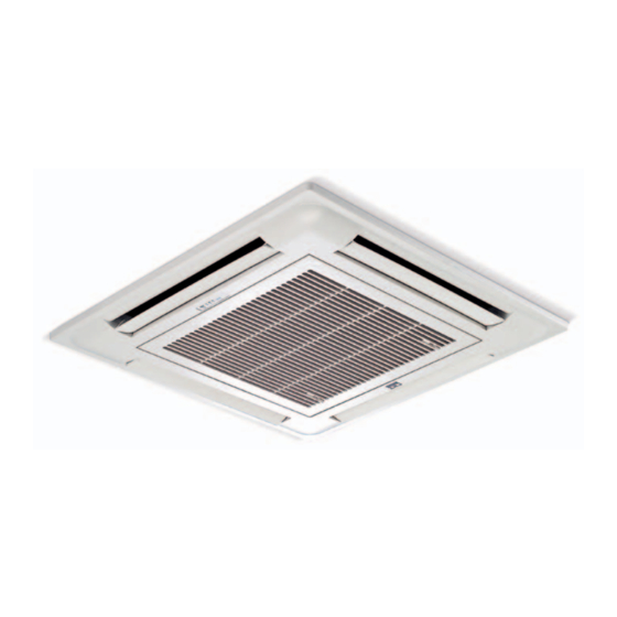
- Page 1 Assembly and operating instructions REMKO KWD EC series Chilled water ceiling cassettes with EC fans dual conductor version KWD 25 EC, KWD 35 EC, KWD 45 EC, KWD 55 EC, KWD 70 EC, KWD 85 EC, KWD 100 EC Edition GB -11...
-
Page 3: Table Of Contents
Contents Safety notes Environmental protection and recycling Transport and packaging Guarantee Unit description System layout Operation 7-16 Shutdown Care and maintenance 17-18 Troubleshooting and customer service 19-20 Installation instructions for qualified personnel Installation 22-25 Condensate drainage connection Electrical wiring Electrical drawings Configuration, external controllers, enabling contact 28-29 Speed control with external signal control... -
Page 4: Safety Notes
REMKO KWD EC series Environmental Safety notes protection Carefully read the operating The operational safety ■ and recycling manual before placing the unit of the units and components in service for the first time. is only assured if they are... -
Page 5: Guarantee
"certificate of warranty" Group control using the wired ■ to REMKO GmbH & Co. KG Thanks to the new and very robust room temperature controller at the time when the units are brushless EC fans (electronically and switching relay (provided purchased and commissioned. -
Page 6: System Layout
REMKO KWD EC series System layout Intended use The unit is designed operating medium is then fed Depending on the model for a 2-conductor system. in once again to the unit medium and the equipment, the units are The system has 2 medium pipes circuit. -
Page 7: Operation
0 - 5/10V signal Control in REMKO networks with five-stage fan control Control in REMKO networks with five-stage fan control and group operation on all slave units and single control on specific slave units... -
Page 8: Operation
REMKO KWD EC series Operation with IR remote Manual mode control that is fitted The unit can also be started as standard manually. Press the RESET key on the receiver The unit is easily operated using unit of the cover to activate the standard infrared remote automatic mode. - Page 9 Keys on the remote control Keys on the remote control "FAN" key "POWER" key Press this key to set the Press this key to start the unit. desired fan speed. 4 stages are available here: Automatic, high, medium and low fan stage. "TEMP"...
- Page 10 REMKO KWD EC series Key functions A symbol is shown on the display to indicate that the settings are being transferred. POWER Key Press the POWER key to activate/deactivate the indoor unit. The pro- grammed settings and parameters are shown on the display before the unit switches off.
- Page 11 MODE Key Press the MODE key to change to another mode. A total of 5 modes are available: 1. COOL/HEAT Automatic mode, automatic selection of cooling or heating mode 2. COOL Cooling mode, mainly used in summer 3. DRY Dehumidification mode, summer or winter mode 4.
- Page 12 REMKO KWD EC series Fan MODE Press the MODE key once or repeatedly to switch This mode allows the heat to recirculation mode. trapped under the ceiling to be In this mode, the unit is used circulated to the lower regions as an air circulation unit.
- Page 13 After pressing the "FAN" key, "AUTO" is shown on the fan speed dis- FAN Key play. Each press of the key cycles through a high (H), medium (M) and low (L) speed setting. In AUTO mode, the controller selects the fan speed automatically. The greater the difference between the target and actual temperature, the higher the speed.
- Page 14 REMKO KWD EC series The TIME-ON/-OFF keys are used to program the switch-on/off time, TIME Keys the TIME-SET key to set the time. Switch-on time Press the TIME-ON or TIME-OFF key to activate the timer. The clock display then disappears. The timer symbol for the switch-on/off time will flash.
- Page 15 NETWORK Key The NETWORK key enables the settings on the master unit (leading unit) to be transferred to all salve units (subsequent units) on the network. All units confirm that they have received the settings correctly by beeping. The infrared remote controls do not copy the changed settings. Press and hold the key for 5 seconds to transfer.
- Page 16 REMKO KWD EC series The following table is used to assign the relevant selected addresses to the corresponding room designation. The procedure for assigning addresses to units is described in the "Configuration" chapter. The master unit must be allocated address 00. Also note that the same address can also be assigned to multiple units in order to operate a corresponding unit group.
-
Page 17: Shutdown
We recommend that you take ■ out a maintenance contract REMKO GmbH & Co. KG or your with an annual service contractual partner will be pleased from an appropriate specialist to provide a list of certified firms firm. - Page 18 REMKO KWD EC series Cleaning the filter Cleaning the condensate pump 1. Disconnect the power supply The unit includes a built- to the unit. in condensate pump for pumping the condensate to a drain 2. Open and fold down the air at a higher level.
-
Page 19: Troubleshooting And Customer Service
Troubleshooting and customer service The unit and components are manufactured using state-of-the-art production methods and tested several times to verify that they function correctly. However, if malfunctions should occur, please check the functions as detailed in the list below. With systems for cooling or heating with indoor units, chillers or heating systems the chapter "Troubleshooting and customer service"... - Page 20 REMKO KWD EC series Malfunction Possible cause Check Remedial measures Is electrical power present Valve assembly jammed, not at the valve head or has Have the valve head replaced working, not yet fully activated. the time period of 3 minutes or wait for time period to pass.
-
Page 21: Installation Instructions For Qualified Personnel
Installation instructions for qualified personnel Important notes prior Selecting the installation location Avoid unnecessary bends. ■ to installation This minimises the pressure loss The unit is specifically designed in the lines. Observe the operating manuals ■ for horizontal mounting Make all electrical connections for the indoor unit and the ■... -
Page 22: Installation
REMKO KWD EC series Installation Unit installation CAUTION Unit mount Installation should only be KWD 25 EC-55 EC The unit is mounted with the cover performed by authorised face down on four threaded rods. specialists. Take into account the ceiling grid and any other installations. - Page 23 Required system components CAUTION increases and the unit's cooling Valve assembly (accessory) or heating capacity reduces. Glycol tolerant air vent valves are necessary when using In 2-conductor systems, cold All system components must be media that contain glycol. or warm medium is fed through approved for use with glycol.
- Page 24 REMKO KWD EC series Connections to adjoining room The maximum pipe length Installation instructions ■ and fresh air intake of 7 m must not be exceeded Proceed as follows to make KWD 70 EC-100 EC (page 22, Fig. 12). the connections to a second room...
-
Page 25: Condensate Drainage Connection
Adjoining room connection Fresh air connection max. Outdoor air inlet Main room Adjoining room Inside Outside Condensate drainage connection If the temperature falls below If the level of the condensate After installation is complete, ■ ■ the dew point, condensate will drainage line on the unit is check for unobstructed form on the cooling fins during... -
Page 26: Electrical Wiring
REMKO KWD EC series Electrical wiring CAUTION CAUTION Control box cover KWD 25 EC to 100 EC All electrical installation work Check all plug and terminal is to be performed by specialist connections to verify companies. Disconnect the that they are tight and make power supply when connecting a permanent contact. -
Page 27: Electrical Drawings
Electrical drawings KWD 25 EC to 100 EC Power supply 230V, 50Hz IR receiver cover JP 1: Jumper plugged in/closed for the last unit on an internal network Probe, ambient air JP 2: Select the fan motor control voltage open = 0 - 5VDC Anti-freeze protection plugged in = 0 - 10VDC probe... -
Page 28: Configuration, External Controllers, Enabling Contact
REMKO KWD EC series Configuration Configuration is carried out using Network configuration (DIP2) The units can also be adjusted The addresses for the leading white slide switch SW1-4 for DIP1, to requirements retroactively (master) and subsequent (slave) SW1-6 for DIP2 and SW 1-8... -
Page 29: Speed Control With External Signal Control
Using extneral controllers External controller Strapping plug Circuit diagram The units can be controlled 24VAC 230VAC using the controller provided by the factory or using an external controller. The external controller can be used to activate the three Fan stages, "High", "Medium"... -
Page 30: Internal Network
REMKO KWD EC series Using the internal network Up to 32 units can be operated Network with infrared remote Network with cabled remote at the same time thanks to the controls controls parallel connection via a bus line (accessory). The units can access... -
Page 31: Leak Testing
Leak testing Before commissioning Commissioning Anti-freeze protection Once the connection has been Commissioning should only be ■ for the medium established successfully, the leak performed and documented test is carried out. If a water-glycol mixture is used, by specially trained personnel. 1. -
Page 32: Unit Dimensions
REMKO KWD EC series Function test of heating operating 4. Use the remote control 6. Check the unit control system to switch on the unit and select using the functions described mode the heating mode, maximum in the "Operation" chapter. - Page 33 Services Cooling capacity Medium inlet 5 °C 7 °C 9 °C 11 °C 13 °C Medium nominal Cooling capacity Flow Pressure volume loss [kW] [kW] [kW] [kW] [kW] [kW] [kW] [kW] [kW] [kW] [kPa] 180 20.8 0.21 1.38 0.89 1.10 0.81 0.94 0.62...
- Page 34 REMKO KWD EC series Heating capacity Medium inlet Medium nominal 35 °C 40 °C 45 °C 50 °C 55 °C 60 °C 65 °C Heating capacity Medium Pressure flow rate loss [kW] [kW] [kW] [kW] [kW] [kW] [kW] [kPa] 180 20.8 0.21...
-
Page 35: Technical Data
Technical data Series KWD 25 EC KWD 35 EC KWD 45 EC KWD 55 EC Chilled water ceiling cassette with EC fans, single Euroraster format, Operating mode 2-conductor version Nominal cooling output 2.55 3.16 4.38 5.20 Nominal cooling output, sensitive 1.81 2.24 3.10... - Page 36 REMKO KWD EC series Technical data Series KWD 70 EC KWD 85 EC KWD 100 EC Chilled water ceiling cassette with EC fans, dual Euroraster format, Operating mode 2-conductor version Nominal cooling output 6.93 8.41 9.68 Nominal cooling output, sensitive 4.89...
-
Page 37: Exploded View Of The Unit
KWD 25 EC to 55 EC unit illustration We reserve the right to modify the dimensions and design as part of the ongoing technical development process. KWD 25 EC to 55 EC spare parts list Designation KWD 25 EC KWD 35 EC KWD 45 EC KWD 55 EC Air inlet grill... - Page 38 REMKO KWD EC series KWD 70 EC to 100 EC unit illustration We reserve the right to modify the dimensions and design as part of the ongoing technical development process. KWD 70 EC to 100 EC spare parts list Designation...
- Page 40 This has given us the reputation of being more than just an excellent, reliable supplier: REMKO, a partner who helps to solve problems. Sales REMKO offers not just a well-established sales network both nationally...
Need help?
Do you have a question about the KWD EC Series and is the answer not in the manual?
Questions and answers