Sign In
Upload
Download
Table of Contents
Contents
Add to my manuals
Delete from my manuals
Share
URL of this page:
HTML Link:
Bookmark this page
Add
Manual will be automatically added to "My Manuals"
Print this page
×
Bookmark added
×
Added to my manuals
Manuals
Brands
FLENDER Manuals
Industrial Equipment
REDUREX
Operating instructions manual
FLENDER REDUREX Operating Instructions Manual
Gear units 5200en
Hide thumbs
1
2
3
4
Table Of Contents
5
6
7
8
9
10
11
12
13
14
15
16
17
18
19
20
21
22
23
24
25
26
27
28
29
30
31
32
33
34
35
36
37
38
39
40
41
42
43
44
45
46
47
48
49
50
51
52
53
54
55
56
57
58
59
60
61
62
63
64
65
66
67
68
69
70
71
72
73
74
75
76
77
78
79
80
81
82
83
84
85
86
87
88
89
90
91
92
93
94
95
96
97
98
99
100
101
102
103
104
105
106
107
108
109
110
111
112
113
114
115
116
117
118
119
120
121
122
123
124
125
126
127
128
page
of
128
Go
/
128
Contents
Table of Contents
Bookmarks
Table of Contents
Edition
Table of Contents
General Information
Introduction
Lubricants
General Warnings and Symbols
Figure 3-1 Output Shaft Versions
Figure 3-2 Sign: Lubrication Point
Figure 3-3 Gear Unit Equipment for Type S.N Gear Units
Figure 3-4 Gear Unit Equipment for Type K.N Gear Units
Figure 3-5 Rotary Shaft Sealing Ring
Figure 3-6 Fey Labyrinth Seal
Figure 3-7 Labyrinth Seals
Taconite Seal
Figure 3-8 Taconite-Seal
Tacolab Seal
Cooling
Fan
Figure 3-9 Tacolab Seal
Cooling Coil
Mounted Oil Supply System
Mounted Oil Supply System with Air-Oil Cooler
Mounted Oil Supply System with Water-Oil Cooler
Oil Filter
Pump
Separate Oil Supply System
Backstop
Couplings
Heating
Shrink Disks
Table 3-1 Information about the Specific Heat Output
Oil Level Indicator
Oil Level Monitoring System
Bearing Monitoring
Bearing Monitoring Using a Pt 100 Resistance Thermometer
Oil Temperature Monitoring System
Bearing Monitoring by Acceleration Sensor
Auxiliary Drive
Overrunning Clutch
Application Planning
Scope of Delivery
Transport
Attachment Points
Safety Instructions
Security Notes
The Five Safety Rules
General Information
Table 2-1 Symbols and Markings
Table 2-2 General Warnings
Special Types of Danger and Personal Protective Equipment
Intended Use
Description
General Description
Output Version
Housing
Gear Unit Oil Supply
Pressure Lubrication
Splash Lubrication
Bearing Arrangement of the Shafts
Labyrinth Seals
Rotary Shaft Sealing Rings
Shaft Seal
Figure 4-3 Position of the Attachment Points, at Type S.N ≤ 280 and K.N ≤ 280 Gear Units
Oil Filling and Oil Drain
Special Features Relating to Gear Unit Lubrication
General Assembly Instructions
Mounting
Unpacking the Gear Unit
Foundation
Gear Unit Mounting
Fastening
Mounting on a Housing Foot
Mounting the Gear Unit Swing Base
Mounting the Torque Arm for the Gear Unit Housing
Shaft-Mounted Gear Unit with Hollow Shaft and Parallel Keyway
Mounting
Axial Locking
Dismantling
Gear Unit Fastening
Shaft-Mounted Gear Unit with Hollow Shaft and Shrink Disk
Mounting
Pulling on with Integrated du Bushing
Axial Locking
Dismantling the Shaft-Mounted Gear Unit
Couplings
Connecting Components
Connecting the Cooling Coil
Gear Units with Mounted Components
Connecting the Air-Oil Cooler
Connecting the Water-Oil Cooler
Electrical Connections
Installing a Separate Oil Supply System
Connecting the Oil Temperature Monitor
Connecting the Oil-Level Monitoring System
Connecting the Bearing Monitoring System
Connecting the Heating Element
Introduction
Tightening Procedure
Bolt Connection Classes
Table 5-1 Information on Tightening Fastening Bolts
Table 5-2 Preload Forces and Tightening Torques
Table 7-1 Operating Data
Taking the Unit out of Service
General Maintenance Activities
Maintenance
Maintenance Schedule
Table 8-1 Maintenance and Servicing Activities
Cleaning the Fan and Gear Unit
Maintenance and Service Work
Checking the Oil Temperature
Cleaning the Venting Screw
Filling the Backstop with Oil
Replacing the Backstop
Measuring the Temperature at the Rolling-Contact Bearings
Measuring the Vibration Levels of the Rolling-Contact Bearings
Checking the Auxiliary Drive
Checking the Cooling Coil
Filling the Overrunning Clutch of the Auxiliary Drive with Oil
Check that All of the Fastening Bolts Are Tight
Inspecting the Shrink Disk
Final Work
General Inspection of the Gear Unit
Possible Faults
Table 8-2 Possible Faults and Their Rectification
Service & Support
Disposal
Spare Parts
Declaration of Incorporation
Quality Documents
General Technical Data
Technical Data
Ambient Temperature
Types
Final Work
Commissioning
Gear Units with Cooling Coil
Measures to be Taken Prior to Commissioning
Gear Unit with Auxiliary Drive
Gear Unit with Backstop
Gear Units with Oil Supply System
Oil Level Monitoring System
Measures to be Taken During Commissioning
Oil Temperature Monitoring System
Heating
Irregularities in Operation
Operating Data
Operation
Tightening Torques and Preload Forces
B.2 Ambient Temperature
B.4 Weights
Table B-1 Weights
Weights
Table B-2 Weights
Table B-3 Weights
Enveloping Surface Sound Pressure Level
Index
Advertisement
Quick Links
1
General Information
2
Figure 3-1 Output Shaft Versions
3
Figure 3-3 Gear Unit Equipment for Type S.n Gear Units
Download this manual
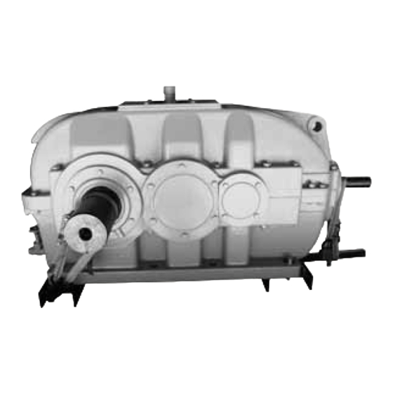
FLENDER GEAR UNITS
REDUREX Gear unit
Operating Instructions 5200en
Edition 03/2019
S.N, S.O, S.A, K.N, K.O, K.A, S.NS, S.LS, S.AS, S.OS, S.DS, K.NS, K.LS, K.AS, K.OS, K.DS, K.OV, K.OH,
K.AU, SOND
80...800
Table of
Contents
Previous
Page
Next
Page
1
2
3
4
5
Advertisement
Table of Contents
Need help?
Do you have a question about the REDUREX and is the answer not in the manual?
Ask a question
Questions and answers
Related Manuals for FLENDER REDUREX
Industrial Equipment FLENDER H Series Assembly And Instructions
Gear unit (110 pages)
Industrial Equipment FLENDER RUPEX RWN Assembly And Operating Instructions Manual
(80 pages)
Industrial Equipment FLENDER RUPEX RWS Assembly And Operating Instructions Manual
(80 pages)
Industrial Equipment FLENDER RUPER RWB Assembly And Operating Instructions Manual
(78 pages)
Industrial Equipment FLENDER BNN Operating Instructions Manual
Flender couplings (66 pages)
Industrial Equipment FLENDER BIPEX-S Operating Instructions Manual
Flender couplings (66 pages)
Industrial Equipment FLENDER BKK Operating Instructions Manual
Flender couplings (66 pages)
Industrial Equipment FLENDER S.A Series Operating Instructions Manual
Gear units 5200en (128 pages)
Industrial Equipment FLENDER H Series Operating Instructions Manual
Gear unit (110 pages)
Industrial Equipment FLENDER ARPEX ARS-6 Operating Instructions Manual
Couplings (36 pages)
Industrial Equipment FLENDER ZAPEX Operating Instructions Manual
Couplings (16 pages)
Industrial Equipment FLENDER ZAPEX-ZI Manual
Gear couplings acc. to international standards, grease lubrication, o-ring seal (28 pages)
Industrial Equipment FLENDER ELPEX-B EBWT Series Manual
Highly flexible couplings (16 pages)
Industrial Equipment FLENDER N-EUPEX Manual
Flexible couplings (40 pages)
Industrial Equipment FLENDER ELPEX-B EBWT 105 Manual
Highly flexible couplings (20 pages)
Industrial Equipment FLENDER COUPLINGS N-EUPEX 3103en Assembly And Operating Instructions Manual
(64 pages)
This manual is also suitable for:
S.a series
S.n series
S.o series
K.o series
K.n series
K.a series
...
Show all
S.ns series
S.as series
S.ls series
S.os series
S.ds series
K.ns series
K.ls series
K.os series
K.as series
K.ds series
K.oh series
K.ov series
K.au series
Sond series
Table of Contents
Save PDF
Print
Rename the bookmark
Delete bookmark?
Delete from my manuals?
Login
Sign In
OR
Sign in with Facebook
Sign in with Google
Upload manual
Upload from disk
Upload from URL


Need help?
Do you have a question about the REDUREX and is the answer not in the manual?
Questions and answers