Table of Contents
Advertisement
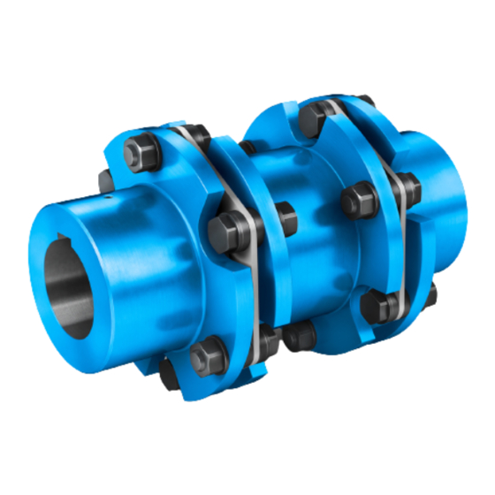
FLENDER COUPLINGS
- - - - - - - - - - - - - - - - - - - - - - - - - - - - - - - - - - - - - - - - - - - - - - - - - - - - - - - - - - - - - -
ARPEX
- - - - - - - - - - - - - - - - - - - - - - - - - - - - - - - - - - - - - - - - - - - - - - - - - - - - - - - - - - - - - -
Operating instructions 8704 en
Edition 01/2019
- - - - - - - - - - - - - - - - - - - - - - - - - - - - - - - - - - - - - - - - - - - - - - - - - - - - - - - - - - - - - -
ARS-6, ARP-6, ARH-8, ARC-6/8/10, ARW-4/6, ARF-6
- - - - - - - - - - - - - - - - - - - - - - - - - - - - - - - - - - - - - - - - - - - - - - - - - - - - - - - - - - - - - -
flender.com
Advertisement
Table of Contents


Need help?
Do you have a question about the ARPEX ARS-6 and is the answer not in the manual?
Questions and answers