Sign In
Upload
Download
Table of Contents
Contents
Add to my manuals
Delete from my manuals
Share
URL of this page:
HTML Link:
Bookmark this page
Add
Manual will be automatically added to "My Manuals"
Print this page
×
Bookmark added
×
Added to my manuals
Manuals
Brands
FLENDER Manuals
Industrial Equipment
BNN
Operating instructions manual
FLENDER BNN Operating Instructions Manual
Flender couplings
Hide thumbs
1
2
3
4
Table Of Contents
5
6
7
8
9
10
11
12
13
14
15
16
17
18
19
20
21
22
23
24
25
26
27
28
29
30
31
32
33
34
35
36
37
38
39
40
41
42
43
44
45
46
47
48
49
50
51
52
53
54
55
56
57
58
59
60
61
62
63
64
65
66
page
of
66
Go
/
66
Contents
Table of Contents
Bookmarks
Table of Contents
Safety Instructions
Table of Contents
1 Introduction
About These Instructions
Text Attributes
Copyright
Service and Support
2 Safety Instructions
General Information
Intended Use
General Warning Notices
Spare Parts
3 Description
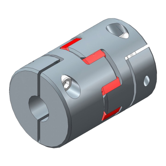
Figure 3-1 Type BNN
Figure 3-2 Type BGG
Figure 3-3 Type BCC
Figure 3-4 Type BHH
Figure 3-5 Type BKK
Figure 3-6 Type BCS
Figure 3-7 Type BHH-W
4 Application Planning
Transport of the Coupling
Storage of the Coupling
Figure 4-1 Transport Symbols
Table 4-1 Types of Preservative Agents for Long-Term Storage
5 Assembly
Preparatory Work
Assembling the Coupling
Assembling the Coupling Parts
Attach the Coupling Part N (1) with Parallel Key to the Shaft
Attaching Coupling Part G (2), C (3), H (4) or K (5) to the Shaft with a Clamping Connection
Attach Coupling Part S (6) to the Hollow Shaft with a Clamping Connection
Plug-In Assembly of the Coupling Halves
Plug-In Assembly of Types BNN, BGG, BCC, BHH, BKK and BCS
Plug-In Assembly of Type BHH-W
Aligning the Coupling
Purpose of Alignment
Possible Misalignment
Figure 5-1 Possible Misalignment
Axial Misalignment
Angular Misalignment
Radial Misalignment
6 Commissioning
7 Operation
Normal Operation of the Coupling
Faults - Causes and Rectification
Procedure in the Event of Malfunctions
Identifying the Fault Cause
Possible Faults
Possible Causes
Correcting Faults
Replacing Wearing Parts
Correcting the Changed Alignment
8 Servicing
Maintenance Intervals
Maximum Permissible Torsional Backlash
Replacing Wearing Parts
Figure 8-1 Markings for Calculating the Torsional Backlash
Removing Coupling Part N (1)
Removing Coupling Part G (2), C (3), H (4) or K (5)
Removing Coupling Part S (6)
9 Service and Support
Contact
10 Disposal
11 Spare Parts
Ordering Spare Parts
Spare Parts Drawing and Spare Parts List
Type BNN
Figure 11-1 Spare Parts Drawing for Type BNN
Type BGG
Figure 11-2 Spare Parts Drawing for Type BGG
Type BCC
Figure 11-3 Spare Parts Drawing for Type BCC
Type BHH
Figure 11-4 Spare Parts Drawing for Type BHH
Type BKK
Figure 11-5 Spare Parts Drawing for Type BKK
Type BCS
Type BHH-W
Technical Data
Speeds, Geometry Data and Weights
Type BNN
Type BGG
A.1.2 Type BGG
Type BCC
A.1.3 Type BCC
Type BHH
A.1.4 Type BHH
Type BKK
A.1.5 Type BKK
Type BCS
A.1.6 Type BCS
Type BHH-W
A.1.7 Type BHH-W
Shaft Misalignment Values During Operation
Tightening Torques and Widths A/F
Tightening Procedure
Cam Rings
Use and Storage of the Cam Rings
BIPEX-S Cam Ring (20)
A.5 Cam Rings
Advertisement
Quick Links
Download this manual
FLENDER COUPLINGS
BIPEX-S
Operating Instructions 3410en
Edition 10/2017
BNN, BGG, BCC, BHH, BKK, BCS, BHH-W
Table of
Contents
Previous
Page
Next
Page
1
2
3
4
5
Advertisement
Table of Contents
Need help?
Do you have a question about the BNN and is the answer not in the manual?
Ask a question
Questions and answers
Related Manuals for FLENDER BNN
Industrial Equipment FLENDER BIPEX-S BNN Assembly And Operating Instructions Manual
(68 pages)
Industrial Equipment FLENDER H Series Operating Instructions Manual
Gear unit (110 pages)
Industrial Equipment FLENDER H RV Series Assembly And Operating Instructions Manual
Agitator gear unit (174 pages)
Industrial Equipment FLENDER H Series Assembly And Instructions
Gear unit (110 pages)
Industrial Equipment FLENDER BIPEX-S Operating Instructions Manual
Flender couplings (66 pages)
Industrial Equipment FLENDER BKK Operating Instructions Manual
Flender couplings (66 pages)
Industrial Equipment FLENDER B H 23 28 Series Assembly And Operating Instructions Manual
Belt-conveyor gear unit (154 pages)
Industrial Equipment FLENDER H SH Series Assembly Instructions Manual
Gear unit (172 pages)
Industrial Equipment FLENDER B3 A Series Assembly And Operating Instructions Manual
Belt-conveyor gear unit (132 pages)
Industrial Equipment FLENDER H V Series Assembly And Operating Instructions Manual
Gear units (164 pages)
Industrial Equipment FLENDER N-BIPEX BWN Assembly And Operating Instructions Manual
(68 pages)
Industrial Equipment FLENDER ARPEX ARS-6 Operating Instructions Manual
Couplings (36 pages)
Industrial Equipment FLENDER ZAPEX Operating Instructions Manual
Couplings (16 pages)
Industrial Equipment FLENDER ZAPEX-ZI Manual
Gear couplings acc. to international standards, grease lubrication, o-ring seal (28 pages)
Industrial Equipment FLENDER N-EUPEX Manual
Flexible couplings (40 pages)
Industrial Equipment FLENDER ELPEX-S Assembly And Operating Instructions Manual
(80 pages)
This manual is also suitable for:
Bipex-s
Bgg
Bhh
Bcs
Bkk
Bcc
...
Show all
Bhh-w
Bipex-s bnn
Bipex-s bgg
Bipex-s bcc
Bipex-s bhh
Bipex-s bkk
Bipex-s bcs
Bipex-s bhh-w
Table of Contents
Print
Rename the bookmark
Delete bookmark?
Delete from my manuals?
Login
Sign In
OR
Sign in with Facebook
Sign in with Google
Upload manual
Upload from disk
Upload from URL


Need help?
Do you have a question about the BNN and is the answer not in the manual?
Questions and answers