Sign In
Upload
Manuals
Brands
FLENDER Manuals
Industrial Equipment
K.OH Series
FLENDER K.OH Series Manuals
Manuals and User Guides for FLENDER K.OH Series. We have
1
FLENDER K.OH Series manual available for free PDF download: Operating Instructions Manual
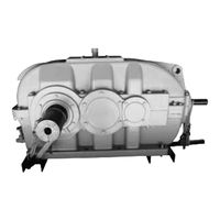
FLENDER K.OH Series Operating Instructions Manual (128 pages)
GEAR UNITS 5200en
Brand:
FLENDER
| Category:
Industrial Equipment
| Size: 1.24 MB
Table of Contents
Edition
4
Table of Contents
5
General Information
11
Introduction
11
Lubricants
12
General Warnings and Symbols
15
Figure 3-1 Output Shaft Versions
22
Figure 3-2 Sign: Lubrication Point
22
Figure 3-3 Gear Unit Equipment for Type S.N Gear Units
23
Figure 3-4 Gear Unit Equipment for Type K.N Gear Units
23
Figure 3-5 Rotary Shaft Sealing Ring
25
Figure 3-6 Fey Labyrinth Seal
26
Figure 3-7 Labyrinth Seals
26
Taconite Seal
26
Figure 3-8 Taconite-Seal
27
Tacolab Seal
27
Cooling
28
Fan
28
Figure 3-9 Tacolab Seal
28
Cooling Coil
29
Mounted Oil Supply System
30
Mounted Oil Supply System with Air-Oil Cooler
30
Mounted Oil Supply System with Water-Oil Cooler
32
Oil Filter
33
Pump
33
Separate Oil Supply System
33
Backstop
34
Couplings
35
Heating
36
Shrink Disks
36
Table 3-1 Information about the Specific Heat Output
37
Oil Level Indicator
38
Oil Level Monitoring System
38
Bearing Monitoring
39
Bearing Monitoring Using a Pt 100 Resistance Thermometer
39
Oil Temperature Monitoring System
39
Bearing Monitoring by Acceleration Sensor
40
Auxiliary Drive
41
Overrunning Clutch
42
Application Planning
45
Scope of Delivery
45
Transport
45
Attachment Points
47
Safety Instructions
13
Security Notes
13
The Five Safety Rules
13
General Information
14
Table 2-1 Symbols and Markings
14
Table 2-2 General Warnings
15
Special Types of Danger and Personal Protective Equipment
16
Intended Use
18
Description
21
General Description
21
Output Version
21
Housing
22
Gear Unit Oil Supply
24
Pressure Lubrication
24
Splash Lubrication
24
Bearing Arrangement of the Shafts
25
Labyrinth Seals
25
Rotary Shaft Sealing Rings
25
Shaft Seal
25
Figure 4-3 Position of the Attachment Points, at Type S.N ≤ 280 and K.N ≤ 280 Gear Units
48
Oil Filling and Oil Drain
50
Special Features Relating to Gear Unit Lubrication
50
General Assembly Instructions
51
Mounting
51
Unpacking the Gear Unit
52
Foundation
53
Gear Unit Mounting
53
Fastening
54
Mounting on a Housing Foot
54
Mounting the Gear Unit Swing Base
62
Mounting the Torque Arm for the Gear Unit Housing
62
Shaft-Mounted Gear Unit with Hollow Shaft and Parallel Keyway
63
Mounting
64
Axial Locking
66
Dismantling
66
Gear Unit Fastening
66
Shaft-Mounted Gear Unit with Hollow Shaft and Shrink Disk
67
Mounting
68
Pulling on with Integrated du Bushing
69
Axial Locking
70
Dismantling the Shaft-Mounted Gear Unit
70
Couplings
71
Connecting Components
73
Connecting the Cooling Coil
73
Gear Units with Mounted Components
73
Connecting the Air-Oil Cooler
74
Connecting the Water-Oil Cooler
74
Electrical Connections
75
Installing a Separate Oil Supply System
75
Connecting the Oil Temperature Monitor
76
Connecting the Oil-Level Monitoring System
76
Connecting the Bearing Monitoring System
77
Connecting the Heating Element
77
Introduction
77
Tightening Procedure
77
Bolt Connection Classes
78
Table 5-1 Information on Tightening Fastening Bolts
78
Table 5-2 Preload Forces and Tightening Torques
79
Table 7-1 Operating Data
89
Taking the Unit out of Service
90
General Maintenance Activities
91
Maintenance
91
Maintenance Schedule
92
Table 8-1 Maintenance and Servicing Activities
92
Cleaning the Fan and Gear Unit
93
Maintenance and Service Work
93
Checking the Oil Temperature
94
Cleaning the Venting Screw
94
Filling the Backstop with Oil
95
Replacing the Backstop
95
Measuring the Temperature at the Rolling-Contact Bearings
96
Measuring the Vibration Levels of the Rolling-Contact Bearings
96
Checking the Auxiliary Drive
97
Checking the Cooling Coil
97
Filling the Overrunning Clutch of the Auxiliary Drive with Oil
97
Check that All of the Fastening Bolts Are Tight
98
Inspecting the Shrink Disk
98
Final Work
99
General Inspection of the Gear Unit
99
Possible Faults
99
Table 8-2 Possible Faults and Their Rectification
100
Service & Support
105
Disposal
107
Spare Parts
109
Declaration of Incorporation
111
Quality Documents
111
General Technical Data
113
Technical Data
113
Ambient Temperature
116
Types
116
Final Work
80
Commissioning
83
Gear Units with Cooling Coil
83
Measures to be Taken Prior to Commissioning
83
Gear Unit with Auxiliary Drive
84
Gear Unit with Backstop
84
Gear Units with Oil Supply System
85
Oil Level Monitoring System
85
Measures to be Taken During Commissioning
86
Oil Temperature Monitoring System
86
Heating
87
Irregularities in Operation
89
Operating Data
89
Operation
89
Tightening Torques and Preload Forces
79
B.2 Ambient Temperature
116
B.4 Weights
118
Table B-1 Weights
118
Weights
118
Table B-2 Weights
119
Table B-3 Weights
120
Enveloping Surface Sound Pressure Level
121
Index
123
Advertisement
Advertisement
Related Products
FLENDER K.O Series
FLENDER K.OS Series
FLENDER K.OV Series
FLENDER K.N Series
FLENDER K.A Series
FLENDER K.NS Series
FLENDER K.AS Series
FLENDER K.AU Series
FLENDER K.SH
FLENDER K.HH
FLENDER Categories
Industrial Equipment
Accessories
Sander
Adapter
Tools
More FLENDER Manuals
Login
Sign In
OR
Sign in with Facebook
Sign in with Google
Upload manual
Upload from disk
Upload from URL